end upgrade for the Advanced Photon Source (APS) storage ring. This system is ... This will enable us to utilize the top end of the receiver's dynamic range. The.
Advanced Photon Source Monopulse rf Beam Position Monitor Front-End Upgrade* Robert M. Lill and Glenn A. Decker Advanced Photon Source, Argonne National Laboratory 9700 South Cass Avenue, Argonne, Illinois 60439 USA
Abstract. This paper will describe and analyze the rf beam position monitor (RFBPM) frontend upgrade for the Advanced Photon Source (APS) storage ring. This system is based on amplitude-to-phase (AM/PM) conversion monopulse receivers. The design and performance of the existing BPM front-end will be considered as the base-line design for the continuous effort to improve and upgrade the APS beam diagnostics. The upgrade involves redesigning the in-tunnel filter comparator units to improve insertion loss, return loss, and band-pass filter-matching that presently limit the different fill patterns used at APS.
INTRODUCTION The Advanced Photon Source (APS) is a third-generation synchrotron x-ray source that provides intense x-rays for basic and applied research. The stability of the x-ray beam is imperative for the operation of the APS. The storage ring beam stability must be less than 17 microns rms horizontally and 4.5 microns rms vertically in the frequency range from DC to 30 Hz. This beam stability is largely dependent on the quality and accuracy of the BPM system. The rf beam position monitor (RFBPM) system provides single turn capabilities for commissioning and diagnosing machine problems. The RFBPMs also provide the input to the beam feedback systems and the beam position limit detector (BPLD). The specification of the APS storage ring RFBPM system is listed in Table 1. The RFBPM upgrade will provide improved signal strength to the input of the receiver. This will enable us to utilize the top end of the receiver’s dynamic range. The upgrade will also reduce VSWR problems and band-pass filter side lobes that will allow the accelerator to be operated with less dead time between bunch trains. The upgrade will also address the calibration and maintainability of the system. * Work supported by U.S. Department of Energy, Office of Basic Energy Sciences under Contract No. W-31-109-ENG-38.
RFBPM BASE LINE IMPLEMENTATION The measurement of the APS storage ring beam position is accomplished by 360 RFBPMs located at approximately 1-degree intervals around the 1104 m ring circumference (1). The RFBPM processing electronics are located above the tunnel in 40 VXI crates with 9 channels per crate (2). The RFBPM signal processing topology used for the APS storage ring is a monopulse amplitude-to-phase (AM/PM) technique for measuring the beam position in the x- and y-axes. A logarithmic amplifier channel measures the beam intensity. The RFBPM system provides the following capabilities: • Measures beam position both during injection at 2 Hz and with stored beam. • Provides single-bunch tracking around the ring. • Measures position of different bunches at each BPM turn-to-turn. • Measures position at each turn (3.68 µs revolution period). • Provides average beam position for higher accuracy. • Provides 32,768 samples of the beam history for each BPM. TABLE 1. Specification of the Present APS Storage Ring RFPBM System Parameter
Specified Value
First turn, 1 mA resolution/accuracy
200 µm / 500 µm
Stored beam, single or multiple bunches resolution/accuracy @ 5 mA total
25 µm / 200 µm
Stability, long term
±30 µm
Dynamic range, intensity
≥40 dB
Dynamic range, position, standard configuration
±20 mm
Dynamic range, position, 5 mm aperture chamber
±2 mm
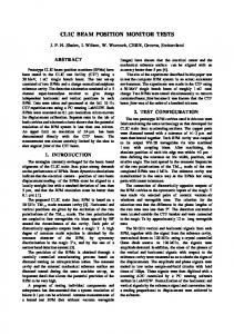
Analysis of the Filter Comparator The design and performance of the existing BPM front end will be considered as the baseline design for the continuous effort to improve and upgrade the APS beam diagnostics. A block diagram of the filter comparator is shown in Figure 1. The primary function of the filter-comparator unit is to convert the voltage impulse from the buttons into pulse modulated signals at 351.93 MHz, the ring’s rf frequency. It also compares the four rf signals to create a beam intensity signal and two deviation signals, one for the x-axis and one for the y-axis. The original filter-comparator design shown in Figure 1 uses 6 dB pads to match the button outputs and 2 dB pads to help match the input of the band-pass filters. The filters, hybrid comparator, and pads add up to a total insertion loss of 15 dB. This reduces the in-band power into the receiver to less than –8 dBm @100 mA with the standard fill pattern. The standard fill pattern is 10 mA in a cluster of 6 bunches followed by 90 mA in 25 triplets. The RFBPMs are presently configured to sample the 10 mA bunch of 6, or target cluster. A considerable dead time of hundreds of ns is necessary prior to the arrival of the target cluster to avoid the effects of time-domain side lobes and small reflections. The present goal is to fill the entire ring with singlets or triplets evenly spaced around the ring with as little as approximately 100 ns dead time between bunch trains.
to
A +B
L PF
AT T
AT T 18 0
ATT
bo
AT T
L PF
ti
AT T
L PF
BPF
Σ
18 0 A- B AT T
ATT
BPF
BPF
∆ x
∆ y
C +D 180 to
180
L PF
AT T
C -D DIV
T es t /T im in g
FIGURE 1. Filter-comparator block diagram (original design).
It is desirable to operate the system such that the maximum receiver input (+5 dBm) is realized in order to minimize the noise. The output noise of the receiver can be described as:
∆/Σ sensitivity = 1volt / 90 degrees
(1)
Phase jitter ∆θ = 1 / √SNR rads
(2)
Receiver output noise = Phase jitter x ∆/Σ sensitivity
(3)
The thermal noise power (kTB) for the 20 MHz bandwidth is –91 dBm. Since there are two channels, the noise is noncoherent and will sum for a total equivalent noise of –88 dBm. The other problem with this design is the time-domain side lobe caused by the phase response of the band-pass filters (27 dB down) specified at 60 dB. The side lobes and reflections become a problem when the storage ring is completely filled and there is minimum dead time between bunches. There are other problems with maintaining a system that is partitioned with the receiver front end located in the tunnel. It becomes very difficult to troubleshoot and isolate problems between the buttons and the receiver that arise during run periods.
Upgrade Design Approach The upgrade involves redesigning the in-tunnel filter-comparator units to improve insertion loss, return loss, and band-pass filter impulse response that presently limit the different fill patterns used at APS. The design improvements will be delineated into two phases. The first phase involves improving the signal strength and matching the output of the button electrodes into 50 ohms. The second phase will replace the existing filter comparator with improved components to minimize allowable cluster spacing. Reviewing Figure 1, we notice 8 dB of insertion loss due to the attenuators. These attenuate standing waves between the filter comparator and the button. The new design (Figure 2) will eliminate the need for the pads by carefully matching the components and, most importantly, the source.
to
A +B
BPF
Z /L P
Σ 18 0
bo
Z /L P
BPF
ti
Z /L P
BPF
18 0 A- B
∆x
∆
y
C +D 18 0
180 to
BPF
Z /L P
C -D
TE S T C O UP LE R
PHA SE A D JU S T
FIGURE 2. Filter-comparator block diagram (upgrade design).
The buttons have a very poor return loss when measured from the feedthrough side, which results in the reflection of 97% of the power. The button impedance is principally reactive with a small resistive component. To match the button’s impedance, an inductor is placed in parallel with the capacitive electrode. This effectively creates a parallel resonate circuit, driven by the image current source. This technique of resonating the capacitive pickup provides a controllable response in a compact electrode design (3). The total impedance (Ztotal) and voltage developed by the button (Vbutton) and can be described as follows: Ztotal = 1/(1/Zres + 1/Zcoax)
(4)
Vbutton = Ztotal × Iimage
(5)
As the equivalent impedance of the resonant circuit, Zres, increases, the total impedance, Ztotal, looks more like Zcoax or 50 ohms. The matching network will also include a low-pass filter that will provide an additional 46 dB of filtering at the second harmonic (704 MHz). The overall bandwidth will be maximized to 100 MHz at the –3dB power point in order to minimize the effect of button-to-button differences in capacitance and to ensure no interaction of the downstream band-pass filter. The implementation of the button-matching network will be considered phase 1 of the front-end upgrade and will be used together with the existing filter-comparator units. The second phase will involve replacing the 180-degree hybrid comparators and band-pass filters. The hybrid comparators will be implemented using a rat-race bridge topology, either laid out with mini coax or stripline. The rat-race hybrid will provide predictable and stable performance over the required 50 MHz bandwidth and will have less than 0.7 dB insertion loss and a 30 dB return loss at 352 MHz. The most difficult and critical part of phase 2 will be the implementation of the band-pass filters. The filters must be matched in phase and amplitude to ensure the vector addition and subtraction of the input signals. They must be phase matched to within 5 degrees over 20 cycles and amplitude matched better than 0.2 dB (100 µm) across the passband. They must also have time-domain side lobe rejection of 50 dB minimum at 100 ns or greater. Tests using band-pass filters with single-pole quarter-wave cavity resonators have had good success. The filters exhibit very low loss and can be matched to within 0.1 dB
of each other with minimum effort. The one problem encountered with the coaxial cavity is that we require the filter to ring down 50 dB in 100 ns so there is no interaction between bunches. Experiments have been conducted that trade off bandwidth for ring down time. At this time we have determined empirically that a 16 MHz bandwidth is the limit, due to the required data acquisition time of 100 ns. Ideally we need 100 ns of continuous wave 352 MHz output to the receiver with reflection and side lobes down a minimum of 60 dB. Another implementation of the band-pass filter that is being investigated is the transversal filter shown in Figure 3.
FIGURE 3. Transversal filter block diagram.
This device is basically a pulse repeater that delays each pulse or bunch of pulses by multiples of 2.84 nanoseconds with respect to each other. The result is a (SIN F/F)2 response that has good matching characteristics unit to unit and good cancellation over all frequencies and times. The filter must be designed such that a minimum of 24 pulses, or 24 × 2.84 ns, are generated, which will yield a 68 ns pulse train. This is the minimum number of pulses required due to the 50 ns integration time and timing considerations. It is desirable to increase the number of pulses, provided that the overall size requirements can be maintained. A prototype set of filters has been constructed, using coaxial cable delays, with favorable results. Presently we are trying to find a cost-effective way of implementing this design on standard low-cost microwave board materials. We are also investigating implementing the delay using lumped components in order to minimize the cost and size of the filter assembly. An alternative transversal filter implementation under investigation employs surface acoustic wave (SAW) band-pass filters. These filters exhibit high stability and reliability with good performance and no adjustments. This technology is available in the frequency and bandwidth required and has the same (SIN F/F)2 performance as the transversal filter described above. The insertion loss is typically 4 dB for a filter similar to those meeting our requirements. Such filters are commonly used in many receiver bandpass filter applications. Another important consideration of the upgrade will be the improvement of self-test capability, maintainability, and calibration of the RFBPM system. The test couplers will provide access to the input signals to aid in the troubleshooting and isolation of problems occurring during run periods. They will also be used as injection inputs for a selftest module that will provide input stimulus to an entire sector of BPMs during maintenance periods for calibration.
Preliminary Performance for Upgrade The upgrade described in Figure 2 was implemented in the APS storage ring with 16-MHz cavity band-pass filters and the M/A-COM H-9 monopulse comparator network located above the tunnel. The matching network improves the button’s return loss to the specified value at 352 MHz of 30 dB and results indicate better than 34 dB. The Smith chart in Figure 4 depicts the button and matching network after installation; it shows significant improvement over the button alone. Figure 5 gives the output of one button impedance matching network when driven by 6 bunches at 1.67 mA/bunch.
FIGURE 4. Measured impedance of a typical button electrode with matching network.
FIGURE 5. Output of impedance matching network with 6 bunches at 1.67 mA/bunch.
Figure 6 shows the sum of the 16 MHz BW cavity resonators into the receiver. The receiver output is seen in Figure 7 with the top trace being the Σ and the lower trace ∆/Σ. An overall improvement of 22 dB was realized from the original design. This is due to a 13.5 dB improvement of insertion loss from the filter comparator (15 dB– 1.5 dB) and a gain from the buttons of 8.5 dB.
FIGURE 6. Sum of the cavity band-pass FIGURE 7. Receiver output with 6 bunches filter with 6 bunches at 1.67 mA/bunch. at 1.67 mA/bunch.
CONCLUSION The testing to date is very encouraging, and most of the system specifications are satisfied. Phase 1 implementation is planned for the July 1998 shutdown for 9 sets of BPMs. Data logging studies over long periods are planned to prove stable operation. The final band-pass filter and comparator configuration implementation will follow early next year.
REFERENCES [1] [2]
[3]
Kahana, E., “Design of Beam Position Monitor Electronics for the APS Storage Ring,” Proceedings of the 3rd Accelerator Beam Instrumentation Workshop, AIP Conference Proceedings 252, pp. 235–240 (1992). Lenkszus, Frank R., Emmanuel Kahana, Allen J. Votaw, Glenn A. Decker, Youngjoo Chung, Daniel J. Ciarlette, Robert J. Laird, “Beam Position Monitor Data Acquisition for the Advanced Photon Source,” Proceedings of the 1993 Particle Accelerator Conference, pp. 1814–1816 (1993). Glen Lambertson, “Dynamic Devices-Pickups and Kickers,” AIP Conference Proceedings 153, Volume 2, pp. 1413–1442 (1987).