This paper describes the Advanced Photon Source. (APS) storage ring monopulse rf beam position monitor. (BPM) system upgrade. The present rf BPM system.
Proceedings DIPAC 2001 – ESRF, Grenoble, France
ADVANCED PHOTON SOURCE RF BEAM POSITION MONITOR
SYSTEM UPGRADE DESIGN AND COMMISSIONING
R. Lill, G. Decker, O. Singh
Advanced Photon Source, Argonne National Laboratory,
9700 South Cass Avenue, Argonne IL 60439 USA
Abstract This paper describes the Advanced Photon Source (APS) storage ring monopulse rf beam position monitor (BPM) system upgrade. The present rf BPM system requires a large dead time of 400 ns between the measured bunch and upstream bunch. The bunch pattern is also constrained by the required target cluster of six bunches of 7 mA minimum necessary to operate the receiver near the top end of the dynamic range. The upgrade design objectives involve resolving bunches spaced as closely as 100 ns. These design objectives require us to reduce receiver front-end losses and reflections. An improved trigger scheme that minimizes systematic errors is also required. The upgrade is in the final phases of installation and commissioning at this time. The latest experimental and commissioning data and results will be presented.
The filter comparator (Figure 1) is to be located 42 inches away from the buttons via matched silicon dioxide cables. The system is matched in phase and amplitude to insure the vector addition and subtraction of the input signals. The 180-degree hybrid comparator network described in Figure 1 has been implemented using a rat race hybrid topology. The rat race hybrid consists of three λ/4 and one 3λ/4 lengths of 70.7-ohm mini coax. The four lengths are connected together in a ring configuration yielding 50-ohm inputs and outputs. The bandwidth is extended from 20% to 30% by using a ferrite reversing coil on the 3λ/4 leg of the bridge. The hybrid network provides a low loss sum of all four inputs and excellent return loss on all ports.
1 INTRODUCTION The measurement of the APS storage ring beam position is accomplished by 360 rf BPMs located approximately every degree around the 1104-m circumference ring [1]. The rf BPM signal processing topology used is a monopulse amplitude-to-phase (AM/PM) technique for measuring the beam position in the x and y axes. A logarithmic amplifier channel measures the beam intensity. The rf BPM upgrade was proposed at BIW 1998 [2].
2 SYSTEM DESIGN Figure 1 is the block diagram for the monopulse rf BPM receiver front end. The matching networks are attached directly to 10-mm-diameter button electrodes [3]. The button matching network was designed to match the capacitively reactive button (0.25–j75 ohm) into 50 ohms in a 100-MHz, 3-dB bandwidth centered at 352 MHz. This matching network circuit has the response characteristics of a bandpass filter with the button’s capacitance (4.8 pf) integrated as part of the filter design. To match the button’s impedance, an inductor and resistor are placed in parallel with the capacitive electrode and the beam current source. The matching network circuit also includes a 3-pole, low-pass filter that attenuates the second harmonic (704 MHz) by 46 dB. The matching network typically improves the in-band signal strength by 5 dB. They also provide >25 dB return loss source match, in a 10-MHz bandwidth centered at 352 MHz.
180
Figure 1: BPM receiver front-end block diagram. The self-test input provides an input signal to test the comparator during maintenance periods. The input signal is split four ways and fed into the coupling arm of 15-dB directional couplers in each of the inputs. The new comparator can be operated with one input offset by 6 dB or with all inputs balanced. Resolving bunches spaced as closely as 100 ns and minimizing associated systematic errors required designing a bandpass filter that had nearly a rectangular time domain response. This [SIN F/F]2 frequency response was realized using the technique illustrated in Figure 2. The transversal filter is best explained in the time domain. The transversal filter
PM08
Posters Monday
Proceedings DIPAC 2001 – ESRF, Grenoble, France processes the input signal by splitting the signal and passing it though a series of delays and then recombining the outputs. The delays are chosen such that some frequencies will add (passband) and some frequencies will cancel (rejection band), thus establishing the filtering function. The 4-dB bandwidth (BW) can be calculated by taking the inverse of the total filter delay. Our design used delay multiples of 2.84 ns or 1/351.93 MHz, the storage ring rf frequency. The filter design has 24 delay paths and is centered at 351.93 MHz. The 4-dB bandwidth is equal to 24 × 2.84 ns = 68.2 ns or 14.7 MHz. In the frequency domain shown in Figure 3, the first side lobe is down 13 dB from the main lobe. The nulls will occur at a frequency interval of 14.7 MHz. The time domain response to six adjacent storage ring buckets filled with a total of 4 mA is shown in Figure 4. The time domain response is a rectangular burst with a side lobe rejection of 50 dB. The response has a flat top or constant input power into the receiver for the measurement. This is accomplished in our design by using unequal Wilkinson power dividers to compensate for the variation in delay loss. The construction of a single 24pulse transversal filter requires forty-six two-way unequal power dividers. The total length of the delay line is just less than 30 meters. The filter was designed and built using stripline laid out on Rogers RO4003/4403 laminate microwave board materials. The dielectric constant of the composite ceramic/glass material is 3.53 and the loss tangent is 0.004. This material has an excellent temperature stability rating and meets the gamma radiation requirements necessary to install them in the tunnel. The new filter comparator using the transversal filters has an overall insertion loss of 7.0 dB, which is an improvement of 8 dB over the existing system.
Figure 3: Transversal filter frequency response to single bunch with 8 mA.
Figure 4: Transversal filter time domain response (10-dB coupler).
Figure 2: Transversal filter illustration. The filter comparator output is fed through the tunnel penetration with 1/4-inch-diameter heliax cables and provides the mono pulse receiver inputs. The receiver is an integral part of the signal conditioning and digitizing unit (SCDU) with the receiver physically mounted on the VXI board [1].
Posters Monday
The sum data is peak detected, and the normalized position data is integrated on the SCDU shown in Figure 5. Both signals are digitized, and the data from the SCDU is then stored in registers. The upgrade also involved replacing the sum and position registers. The original register chip had a chronic failure mode that ranged from burning up completely to corrupting the data at certain bit patterns. The underling problem was related to the SCDU board layout. The I/O and clock lines were going negative or below the ground level (-1.5 volts for about 20 ns), which caused the chip to latch-up and/or overheat. The replacement register chip has a 2.5-volt undershoot rating and is a pin-for-pin replacement. This part of the upgrade has been operational for almost two years with good results. The registers are read periodically by the memory scanner in the same VXI crate via the local bus. The memory scanner then conditions the digital data and sends it to the appropriate systems.
PM08
181
Proceedings DIPAC 2001 – ESRF, Grenoble, France commissioning of the new timing system and further studies.
Figure 5: Signal conditioning and digitizing unit block diagram. The BPM timing was also improved as part of the BPM upgrade. The original system utilized a beam-based trigger that was derived from the sum video signal. The external arm signal was used to select the bunch to be measured, and the threshold of the SCDU log video sum signal triggered the event. This timing scheme is susceptible to trigger walk and bunch-to-bunch spacing, which could change the shape of the trigger edge. The upgrade design leverages off an existing timing module called Bunch Clock Generator (BCG) [4] to generate the BPM trigger. The BCG loads the bunch pattern into RAM at injection and then shifts out the data one bit at a time at 352 MHz. The shifting is synchronized with the revolution clock such that the bit sequence starts over at each revolution. The upgrade was designed to operate with the original beam based trigger or the external BCG signal.
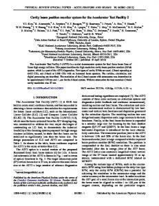
3 STATUS AND RESULTS Presently one of the 40 APS sectors (nine BPMs) have been implemented with the full upgrade. The results shown in Figure 6 indicate typical crosstalk between bunches as a function of bunch spacing. First 5 mA were injected into a single bunch and the orbit corrected using all but the upgraded BPMs. Then a second bunch was injected on the opposite side of the ring and the timing for the upgraded units was set to trigger at that point. Finally, while measuring the beam position of this second bunch, a third bunch was injected at a fixed time preceding the second bunch. The variation of the position readback was then recorded as a function of charge in the third bunch. This experiment was repeated seven more times using different delay values for the third bunch, as indicated by the legend in Figure 6. While the crosstalk for the upgrade electronics is acceptable, it was discovered that the upgrade of the timing alone improved performance significantly in comparison to the beam-based trigger in use to date. It appears that the trigger walk is a more important factor for bunch-to-bunch crosstalk than the long decay time of the bandpass filter, as originally theorized. The timing system upgrade is complete and is being commissioned during the May 2001 operating period. The new filter comparator unit upgrade is on hold pending
182
Figure 6: Bunch spacing systematic errors.
ACKNOWLEDGEMENTS The authors would like to acknowledge the contribution and leadership that John Galayda provided. This work is supported by U.S. Department of Energy, Office of Basic Energy Science under Contract No. W-31-109-ENG-38.
REFERENCES [1] E. Kahana, “Design of Beam Position Monitor Electronics for the APS Storage Ring,” Proceedings of the 3rd Accelerator Beam Instrumentation Workshop, AIP Conference Proceedings 252, pp. 235-240 (1992). [2] R. Lill, G. Decker, “Advanced Photon Source Monopulse RF Beam Position Monitor Front-end Upgrade,” Proceedings of the 8th Accelerator Beam Instrumentation Workshop, AIP Conference Proceedings 451, pp. 318-324 (1998). [3] E. Plouviez, S. Eandi, “A Fast Global Feedback System to Correct the Beam Position Deviation in the ESRF Storage Ring,” Proceedings of the 3rd European Workshop, DIPAC 97 Conference Proceedings, pp. 79-81 (1997). [4] F. Lenkszus, R. Laird, “A Bunch Clock for the Advanced Photon Source,” Proceedings of the 1997 Particle Accelerator Conference, Volume 2, pp. 2490-2492 (1997).
PM08
Posters Monday