Aug 20, 2010 - In this PhD thesis the problem of detection and classification of ... 1.2 State-of-the-Art . . ..... quality information of local decisions using the bootstrap principle [44 ..... complex wall effects, violation of the far-field assumption and/or ..... only if a strong reflection at location (i0,j0) is observed in each radar image.
Advances in Detection and Classification for Through-the-Wall Radar Imaging
Vom Fachbereich 18 Elektrotechnik und Informationstechnik der Technischen Universit¨at Darmstadt zur Erlangung der W¨ urde eines Doktor-Ingenieurs (Dr.-Ing.) genehmigte Dissertation
von Christian Debes, M.Sc. geboren am 27.02.1981 in Groß-Gerau
Referent: Korreferent: Tag der Einreichung: Tag der m¨ undlichen Pr¨ ufung:
Prof. Dr.-Ing. Abdelhak M. Zoubir Prof. Dr. Moeness G. Amin 25.05.2010 20.08.2010
D 17 Darmstadt, 2010
I
Acknowledgments I wish to thank all people who have helped and inspired me during my doctoral study. I especially want to thank Prof. Dr.-Ing. Abdelhak Zoubir for his supervision. It is truly a pleasure being supervised by an outstanding researcher who shows such a high degree of enthusiasm and motivation. Prof. Zoubir provided me with an inspiring mix of freedom in research and guidance which made my time as a PhD student a pleasure. I wish to thank Prof. Dr. Moeness Amin for his supervision, guidance and exceptional hospitality when visiting Villanova University. I benefitted greatly from our interactions, and I am delighted to have such a renowned researcher as my co-advisor. I also want to thank Prof. Dr.-Ing. Thomas Hartkopf, Prof. Dr.-Ing. Rolf Jakoby and Prof. Dr.-Ing. Ralf Steinmetz who acted as chair and examiners in the PhD committee. My thanks go to my colleagues at the Signal Processing Group at TU Darmstadt. I was, and still am, very happy to work in such a convivial environment. Thanks to Raquel Fandos, Philipp Heidenreich, Marco Moebus, Stefan Leier, Weaam Alkhaldi, Michael Muma, Yacine Chakhchoukh, Ahmed Mostafa, Fiky Suratman, Zhihua Lu, Waqas Sharif and Gebremichael Teame, as well as Renate Koschella and Hauke Fath. I would also like to thank the former PhD students and postdocs Uli Hammes, Eric Wolsztynski, Chris Brown, Luke Cirillo, Ramon Brcic, Christopher Kallenberger and Said Aouada. A special thanks to everybody at CAC at Villanova University for fruitful discussions and great hospitality. Thanks to Fauzia Ahmad, Janice Moughan, Pawan Setlur and Graeme Smith. I was happy to supervise great students whose efforts have contributed to this thesis. My sincere thanks go to Jesper Riedler, Christian Weiß, J¨ urgen Hahn, Feng Yin, Michael Leigsnering and Nils Bornhorst. I wish to thank my parents Ulrike & Hans Debes for their unconditional love and support throughout my life. I would also like to thank the rest of my family, especially Stephanie, Peter, Robin and Alexandre. Finally, I am most grateful to my wife Katrin and my sons Cedric and Liam for their understanding, love, encouragement, support and joy. Darmstadt, 25.08.2010
III
Kurzfassung In dieser Doktorarbeit wird das Problem der Detektion und Klassifikation station¨arer Ziele betrachtet. Die Anwendung konzentriert sich auf radarbildgebende Verfahren durch lichtundurchl¨assige Materialien, wie etwa W¨ande. Es wird eine Konstellation betrachtet, bei der eine dreidimensionale Szene aus verschiedenen Blickwinkeln abgebildet wird. Hierdurch k¨onnen unerw¨ unschte Reflektionen und Rauschen unterdr¨ uckt und die Zieldetektierbarkeit verbessert werden. Im Bereich der Zieldetektion werden zentralisierte und dezentralisierte Ans¨atze zur gleichzeitigen Bildfusion und Detektion betrachtet. Insbesondere wird der f¨ ur die Praxis relevante Fall analysiert, in dem kein Wissen u ¨ ber die Bildstatistiken vorhanden ist und R¨ uckschl¨ usse nur aus den erfassten Daten gezogen werden k¨onnen. Zur Probleml¨osung wird ein adaptiver Detektor eingef¨ uhrt, der sich nichtstation¨aren Statistiken anpasst. Optimale Konfigurationen dieses Detektors werden basierend auf morphologischen Operatoren hergeleitet. Hierdurch wird eine systematisierte und zuverl¨assige Zieldetektion erreicht. In dezentralisierten Ans¨atzen werden lokale Entscheidungen zu einem Fusionszentrum u ¨ bertragen, das daraufhin eine globale Entscheidung trifft. In diesen Szenarien ist das Konzept der Konfidenzinformation lokaler Entscheidungen von fundamentaler Bedeutung, um akzeptable Detektionsergebnisse zu erhalten. Konfidenzinformationen basieren klassischerweise auf vorhandenem Wissen u ¨ ber Bildstatistiken oder Eigenschaften der lokalen Detektoren, die h¨aufig jedoch unbekannt sind. Ein neuartiges, adaptives Fusionsverfahren wird zur L¨osung vorgeschlagen. Es verwendet das Bootstrap-Verfahren um systematisch Konfidenzinformationen der lokalen Detektoren zu sch¨atzen. Im Bereich der Zielklassifikation wird ein allgemeines Rahmenwerk, bestehend aus Segmentierung, Merkmalserfassung und Entscheidung vorgestellt. Die einzelnen Schritte dieser Struktur werden an die Anwendung radarbildgebender Verfahren durch lichtundurchl¨assige Materialien angepasst. Der Fokus liegt hierbei auf der Vorstellung statistischer und geometrischer Merkmalss¨atze, basierend auf Superquadrics. Es wird demonstriert, dass die meisten Merkmalss¨atze abh¨angig von System- oder Szenenparametern, wie etwa der Systemaufl¨osung oder der Distanz zum Ziel sind. Kompensationsmethoden, die eine aufl¨osungsunabh¨angige Merkmalserfassung erm¨oglichen werden als Konsequenz hieraus hergeleitet.
IV Alle vorgestellten Verfahren werden sowohl mit simulierten, als auch mit experimentellen Daten evaluiert. Letztere stammen von einem dreidimensionalen Radarbildgebungssystem unter Verwendung breitbandiger Strahlformung.
V
Abstract In this PhD thesis the problem of detection and classification of stationary targets in Through-the-Wall Radar Imaging is considered. A multiple-view framework is used in which a 3D scene of interest is imaged from a set of vantage points. By doing so, clutter and noise is strongly suppressed and target detectability increased. In target detection, centralized as well as decentralized frameworks for simultaneous image fusion and detection are examined. The practical case when no prior knowledge on image statistics is available and all inference must be drawn from the data at hand is specifically considered. An adaptive detection scheme is proposed which iteratively adapts in a non-stationary environment. Optimal configurations for this scheme are derived based on morphological operations which allow for automatic and reliable target detection. In a decentralized framework, local decisions are transmitted to a fusion center to compile a global decision. In these scenarios, the concept of confidence information of local decisions is crucial to obtain acceptable detection results. Confidence information is classically based on prior knowledge on either the image statistics or local detector performance which generally are unknown in practice. A novel adaptive fusion scheme based on the bootstrap is proposed to automatically extract confidence information of local decisions given the acquired data at hand. In target classification a general framework consisting of segmentation, feature extraction and target discrimination is proposed. The adaption of all these techniques to the application of Through-the-Wall Radar Imaging is investigated, whereby the focus is set on the feature extraction step. A combination of statistical and geometrical features based on superquadrics is proposed. It is shown that most features depend on system and scene parameters such as system resolution and target distance. Compensation methods to allow for resolution-independent feature extraction are consequently derived. All proposed methods are evaluated using simulated as well as real data measurements obtained from three-dimensional imaging measurements using wideband sum-and-delay beamforming.
VII
Contents 1 Introduction and Motivation 1.1 Motivation . . . . . . . . . . 1.2 State-of-the-Art . . . . . . . 1.3 Contributions . . . . . . . . 1.4 Publications . . . . . . . . . 1.5 Thesis overview . . . . . . .
. . . . .
. . . . .
. . . . .
. . . . .
. . . . .
. . . . .
. . . . .
. . . . .
. . . . .
. . . . .
. . . . .
. . . . .
. . . . .
. . . . .
. . . . .
2 Image formation and Statistical Analysis 2.1 Beamforming in Through-the-Wall Radar Imaging . . . 2.2 Statistical analysis of Through-the-Wall Radar Images 2.2.1 Experimental Setup . . . . . . . . . . . . . . . . 2.2.2 Empirical Study . . . . . . . . . . . . . . . . . . 2.3 Conclusions . . . . . . . . . . . . . . . . . . . . . . . .
. . . . .
. . . . .
. . . . .
. . . . .
. . . . .
. . . . .
. . . . .
. . . . .
. . . . .
. . . . .
. . . . .
. . . . .
. . . . .
. . . . .
3 Centralized Target Detection 3.1 Motivation . . . . . . . . . . . . . . . . . . . . . . . . . . . . . . . . 3.2 Simple Thresholding Technique . . . . . . . . . . . . . . . . . . . . 3.3 The Neyman-Pearson Test . . . . . . . . . . . . . . . . . . . . . . . 3.4 Adaptive Target Detection . . . . . . . . . . . . . . . . . . . . . . . 3.4.1 Motivation . . . . . . . . . . . . . . . . . . . . . . . . . . . . 3.4.2 Simplified Adaptive Target Detection . . . . . . . . . . . . . 3.4.3 Adaptive Target Detection Using Morphological Operations 3.4.4 Conditions for Convergence . . . . . . . . . . . . . . . . . . 3.4.5 Optimizing the Structuring Element . . . . . . . . . . . . . 3.5 Experimental Results . . . . . . . . . . . . . . . . . . . . . . . . . . 3.5.1 Single-view imaging . . . . . . . . . . . . . . . . . . . . . . . 3.5.2 Multiple-view imaging . . . . . . . . . . . . . . . . . . . . . 3.5.3 3D imaging . . . . . . . . . . . . . . . . . . . . . . . . . . . 3.6 Conclusions . . . . . . . . . . . . . . . . . . . . . . . . . . . . . . . 4 Decentralized Target Detection 4.1 Motivation . . . . . . . . . . . . . . . . . . . . . . . . . . . . . 4.2 Static Decision Fusion . . . . . . . . . . . . . . . . . . . . . . 4.3 Adaptive Decision Fusion . . . . . . . . . . . . . . . . . . . . . 4.3.1 Decision Fusion using the iterative detection approach 4.3.2 Decision Fusion using the bootstrap . . . . . . . . . . . 4.3.3 Simulation Results . . . . . . . . . . . . . . . . . . . .
. . . . . .
. . . . . .
. . . . . .
. . . . .
. . . . .
. . . . . . . . . . . . . .
. . . . . .
. . . . .
1 1 2 3 3 5
. . . . .
7 7 11 11 12 20
. . . . . . . . . . . . . .
23 23 24 26 27 27 28 32 34 38 40 41 45 46 50
. . . . . .
51 51 52 53 54 55 56
VIII 4.4 Experimental Results . . . . . . 4.4.1 Static decision fusion . . 4.4.2 Adaptive decision fusion 4.5 Conclusions . . . . . . . . . . .
Contents . . . .
. . . .
. . . .
. . . .
. . . .
. . . .
. . . .
. . . .
. . . .
. . . .
5 Classification Approaches 5.1 Motivation . . . . . . . . . . . . . . . . . . . . . . 5.2 Segmentation . . . . . . . . . . . . . . . . . . . . 5.2.1 Segmentation using ICM . . . . . . . . . . 5.2.2 Segmentation using the Level Set Method 5.3 Feature Extraction . . . . . . . . . . . . . . . . . 5.3.1 Dependence on target resolution . . . . . . 5.3.2 Statistical Feature Extraction . . . . . . . 5.3.3 Geometrical Feature Extraction . . . . . . 5.3.3.1 Rotation and global deformations 5.4 Experimental Results . . . . . . . . . . . . . . . . 5.5 Conclusions . . . . . . . . . . . . . . . . . . . . . 6 Conclusions and Future work 6.1 Conclusions . . . . . . . . . . . . . . . 6.1.1 Centralized Target Detection . . 6.1.2 Decentralized Target Detection 6.1.3 Classification . . . . . . . . . . 6.2 Future Work . . . . . . . . . . . . . . . 6.2.1 Beamforming . . . . . . . . . . 6.2.2 Centralized Target Detection . . 6.2.3 Decentralized Target Detection 6.2.4 Classification . . . . . . . . . . 6.2.5 Wall Removal . . . . . . . . . .
. . . . . . . . . .
. . . . . . . . . .
. . . . . . . . . .
. . . . . . . . . .
. . . . . . . . . .
. . . . . . . . . .
. . . .
. . . . . . . . . . .
. . . . . . . . . .
. . . .
. . . . . . . . . . .
. . . . . . . . . .
. . . .
. . . . . . . . . . .
. . . . . . . . . .
. . . .
. . . . . . . . . . .
. . . . . . . . . .
. . . .
. . . . . . . . . . .
. . . . . . . . . .
. . . .
. . . . . . . . . . .
. . . . . . . . . .
. . . .
. . . . . . . . . . .
. . . . . . . . . .
. . . .
. . . . . . . . . . .
. . . . . . . . . .
. . . .
. . . . . . . . . . .
. . . . . . . . . .
. . . .
. . . . . . . . . . .
. . . . . . . . . .
. . . .
. . . . . . . . . . .
. . . . . . . . . .
. . . .
57 58 59 61
. . . . . . . . . . .
63 63 64 64 66 67 68 69 70 71 73 76
. . . . . . . . . .
79 79 79 79 80 80 80 81 81 82 83
Appendix
85
List of Acronyms
87
List of Symbols
89
Bibliography
93
Curriculum vitae
101
1
Chapter 1 Introduction and Motivation Through-the-Wall Radar Imaging (TWRI) is an emerging technology [1–6], allowing to “see” through visually opaque material such as walls. It has numerous civilian, law enforcement and military applications making it a highly desirable tool in, for example, police and firefighter missions or search and rescue operations. TWRI can be used to detect buried people after natural disasters, e.g. earthquakes. It allows police units to detect and locate hostages, hostage-takers and weapons in a hostage crisis before even entering the building and allows to detect and classify concealed weapons and explosives in military actions or for homeland security purposes. In all these applications, it is the ultimate aim to use radio frequency (RF) emission and reception to gain vision into scenes which otherwise are nonaccessible physically, optically, acoustically, or thermally. Images obtained from behind walls using electromagnetic propagation are subject to strong distortions. Automatic schemes for target detection and classification thus are of high practical interest in this area. It is the aim of this thesis to design such schemes that need no or only marginal prior knowledge on scene statistics and that simultaneously perform fusion and detection on a set of images obtained from multiple vantage points. Developed classification schemes have to be invariant to system and scene parameters, e.g. system resolution and target distance to allow for reliable results in a variety of scenarios.
1.1
Motivation
Automatic detection of humans and objects of interest, e.g., concealed weapons or explosive material, is of high practical interest [4,5] and fundamental to follow-on tasks of target classification and tracking, image interpretation and understanding. Little work thus far has been done in applying the principles of detection and classification theory to the special characteristics of TWRI and indoor radar images. The image statistics depend, among other things, on the target electric properties, size, shape, and surroundings. With several possible indoor targets such as human, furniture, and appliances, as well as the influence of wall impairing and multipath propagation effects, robust detection in which the detector adapts itself to the changing and/or unknown characteristics of the data is crucial.
2
Chapter 1: Introduction and Motivation
A set of TWRI images acquired from the same scene using different vantage points has been shown [6,7] to increase detectability of targets. The question arises, however, how to automatically perform simultaneous image fusion [8–10] and target detection to obtain a single binary reference image which indicates the presence or absence of targets. Practical methods have to take into account that the image statistics may differ dramatically when using different vantage points. The radar cross section (RCS) of targets is generally not invariant to rotation. Further, in a typical indoor scenario it is likely that targets may only be visible from few vantage points and are shadowed from others. Classification is a follow-on task to detection. The aim is to divide a TWRI image into a finite set of segmented objects which are labelled according to a certain class that may depend on target material or shape, for example. This so called object occupancy map can then be used by an image analyst to get a sophisticated description of the targets being present in the scene of interest. One important issue in target classification is robustness with respect to target coordinates and system parameters. TWRI images change in pixel intensity as well as in shape when moving the target with respect to the imaging system and/or change system parameters such as bandwidth and crossrange resolution. Thus, a practical TWRI classification system has to be robust to changes in resolution.
1.2
State-of-the-Art
TWRI involves cross-disciplinary research in electromagnetic propagation [11], antenna and waveform design [12], beamforming [6,13–18], wall compensation [19–21] and image processing [22–24] among others. Only little work has been accomplished in the area of target detection in TWRI. Most contributions in this area deal with moving targets, where Doppler shifts can be considered [25–28]. To the best of our knowledge the only contribution, beside our own contributions [7,29–35] where detection of stationary targets for TWRI is performed in the image domain is considered by Ahmad and Amin in [6, 36] where a simple thresholding and multiplication scheme is used. Classically the problem of target detection under unknown and possibly varying statistics in the image domain could be treated by constant false-alarm rate (CFAR) detectors [37–39], such as cell-averaging CFAR (CACFAR) [40] or order statistics CFAR (OSCFAR) [38, 41] methods. These methods aim at providing a constant false-alarm rate while the statistics may be time- and/or spacevarying. The drawback of these approaches is that important parameters which have a strong impact on the detection result such as cell size and guard cell size in CACFAR or the percentile in OSCFAR have to be
1.3 Contributions
3
chosen beforehand. Given the aim of automatic target detection, it is undesirable to tune parameters, other than the false-alarm rate to be achieved. The only work beside our own contributions [42,43] dealing with target classification in TWRI is, to the best of our knowledge, by Rosenbaum and Mobasseri in [24] where the principal component analysis (PCA) is applied. However, this approach is practically limited as the authors provide features which are not resolution-independent.
1.3
Contributions
The contributions of this thesis are as follows:
• Centralized Target Detection: An adaptive target detector is developed, which is applicable for stationary target detection in TWRI. The detector does not assume prior knowledge of the image statistics and allows to adapt to spacevarying statistics. It is derived in detail, considering conditions of convergence as well as optimal configurations. The detector can be used in single- as well as multiple-view imaging scenarios. • Decentralized Target Detection: Existing decentralized detection schemes which assume prior knowledge of the image statistics are extended to cope with unknown and varying statistics. Further, a new technique to obtain confidence or quality information of local decisions using the bootstrap principle [44, 45] is introduced. It improves the performance of classical decentralized target detectors at the cost of slightly increased bandwidth requirements. • Target Classification: A target classification framework, consisting of segmentation, feature extraction and classification is formulated and adapted to the application of TWRI. The usage of geometrical and statistical features is exploited and analyzed. Further, the problem of system- and scene-independent features is considered. Transformation schemes that allow to obtain features which are independent of system resolution and target distance are derived.
1.4
Publications
The following publications have been produced during the period of PhD candidacy.
4
Chapter 1: Introduction and Motivation
Book chapter • C. Debes, A. M. Zoubir. Detection approaches in Through-Wall Radar Imaging, in Through-the-Wall Radar Imaging, CRC Press, to appear.
Internationally Refereed Journal Articles • C. Debes, J. Hahn, A. M. Zoubir and M. G. Amin. Segmentation, Feature Extraction and Discrimination of Targets in Through-the-Wall Radar Imaging. IEEE Transactions on Geoscience and Remote Sensing, submitted. • C. Debes, J. Riedler, A. M. Zoubir, M. G. Amin. Adaptive Target Detection with Application to Through-the-Wall Radar Imaging. IEEE Transactions on Signal Processing, submitted. • C. Debes, M. G. Amin, A. M. Zoubir. Target Detection in Single- and MultipleView Through-the-Wall Radar Imaging. IEEE Transactions on Geoscience and Remote Sensing. vol. 47(5), pp. 1349 - 1361, May 2009.
Internationally Refereed Conference Papers • C. Debes, C. Weiss, A. M. Zoubir, M. G. Amin. Wall-Clutter Mitigation using Cross-Beamforming in Through-the-Wall Radar Imaging. 18th European Signal Processing Conference (EUSIPCO), to appear. • C. Debes, A. M. Zoubir. Image-Domain based Target Detection under Model Uncertainties in Through-the-Wall Radar Imaging. American Electromagnetics Conference, Ottawa, Canada, July 2010, to appear. • C. Debes, C. Weiss, A. M. Zoubir, M.G. Amin. Distributed Target Detection in Through-the-Wall Radar Imaging using the Bootstrap. In Proceedings of the 35th IEEE International Conference on Acoustics, Speech and Signal Processing (ICASSP), pp. 3530 - 3533, Dallas, TX, USA, March 2010. • C. Debes, J. Hahn, A. M. Zoubir, M.G. Amin. Feature Extraction in Throughthe-Wall Radar Imaging. IEEE International Conference on Acoustics, Speech and Signal Processing (ICASSP), pp. 3562 - 3565, Dallas, TX, USA, March 2010. • C. Debes, A. M. Zoubir, M.G. Amin, Optimal Decision Fusion in Through-theWall Radar Imaging. In Proceedings of the IEEE Workshop on Statistical Signal Processing (SSP), Cardiff, UK, August 2009
1.5 Thesis overview
5
• C. Debes, J. Riedler, M. G. Amin, A. M. Zoubir. Iterative Target Detection Approach for Through-the-Wall Radar Imaging. In Proceedings of the 34th IEEE International Conference on Acoustics, Speech and Signal Processing (ICASSP), pg. 3061 - 3064 , Taipei, Taiwan, April 2009. • C. Debes, M. G. Amin, A. M. Zoubir. Target Detection in Multiple-Viewing Through-the-Wall Radar Imaging. In Proceedings of the 28th IEEE International Geoscience & Remote Sensing Symposium (IGARSS), Vol. 1, pp. 173-176, Boston MA, USA, July 2008. • C. Debes, R. Engel, A. M. Zoubir, A. Kraft. Quality assessment of synthetic aperture sonar images. In Proceedings of the IEEE OCEANS ’09, Bremen, Germany. • C. Debes, A. M. Zoubir. The recursive maximum likelihood algorithm for nonstationary signals. In Proceedings of the 33rd IEEE International Conference on Acoustics, Speech and Signal Processing (ICASSP), pp. 3777 - 3780, Las Vegas NV, USA, March 2008. • C. Debes, A. M. Zoubir. Bootstrapping autoregressive plus noise processes. In Proceedings of the 2nd IEEE International Workshop on Computational Advances in Multi-Sensor Adaptive Processing, pp. 53 - 56, St. Thomas, US Virgin Islands, December 2007.
1.5
Thesis overview
The thesis outline is as follows: Chapter 2 describes the image formation/beamforming process used to obtain three-dimensional TWRI images. It further introduces the experimental setup as well as a statistical analysis of typical TWRI images. Chapter 3 considers the problem of centralized target detection in TWRI, where individual TWRI systems are allowed to send raw image data to a global detector. An adaptive target detector is developed and successfully applied to experimental data. In Chapter 4 the detection framework is modified to a decentralized scheme, where individual TWRI systems are only allowed to send compressed information to a fusion center. After adapting existing detectors to cope with unknown image statistics the problem of confidence information of local decisions is treated. A new technique is proposed which allows to extract confidence or quality information based only on the data at hand.
6
Chapter 1: Introduction and Motivation
Target classification is considered in Chapter 5. A classification framework for TWRI is introduced. Further, the problem of resolution-independent features describing target objects is tackled. Conclusions are drawn in Chapter 6 and an outlook for future work is presented.
7
Chapter 2 Image formation and Statistical Analysis In this chapter image formation for TWRI is discussed. We hereby consider wideband sum-and-delay beamforming [6] used to obtain a 3D intensity map of the scene of interest. Further, a statistical analysis of TWRI images is provided based on an empirical study. This includes a description of the experimental setup used throughout this thesis.
2.1
Beamforming Imaging
in
Through-the-Wall
Radar
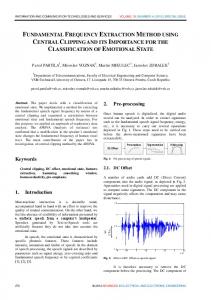
Beamforming describes the process of how to obtain an image or intensity map out of signals received by an antenna array. There exist many approaches for beamforming for TWRI applications [46]. This includes tomographic approaches [13–15] where the image formation is seen as an inverse scattering problem, differential SAR [47] and adaptive beamformers [18, 48]. In this thesis we restrict ourselves to wideband delay and sum beamforming [6]. However, we remark that the proposed detection and classification techniques introduced and derived in Chapters 3, 4 and 5 are postprocessing methods and are therefore independent of the actual beamforming process. In the following, we consider the same scheme as in [18], which has a strong link to high resolution image reconstruction in inverse synthetic aperture radar (ISAR) [49,50]. For simplicity the imaging scheme is first derived for freespace and then extended to imaging behind a homogeneous wall. We consider known wall parameters for beamforming. References [19–21] describe methods for estimating unknown wall parameters. In the following we consider a line array for simplicity, acquiring a two-dimensional image. This setup can be extended to two-dimensional arrays which will be used in the experimental setup in Section 2.2.1. We consider K transceivers, being placed at vk , k = 0, ..., K − 1, imaging a scene which is described by a local coordinate system (u′, v ′ ) as shown in Figure 2.1. Then, the distance from the k-th transceiver can be approximated by [18] Rk (u′ , v ′) ≈ Rk (0, 0) + u′ cos ϕk − v ′ sin ϕk
(2.1)
8
Chapter 2: Image formation and Statistical Analysis
v
v′
vk
Rk (u′p , vp′ ) (u′p , vp′ ) Rk (0, 0) ϕk
u, u′
R v1 Imaged Scene
v0
Figure 2.1. Beamforming scheme for high resolution radar imaging
where Rk (0, 0) denotes the distance from the k-th transceiver to the center of the scene and ϕk is the respective angle, as shown in Figure 2.1. Thus, � � vk −1 ϕk = sin (2.2) Rk (0, 0) where vk is the position of the k-th transceiver with respect to the array center. Consequently, the two-way propagation delay is given by τk (u′ , v ′ ) ≈
2 (Rk (0, 0) + u′ cos ϕk − v ′ sin ϕk ) c
(2.3)
with c denoting the propagation speed. Assume now a single point target being present at (u′p , vp′ ). Its distance from the k-th transceiver as well as the corresponding two-way propagation delay are given by Rk (u′p , vp′ ) ≈ Rk (0, 0) + u′p cos ϕk − vp′ sin ϕk � 2 Rk (0, 0) + u′p cos ϕk − vp′ sin ϕk τk (u′p , vp′ ) ≈ c
(2.4) (2.5)
9
2.1 Beamforming in Through-the-Wall Radar Imaging
When using a stepped-frequency approach [6], a wideband pulse is approximated by a finite number of narrowband pulses. The image formation using a sum and delay beamformer is then the summation ′
′
I(u , v ) =
P −1 X L−1 K−1 X X
Γ(u′p , vp′ )e−jωl (τk (u ,v )−τk (up ,vp )) ′
′
′
′
(2.6)
p=0 l=0 k=0
where ωl is the l-th frequency bin and P , L and K denote the number of targets, frequency bins and array elements, respectively. Further, Γ(u′p , vp′ ) is the complex ′ ′ reflectivity of the p-th target. The complex value Γ(u′p , vp′ )e−jωlτk (up ,vp ) can be obtained via matched filtering as described in [6]. Reducing the problem to the case of a single point target (P = 1) at (u′0, v0′ ) yields ′
′
I(u , v ) =
Γ(u′0, v0′ )
= Γ(u′0, v0′ )
L−1 K−1 X X
l=0 k=0 L−1 X K−1 X
e−jωl(τk (u ,v )−τk (u0 ,v0 )) ′
e−j
2ωl c
′
′
′
(2.7)
((u′ −u′0 ) cos ϕk −(v′ −v0′ ) sin ϕk )
(2.8)
l=0 k=0
Using the notation ωl = ω0 + l∆ω, where ω0 is the lowest used frequency, the acquired complex image can be written as I(u′ , v ′ ) = Γ(u′0 , v0′ ) = Γ(u′0 , v0′ )
L−1 K−1 X X
l=0 k=0 L−1 X K−1 X
e−j
2(ω0 +l·∆ω) ((u′ −u′0 ) cos ϕk −(v′ −v0′ ) sin ϕk ) c
e−j
2ω0 ((u′ −u′0 ) cos ϕk −(v′ −v0′ ) sin ϕk ) c
l=0 k=0
e−j =
(2.9)
×
2l∆ω ((u′ −u′0 ) cos ϕk −(v′ −v0′ ) sin ϕk ) c
Γ(u′0 , v0′ )
K−1 X
e−j
2ω0 ((u′ −u′0 ) cos ϕk −(v′ −v0′ ) sin ϕk ) c
k=0
L−1 X
e−j
×
2l∆ω ((u′ −u′0 ) cos ϕk −(v′ −v0′ ) sin ϕk ) c
l=0
= Γ(u′0 , v0′ )
K−1 X
e−j
2ω0 ((u′ −u′0 ) cos ϕk −(v′ −v0′ ) sin ϕk ) c
k=0
−j (L−1)∆ω ((u′ −u′0 ) cos ϕk −(v′ −v0′ ) sin ϕk ) c
e sin sin
×
×
L∆ω ((u′ − u′0 ) cos ϕk − (v ′ − v0′ ) sin ϕk ) c � ∆ω ′ − u′ ) cos ϕ − (v ′ − v ′ ) sin ϕ ) ((u k k 0 0 c
�
which in fact represents a spatial convolution of the target reflectivity with the system point spread function (PSF). In wideband sum-and-delay beamforming for TWRI [6], the summation over all frequencies and array elements still holds as per Equation (2.6), but the delay from the
10
Chapter 2: Image formation and Statistical Analysis
k-th array element to a point (u′p , vp′ ) in the local scene coordinate system now has to incorporate the propagation through the wall as [6] √ τk,wall (u′p , vp′ ) = (Rk,air,1 (u′p , vp′ ) + ǫRk,wall (u′p , vp′ ) + Rk,air,2 (u′p , vp′ ))/c (2.10) where ε denotes the dielectric constant of the wall and Rk,air,1 (u′p , vp′ ), Rk,wall(u′p , vp′ ) and Rk,air,2 (u′p , vp′ ) represent respectively the traveling distances of the electromagnetic wave from the k-th antenna to point (u′p , vp′ ) before, through and beyond the wall. u (u′p , vp′ )
R
k,
ai r,
2
111111111111 000000000000 000000000000 111111111111 000000000000 111111111111 000000000000 111111111111 000000000000 111111111111 000000000000 111111111111 000000000000 111111111111 000000000000 111111111111 ϕ 000000000000 111111111111 000000000000 111111111111 000000000000 111111111111 000000000000 0000111111111111 1111 0000 1111 0000 ϕ 1111 0000 1111 0000 0000000001111 111111111 000000000 111111111 ϕ 000000000 111111111 000000000 111111111 000000000 111111111 000000000 111111111 000000000 111111111 000000000 111111111 k,I
R
k,
wa ll
uoff + d
Wall
k,I
R
k,
ai r,
1
uoff
k,R
v
vk Figure 2.2. Propagation before, through and beyond a homogeneous wall The travelling distances Rk,air,1 (u′p , vp′ ), Rk,wall (u′p , vp′ ) and Rk,air,2 (u′p , vp′ ) can be estimated as [6] uoff (2.11) Rk,air,1 (u′p , vp′ ) = cos(ϕk,I (u′p , vp′ )) d Rk,wall (u′p , vp′ ) = (2.12) cos(ϕk,R (u′p , vp′ )) u′p − uoff − d ′ ′ (2.13) Rk,air,2 (up , vp ) = cos(ϕk,I (u′p , vp′ )) where uoff is the standoff distance from the system to the wall and ϕk,I (u′p , vp′ ) and ϕk,R(u′p , vp′ ) are the angle of incidence and refraction, respectively. The corresponding
2.2 Statistical analysis of Through-the-Wall Radar Images
11
geometry is depicted in Figure 2.2. Note that the above calculations hold only when the transceiver and imaged point (u′p , vp′ ) are at the same height. For the general case, a rotation transformation as in [6] has to be performed.
2.2
Statistical analysis of Through-the-Wall Radar Images
Knowledge on the statistics of TWRI images is crucial for centralized and decentralized image-domain based target detection (Chapters 3 and 4) as well as for target classification (Chapter 5). Given Equation (2.6) the theoretical image distribution can be obtained by assuming the array response to be independent and identically distributed (i.i.d.) from sensor to sensor and from frequency to frequency. Then, using the central limit theorem, the image reflectivity at a particular point in space can be modelled as a zero-mean complex random variable where the real and imaginary parts are independently Gaussian distributed with a common variance. The absolute value of the image considered in the subsequent chapters follows thus a Rayleigh distribution. However, it shall be noted that the central limit theorem may not be applicable as the number of array elements and/or frequencies used is too small in practice to allow drawing the Gaussian assumption. Also, Gaussianity may be invalid in imaging scenarios which deviate from the simple scenario treated in Section 2.1, e.g. when considering more complex wall effects, violation of the far-field assumption and/or extended targets. An empirical study of the image statistics is thus crucial and will be carried out in the following.
2.2.1
Experimental Setup
The imaging system used throughout this paper is a SAR system [51], where a single horn antenna in motion synthesizes a 57 × 57 element planar array. The interelement spacing is 0.875 in. As described above, a continuous-wave (CW) stepped-frequency signal is used to approximate a wideband pulse. Further, the background subtraction technique [6] is used to increase the signal to clutter power ratio. In this thesis three different scenarios are considered and briefly reviewed in the following. All images are acquired in a semi-controlled lab at the Radar Imaging Lab at
12
Chapter 2: Image formation and Statistical Analysis
Villanova University, Villanova, PA, USA. The first scene, depicted in Figure 2.3 consists of a table with metal legs, a chair, a metal sphere, and a metal dihedral mounted on a high foam column. The last two items represent indoor symmetric objects and objects of corner reflection properties. This scene is recorded from two sides (frontwall and sidewall) using a bandwidth of 2.4 GHz with a center frequency of 1.9 GHz. The TWRI system is illuminating through a homogeneous concrete wall with thickness d = 5.625 in and dielectric constant ε = 7.66. Data recorded from this scene is mainly used in Chapter 3 to perform centralized single- and multiple view detection. The second scenario considered in this thesis is depicted in Figure 2.4, consisting of three calibration items: A metal sphere, dihedral and trihedral, mounted on high foam columns. It is recorded from 8 different views, namely 0, 45, 90, 135, 180, 225, 270 and 315 using the same specifications and wall as for the first scene described above. Data recorded from this scene is mainly used in Chapter 4 to perform decentralized target detection where more than 2 vantage points are needed. The third scenario is depicted in Figure 2.5, consisting of a single metal dihedral which is illuminated at different standoff distances and different bandwidths. The TWRI system here is illuminating through a wooden wall of thickness d = 2in. Data recorded from this scene is used in Chapter 5 to study the effect of resolution on classification results.
2.2.2
Empirical Study
In order to obtain knowledge on the image statistics we consider the setup shown in Figure 2.3 which consists of room items as well as calibration items. Similar conclusions can be drawn from the other two scenarios. Different statistics can be obtained when focussing the array on various heights h in the 3D scene image. In particular, we consider the following four cases with different clutter:
• Case 1, h = h1 (−2 in). ‘No target’ We examine the image at the height between the dihedral and the metal sphere where no target is present, and only a small amount of clutter due to targets at other heights can be observed.
2.2 Statistical analysis of Through-the-Wall Radar Images
13
(a) Indoor scene
(b) Layout
Figure 2.3. Imaged indoor scene consisting of a metal table, metal sphere, a chair and a metal dihedral mounted on a high foam column
14
Chapter 2: Image formation and Statistical Analysis
(a) Indoor scene
(b) Layout
Figure 2.4. Imaged indoor scene consisting of a metal sphere, dihedral and trihedral, mounted on high foam columns
2.2 Statistical analysis of Through-the-Wall Radar Images
15
(a) Indoor scene
(b) Layout
Figure 2.5. Imaged indoor scene consisting of a metal dihedral imaged at different standoff distances
16
Chapter 2: Image formation and Statistical Analysis
• Case 2, h = h2 (+7 in). ‘Dihedral’ The image at the height of the dihedral is examined. At this height, no other targets are present, and only a small amount of clutter contributed by targets at other heights is expected. • Case 3, h = h3 (−20.5 in). ‘Table’ The image at the height of the table legs is examined. A medium amount of clutter is expected due to, e.g., the metal sphere, the chair and reflections from the ground. Note that the height at the top of the table legs is focused, such that the chair leg is considered as clutter, not a target. • Case 4, h = h4 (−15 in). ‘Metal sphere’ The image at the height of the center of the metal sphere is examined. A large amount of clutter is expected, mainly due to the table legs.
The four resulting background-subtracted B-Scan images (two-dimensional cuts at a particular height of interest), which are obtained by scanning the indoor scene behind the solid concrete wall, are shown in Figure 2.6. The background-subtraction has been performed by making use of reference or background data (here: a room without objects) and performing coherent subtraction. This reference data may be secured in long-term surveillance operations where new targets emerge over time. Targets of interest (e.g. the four table legs in Case 3 or the metal sphere in Case 4) are indicated by dotted circles. Let in the following the acquired TWRI image be denoted by Y (i, j, h), i = 0, ..., Ni − 1, j = 0, ..., Nj − 1 and h = 0, ..., Nh − 1 where i, j and h are the coordinates in range, crossrange and height and Ni , Nj and Nh are the total number of voxels in range, crossrange and height, respectively. Given the precise locations of these targets of interest in each of the above cases, the target image can be described as, � 1, target present at location (i, j, h) T (i, j, h) = (2.14) 0, target absent at location (i, j, h) with h ∈ {h1 , ..., h4 }. The image Y (i, j, h), i = 0, ..., Ni − 1, j = 0, ..., Nj − 1, h = 0, ..., Nh − 1 can be divided into a set of target samples Th and a set of noise samples Nh : Th = {Y (i, j, h)|T (i, j, h) = 1}
(2.15)
Nh = {Y (i, j, h)|T (i, j, h) = 0}
(2.16)
and
17
2.2 Statistical analysis of Through-the-Wall Radar Images
−6
1
−6
0.9
1
0.9
−4
0.8
−4
0.8
0
0.5
0.4
2
Crossrange (ft)
0.7
0.6
0.3
−2 0.6
0
0.5
0.4
2
0.3
0.2
4
0.2
4 0.1
6 18
16
14 12 10 Downrange (ft)
8
0.1
6 18
6
(a) Case 1: No target
16
14 12 10 Downrange (ft)
8
6
(b) Case 2: Metal dihedral
−6
−6
1
1
0.9
−4
0.9
−4
0.8
0.8
0.7
−2 0.6
0
0.5
0.4
2
0.3
0.2
4
0.7
Crossrange (ft)
Crossrange (ft)
Crossrange (ft)
0.7
−2
−2 0.6
0
0.5
0.4
2 0.3
0.2
4
0.1
6 18
16
14 12 10 Downrange (ft)
(c) Case 3: Table legs
8
6
0.1
6 18
16
14 12 10 Downrange (ft)
8
(d) Case 4: Metal sphere
Figure 2.6. Typical B-Scan images obtained for different targets
6
18
Chapter 2: Image formation and Statistical Analysis
Noise/Clutter data Target data Relative frequency of occurence
Relative frequency of occurence
Noise/Clutter data
0
0.2
0.4
0.6
0.8
1
0
0.2
0.4
Y(i,j,h)
0.6
0.8
1
Y(i,j,h)
(a) Case 1
(b) Case 2
Relative frequency of occurence
Noise/Clutter data Target data
Relative frequency of occurence
Noise/Clutter data Target data
0
0.2
0.4
0.6 Y(i,j,h)
(c) Case 3
0.8
1
0
0.2
0.4
0.6
0.8
1
Y(i,j,h)
(d) Case 4
Figure 2.7. Estimated image statistics for different considered cases
The sets Th , Nh associated with the aforementioned experiment with h = h1 , h2 , h3 , h4 are now used to evaluate the statistics of noise and target data in backgroundsubtracted TWRI images. The resulting estimated probability density functions (pdf’s), which have been obtained using kernel density estimation (KDE) [52], are shown in Figure 2.7. In KDE, a pdf is estimated by placing a kernel, e.g., a Gaussian kernel, at each data point. The estimate of the pdf is then obtained by summation over all kernels and subsequent normalization. This method is especially effective when only a few data points are available, which is the case for target data in the above images. It is evident from Figure 2.7 that the image statistics vary significantly from one case to another. In Cases 1 and 2, the amount of noise and clutter is relatively small. The noise pdf for Case 2 can well be separated from the target data pdf which improves detection. On the other hand, in Cases 3 and 4, the amount of noise and clutter is relatively large, yielding strong overlapping pdf’s which complicates detection. It can
2.2 Statistical analysis of Through-the-Wall Radar Images
19
be observed that in Case 4, approximately 12% of the strongest reflections obtained are not due to targets, but rather due to clutter. The pdf’s, shown in Figure 2.7, strongly suggest modeling the noise as a truncated Rayleigh distribution. The target pdf is highly dependent on the target size, material, and shape which makes it difficult to draw general conclusions on its image statistics. From the experimental data, however, the target image pdf appears to consistently follow a truncated Gaussian distribution. The noise Rayleigh pdf and the target Gaussian pdf have also been shown to be valid assumptions in extensive experiments that have been conducted using different targets. These experiments maintained the same semi-controlled lab environment and included various room items, such as chairs, tables, file cabinets and metal objects with different shapes. When evaluating the pdf, all these objects were illuminated by the same array aperture. It is noted that truncated Gaussian pdf’s have also been used in [10] for describing the target distribution in multiple location SAR/ISAR image fusion. Further, as demonstrated in [7], the truncated Gaussian and Rayleigh pdf’s can be well approximated by their non-truncated counterparts, as the pdf’s have only little impact outside the interval [0, 1]. This facilitates the detection procedure. One can obtain the maximum likelihood estimates of the respective parameters, µ1 and σ1 , describing the mean and standard deviation of the Gaussian distribution, as well as σ0 , describing the scale parameter of the Rayleigh distribution as µ ˆ1 =
σ ˆ1 =
s
σ ˆ0 =
1 NT
1 NT s
X
Y (i, j, h)
(2.17)
Y (i,j,h)∈Th
X
Y (i,j,h)∈Th
1 2NN
(Y (i, j, h) − µ1 )2
X
Y 2 (i, j, h)
(2.18)
(2.19)
Y (i,j,h)∈Nh
where NT and NN are the number of target and noise samples, respectively. The results of maximum likelihood estimation given the four heights presented above are obtained as Height h1 h2 h3 h4
σ ˆ0
µ ˆ1
σ ˆ1
0.08 0.09 0.19 0.16
– 0.57 0.53 0.42
– 0.19 0.18 0.16
20
Chapter 2: Image formation and Statistical Analysis
As already demonstrated by the results of Figure 2.7, the image statistics may change dramatically depending on the scene. Since detailed knowledge of the scene is unavailable in practice, the detection scheme needs to be robust against errors in the parameter values of the assumed pdf’s. It should also be noted that the conditional distributions depend on the image resolution, i.e., the array aperture and the bandwidth of the signal used to illuminate the scene. A high image resolution will lead to narrow pdf’s representing target and noise distributions. A low image resolution on the other hand yields blurring effects, leading to broader pdf’s. It is noted that background-subtraction affects the statistics of targets and thus different conclusions have to be drawn when secondary data is not available. Further, neither in the beamforming, nor the detection part, have we modelled or compensated multipath propagation. Multipath propagation effects, if strong enough, can thus not be discriminated from true target responses.
2.3
Conclusions
In this chapter the foundations for beamforming in TWRI have been reviewed. These are of fundamental importance for the task of automatic target detection and classification considered in the subsequent chapters of this thesis. The imaging procedure has been derived in detail and analyzed in terms of the resulting image statistics. Further, the three experimental datasets have been introduced, including the geometric layout and system parameter settings. Based on these datasets an empirical study has been performed to evaluate the distribution of target and noise samples in TWRI images. Due to the large variety of possible targets in TWRI as well as the effect of the wall, multipath propagation or other distortions it is practically impossible to draw general conclusions on TWRI statistics which hold for every scenario. The Rayleigh distribution for modelling noise samples is physically well motivated and matches with the empirical results. Considering the target distribution it is noted that it strongly varies depending on the target itself. Generally, a truncated Gaussian distribution seems to be a reasonable choice to describe target samples and will be considered in the following chapters. The conclusion of this chapter regarding the tasks of target detection and classification are as follows: It is acceptable to assume pdf models describing target and noise in
2.3 Conclusions
21
TWRI images. However, TWRI images are highly non-stationary, yielding to varying parameters even in simple, static scenarios. It is thus crucial to design algorithms that do not require knowledge on these parameters and, furthermore, adapt to their changes.
23
Chapter 3 Centralized Target Detection In this chapter, centralized target detection for TWRI applications is considered. The aim is, given a set of acquired three-dimensional TWRI images to obtain a single three-dimensional binary image, giving indication about the presence or absence of targets. Section 3.1 motivates the usage of a centralized approach and its practicability for TWRI. Two classical techniques, namely a simple thresholding scheme and the Neyman-Pearson test are then introduced and reviewed in Sections 3.2 and 3.3. The main contribution of this chapter is the derivation and analysis of an adaptive target detector in Section 3.4 which allows for automatic target detection in unknown and nonstationary environments. Experimental results, demonstrating the usability of the developed detector are provided in Section 3.5. Conclusions are drawn in Section 3.6. The material presented in this chapter is partly taken from [7, 29, 30, 33–35].
3.1
Motivation
Radar images acquired through walls typically show strong degradations which severely affect the detection performance [6,7]. Degradations may e.g. be due to uncompensated wall effects or multipath propagation effects which yield strong clutter objects in the image domain. Often, these clutter objects are widely extended in space as well as strong in amplitude and are thus likely to suppress target objects. One way to solve this problem is a multi-view framework [6, 7, 29], where a set of TWRI images are obtained from different vantage points, as shown in Figure 3.1. When illuminating the scene of interest from multiple views, clutter assumes different RF signatures, whereas targets appear at the same location in all images, provided that they have a small physical cross-sectional area and are visible from all views. When a set of TWRI images, representing the same physical content, is acquired, the question arises, how to fuse this set of images to a single common reference image. The approach considered in this chapter is a centralized framework which is depicted in Figure 3.2. Here, a set of TWRI systems illuminates the same phenomenon. Beamforming and subsequent image registration are individually performed and the resulting TWRI images are sent to a central detector which then performs the final decision.
24
Chapter 3: Centralized Target Detection
00 11 11 00 00 11
Wall reference points Nj
Nj
Ni
Ni
11 00 11 00 11 00
00 11 11 00 00 11
00 11 11 00 00 11
Figure 3.1. Possible Multiple-View scenarios TWRI System 1
Beamforming & Preprocessing
TWRI System 2
Beamforming & Preprocessing
Y1 Y2 B
Phenomenon
Detector
YM TWRI System M
Beamforming & Preprocessing
Figure 3.2. Centralized detection scheme
The centralized detection approach offers the best performance, as raw image data is used [53, 54]. Its drawback are high requirements on communication bandwidth and computational complexity. For simplicity, the detectors presented in this chapter are derived for B-Scans, i.e. twodimensional data at a particular height of interest, as depicted in Figure 3.3. Extension to three-dimensional data is straightforward and will be treated later.
3.2
Simple Thresholding Technique
The work on multi-location wideband SAR imaging [6] by Ahmad and Amin was the first one applying image-domain based target detection for TWRI by using a simple thresholding and multiplication scheme to binarize and fuse a set of TWRI images.
25
3.2 Simple Thresholding Technique
Nj 11 00 00 11 00 11
Ni
Wall reference point
Nh Nj 10 0110 1010 1010 10 1010 10 1010 1010 1010 1010 1010 1010 10 1010 10 1010 10 1010 10 1010 10 1010 10 1010 10 1010 10 1010 10 1010 10 1010 10 10
0110 10 1010 1010 10 10 10 1010 10 10 1010 1010 10 10 1010 1010 10 10 1010 1010 10 10 1010 1010 10 10
0110 10 1010 1010 10 10 10 1010 10 10 1010 1010 10 10 1010 1010 10 10 1010 1010 10 10 1010 1010 10 10
0110 10 1010 1010 10 10 10 1010 10 10 1010 1010 10 10 1010 1010 10 10 1010 1010 10 10 1010 1010 10 10
0110 10 1010 10 1010 10 1010 10 1010 10 1010 10 1010 10
Ni
00 11 11 00 00 11
Figure 3.3. Acquiring a B-Scan image from a three-dimensional scene
In the following, we denote Ym (i, j) with i = 0, . . . , Ni − 1 and j = 0, . . . , Nj − 1 as the TWRI image acquired from the m-th vantage point, m = 1, . . . , M. We note that the TWRI image is normalized by scaling with respect to the largest image value. Further, we only consider the absolute value of the image after beamforming, such that Ym (i, j) ∈ [0, 1] where (i, j) represents the pixel position with i and j denoting the range and cross-range indices, respectively. A simple and intuitive way to perform detection is to binarize each TWRI image for m = 1, . . . , M, i = 0, . . . , Ni − 1 and j = 0, . . . , Nj − 1 as, � 1, Ym (i, j) > βT T Bm (i, j) = (3.1) 0, Ym (i, j) < βT
where βT is a normalized image threshold. The individual images can be fused by applying, for example, a simple pixel-wise multiplication in order to obtain a single reference image [6], M Y T B T (i, j) = Bm (i, j) (3.2) m=1
The advantage of the pixel-wise multiplication scheme is the reduction of clutter in the resulting binary reference image B T (i, j), i = 0, . . . , Ni − 1, j = 0, . . . , Nj − 1. When illuminating the scene of interest from multiple views, clutter assumes different RF signatures, whereas targets appear at the same location in all images, provided that they have a small physical cross-sectional area in the i-j plane and are visible from all views. Applying Equation (3.2), a pixel (i0 , j0 ) is said to correspond to a target if and only if a strong reflection at location (i0 , j0 ) is observed in each radar image. Strong
26
Chapter 3: Centralized Target Detection
reflections, which can only be observed in one or a few TWRI images, are attributed to clutter and will be mitigated by the multiplication operation. The shortcomings of the pixel-wise multiplication scheme are given below.
• Choosing a ‘good’ threshold βT is a non-trivial task. • When considering image formation from multiple views, a target might only be visible from a few vantage points and is overshadowed, partially or completely, by other targets, e.g., due to masking. Pixel-wise multiplication will fail and is only effective when targets are visible from all vantage points and have a small physical cross-sectional area in the i-j plane.
3.3
The Neyman-Pearson Test
An alternative to the simple thresholding scheme, as proposed in [6] and presented in Section 3.2, is to formulate a hypothesis test and to apply the Neyman-Pearson test [7, 37]. We define the pixelwise null and alternative hypotheses as, H0 : H1 :
no target present at pixel (i, j) target present at pixel (i, j)
Assuming the data to be i.i.d. with respect to i, j and m, the likelihood ratio test (LRT) is given by, M Y p(Ym (i, j)|H1 ) H1 LR(i, j) = (3.3) ≷γ p(Y (i, j)|H ) H0 m 0 m=1 where p(Ym (i, j)|H0 ) and p(Ym (i, j)|H1 ) are the conditional pdf’s of the acquired image, given the null and alternative hypothesis, respectively. The parameter γ is the LRT threshold which maximizes the probability of detection, while controlling the probability of false-alarm. Given the image statistics p(Ym (i, j)|H0 ) and p(Ym (i, j)|H1 ) and the threshold γ, the fused binary image can easily be calculated as, � 1, LR(i, j) > γ NP B (i, j) = (3.4) 0, LR(i, j) ≤ γ Using the Neyman-Pearson theorem [37], the false-alarm rate can be fixed by evaluating Z ∞ α= fL (L|H0 )dL (3.5) γ
3.4 Adaptive Target Detection
27
where α and fL (L|H0 ) are respectively, the preset false-alarm rate and the pdf of the likelihood ratio under the null hypothesis. Given the noise and target pdf’s, as obtained by the empirical study in Section 2.2.2, i.e., a Gaussian distribution representing target pixels and a Rayleigh distribution representing noise pixels, the two hypotheses can be formulated as, � � Ym (i, j) Ym2 (i, j) p(Ym (i, j)|H0 ) = · exp − (3.6) σ02 2σ02 � � 1 (Ym (i, j) − µ1 )2 (3.7) p(Ym (i, j)|H1 ) = √ · exp − 2σ12 2πσ1 Based on the conditional probabilities p(Ym (i, j)|H0 ) and p(Ym (i, j)|H1), the likelihood ratio test from Equation (3.3) can be written as ( � ) �2 M Y Ym (i, j) − µ1 Ym2 (i, j) H1 σ02 p exp − (3.8) ≷γ LR(i, j) = + 2 2 2 2σ 2σ H 2πσ Y (i, j) 0 1 0 m 1 m=1 with m = 1, . . . , M, i = 0, . . . , Ni − 1 and j = 0, . . . , Nj − 1.
The advantages of this detector compared to the thresholding scheme from Section 3.2 are: • The statistics of TWRI images can be incorporated in the detection scheme by choosing appropriate conditional density functions p(Ym (i, j)|H0) and p(Ym (i, j)|H1), with parameters σ0 , µ1 and σ1 . • There is a statistically meaningful way to choose the threshold γ by considering an acceptable false-alarm rate. • A target at location (i0 , j0 ) which is invisible or masked from one or few vantage points may still appear in the fused image, given that the likelihood ratio in Equation (3.3) is higher than γ. This requires a sufficiently likely reflection amplitude at (i0 , j0 ) from a single view corresponding to one position of the imaging system. The same statement holds for targets with a large cross-sectional area which are illuminated in a different way from each vantage point.
3.4 3.4.1
Adaptive Target Detection Motivation
In TWRI there is generally a large number of possible indoor targets which might assume different sizes and shapes. Additionally, limited radar signal bandwidth due to
28
Chapter 3: Centralized Target Detection
wall attenuation issues [11] does not permit fine target resolution, which complicates target recognition and detection. When examining and analyzing images, it is found that the image statistics, even for the same target and background scene, may vary significantly depending on the target range and cross-range positions [7]. A practical detector, applied in the image domain, must then perform satisfactorily under changing and unknown target statistics. The changes in target statistics from presumed or reference values might be attributed to a change in either the imaging system and/or in the imaged target. The former stems from a change in the receiver noise level and may also be a result of a modification in the system standoff distance [21], which induces different image fidelity and resolution. The latter, on the other hand, may be a consequence of unknown target orientation. These variations induce ambiguities in target image intensity and distribution, rendering prior knowledge of a reference pdf for the target insufficient for its detection. One way to address this problem is to use constant false-alarm rate (CFAR) detectors [38, 39], which aim at providing a constant false-alarm rate while the statistics may be space- and/or time-varying. The drawback of these approaches is that important parameter, which have a strong impact on the detection result have to be chosen beforehand. These are the cell size and guard cell size in cell-averaging CFAR [40] or the percentile in order-statistics CFAR [38, 41]. In [7], we presented a target detection approach that iteratively adapts to varying statistics which has been successfully applied in detection of targets behind walls. At the core of the detector in [7], an image processing step is used which aims at separating target and noise data. Improved detection was achieved by replacing the static two-dimensional median filtering in [7] by static morphological operations [30]. However, these filtering operations are not self-learning and require fixed preset values, which may not be the most suitable for the underlying image. A procedure for choosing the optimal filtering step, given the image data, is therefore required for a full automation of the detection process.
3.4.2
Simplified Adaptive Target Detection
Assume a one-dimensional signal y(i), i = 0, . . . , N − 1, which consists of target and noise samples. The aim is to obtain a binary signal b(i), i = 0, . . . , N − 1, which describes the presence and absence of targets, i.e. � 1, target is present at sample i b(i) = (3.9) 0, target is absent at sample i The data y(i) could represent one line or column in a radar image, and, as such, consists of different, spatially isolated regions or groups [51, 55]. Target detection in the image
replacements
29
3.4 Adaptive Target Detection
domain, e.g., based on the Neyman-Pearson test [37] can proceed by assuming each of the data groups (in the simple case: target and noise) to be i.i.d. and by assigning corresponding conditional distribution functions under the null and the alternative hypothesis p(y(i)|H0) and p(y(i)|H1), respectively. α bD (i) Detector
θˆ0,0 , θˆ1,0
Sort
θˆ0,t , θˆ1,t No
θˆ0,t
Parameter estimation
θˆ1,t
Parameter estimation
Nt
Yes Exit
Convergence
Tt
Figure 3.4. Block diagram representation of the simple iterative detection approach The problem of using a detector, which is based on p(y(i)|H0 ) and p(y(i)|H1), is the need for having accurate estimates of the density functions under both hypotheses. A possible solution to this problem, applied in the area of TWRI, is considered in [7, 30], where the detector still performs under unknown or varying statistics. A block diagram of a simplified version of the iterative detection approach, presented in [7,30], is shown in Figure 3.4. In this approach, the conditional distribution functions p(y|H0) and p(y|H1), are characterized by the parameter vectors θ0 and θ1 , respectively. Given a nominal false-alarm rate α and initial estimates θˆ0,0 and θˆ1,0 , which can be obtained by using the generalized likelihood ratio test (GLRT) [37], target detection using the Neyman-Pearson test, as described in Equation (3.3), can be performed. The result of this detection operation is a binary signal bD 0 (i), i = 0, . . . , N −1, where the superscript D D stands for ‘Detection’. The signal b0 (i), i = 0, . . . , N − 1 can be viewed as a first indication of target and noise samples. That is, it can be used as a mask on the original data y(i), i = 0, . . . , N − 1, to sort the data into disjoint target and noise sets. A parameter estimation scheme is then be applied on the obtained target and noise sets to provide updated parameter estimates θˆ0,1 and θˆ1,1 . Such schemes can be based on maximum likelihood estimation [56]. The updates are finally forwarded to the detector in order to obtain an improved binary signal bD 1 (i), i = 0, . . . , N − 1. The
30
Chapter 3: Centralized Target Detection
iteration stops when a vanishing difference between subsequent parameter estimates, e.g. kθˆ0,t − θˆ0,t−1 k + kθˆ1,t − θˆ1,t−1 k or a vanishing difference between the binary signals, PN −1 D e.g. i=0 |bt (i) − bD t−1 (i)| is observed.
The different steps of the above iterative detection approach are detailed below, using two arbitrary conditional distribution functions p(y(i)|H0) and p(y(i)|H1). It is noted that, given initial estimates θˆ0,0 and θˆ1,0 and a preset false-alarm rate α, an initial threshold γ0 can be obtained by evaluating Equation (3.5).
We assume that the likelihood ratio threshold γ0 corresponds to a single sample threshold β0 , where the index 0 stands for the t = 0th iteration. This means that the test H1
can also be applied in the sample domain via y(i) ≷ β0 . This assumption is true for H0
e.g. two Gaussian density functions with the same variance. We remark that this restriction is not necessary, but simplifies the mathematical descriptions of the iterative scheme. The target and noise sets in the initial iteration step t = 0, T0 and N0 , are disjoint sets of samples, satisfying, T0 = {y(i)|y(i) > β0 };
N0 = {y(i)|y(i) < β0 }
(3.10)
The distributions of the so obtained noise and target data are expressed as, f0,0 (y(i)) = A0,0 · [(1 − ǫ)p(y(i)|H0 ) + ǫp(y(i)|H1)] ;
f1,0 (y(i)) = A1,0 · [(1 − ǫ)p(y(i)|H0 ) + ǫp(y(i)|H1)] ;
y(i) < β0
(3.11)
y(i) > β0
(3.12)
where ǫ denotes the probability of target occurrence and A0,0 and A1,0 are scaling factors fulfilling, Z ∞ Z ∞ f0,0 (y)dy = f1,0 (y)dy = 1 (3.13) −∞
−∞
In the following, the parts of the pdfs resulting from false-alarm and missed detections are defined as, pF0 A (y(i)) = p(y(i)|H0);
y(i) > β0
(3.14)
D pM (y(i)) = p(y(i)|H1); 0
y(i) < β0
(3.15)
as illustrated in Figure 3.5. Consequently, the true noise and target distributions p(y|H0) and p(y|H1) can be written as, � � 1 f0,0 (y(i)) MD p(y(i)|H0) = − ǫp0 (y(i)) + pF0 A (y(i)) (3.16) 1−ǫ A0,0 � � 1 f1,0 (y(i)) FA D − (1 − ǫ)p0 (y(i)) + pM (y(i)) (3.17) p(y(i)|H1) = 0 ǫ A1,0
31
3.4 Adaptive Target Detection
pF A (y)
pM D (y)
Figure 3.5. Illustration of the truncated and distorted pdfs
Within the t-th iteration of the proposed iterative detection algorithm, updated estimates θˆ0,t and θˆ1,t are obtained via Y θˆ0,t = arg max f0,t (y(i)) (3.18) θ
y(i)∈Nt
and θˆ1,t = arg max θ
Y
f1,t (y(i))
(3.19)
y(i)∈Tt
The biases in the parameter estimates, i.e., Y MD lim arg max (1 − ǫ)p(y(i)|H0) + ǫpt (y(i)) − θ0 t→∞ θ
(3.20)
y(i)∈Nt
and
lim arg max
t→∞
θ
Y
y(i)∈Tt
(1 − ǫ)pFj A (y(i)) + ǫp(y(i)|H1 )
− θ1
(3.21)
are generally nonzero. Further, the difference between the true and estimated target and noise pdfs, as demonstrated in Equation (3.17) are generally dependent on the true parameters and thus cannot be corrected for. Except for overly simplified examples, e.g. with ǫ = 0, or non-overlapping noise and target pdfs, the above simple iterative detection approach provides biased parameter estimates and, thus, does not converge to the desired probability of false-alarm α.
32
3.4.3
Chapter 3: Centralized Target Detection
Adaptive Target Detection Using Morphological Operations
D The values pFt A (y) and pM (y) distort the estimated pdfs and thus lead to biases in t the distribution parameters when applying the iterative detection scheme. We seek methods which eliminate these biases. Since neither the true distribution parameters nor the percentage of targets and noise in a signal are known, an analytical reversal of the bias cannot be achieved. Below, we apply morphological filtering as means to mitigate the errors in the target and noise pdfs [30, 57].
Given the case when the radar cell size is smaller than the targets radar cross section, target samples appear in groups forming target objects, whereas noise samples of high intensity are not necessarily adjacent. In this respect, pFt A (y), which mistakenly expands the target set Tt , also truncates the noise set Nt . This expansion comprises D high intensity pixels that are isolated and non-contiguous. On the other hand, pM (y), t which truncates Tt , and at the same time mistakenly expands Nt comprises grouped contiguous target pixels with low intensity. In radar imaging, the target image intensity fades from the center of a target object towards its rim [55]. This fading mainly depends on the properties of the system point spread function. For example, high resD olution systems lead to sharp images. As such, the samples inherent to pM (y) should t be sought at the edges and boundaries of the imaged target. The above properties are key in the design of the filtering operation as part of the iterative detection approach. Let bF A (i) and bM D (i), i = 0, . . . , N − 1 denote the binary signals, resulting from the false-alarms and missed detections, respectively, as described by pF A (y) and pM D (y). Then, similarly to Equations (3.16) and (3.17) we can write bD (i) = b(i) + bF A (i) − bM D (i), i = 0, . . . , N − 1 (3.22) The filtering operation V(·) should then satisfy V(bD (i)) = bD (i) − bF A (i) + bM D (i) = b(i),
i = 0, . . . , N − 1
(3.23)
The above operation entails removing and adding the binary signals representing falsealarms and missed detections, respectively. We apply morphological filtering [30] for finding both binary signals bF A (i) and bM D (i), i = 0, . . . , N − 1. The basic morphological dilation and erosion operations (see e.g. [57, 58]) are used for this purpose. Let b, bD , bF A and bM D be the N × 1 vector representations of b(i), bD (i), bF A (i) and bM D (i), i = 0, . . . , N − 1. Mathematically, the dilation operation can be described by, b ⊕ E = {z|[(E r )z ∩ b] ⊆ b} ,
(3.24)
33
3.4 Adaptive Target Detection
The variable E is referred to as the structuring element and (E)z is its translation by point z. The reflection of E, i.e., the part of the signal being covered by the structuring element is denoted by E r . The variable z marks the origin of the structuring element. The erosion operation between b and the structuring element E is defined by all positions of z where the structuring element is completely contained in b. Formally, b ⊖ E = {z|(E)z ⊆ b} .
(3.25)
b b⊕E
E
b⊖E b◦E Figure 3.6. Basic morphological operations In Equations (3.24) and (3.25), we applied set operations, viewing each vector as a set of ordered elements. We further define the morphological opening b ◦ E as an erosion followed by a dilation operation. The basic morphological operations are illustrated in Figure 3.6, where a structuring element of size 3 is used. In the following, morphological opening is employed to identify and eliminate the distorting signal bF A . Hereby, we consider the detected signal bD consisting of a finite number of non-overlapping target and noise objects, i.e., D
b =
P X
Op ,
(3.26)
p=1
with Op being the pth object in bD and P being the total number of objects in bD . As indicated by Equation (3.22), bF A consists of all noise samples or objects in bD . Thus, with an adequate structuring element, ED , D
D
b ◦ ED = (b ⊖ ED ) ⊕ ED =
P X p=1
Op ◦ ED =
Op ◦ ED = ∅ , ∀p where |ED | > |Op |
P X p=1
Op ◦ ED ≈ Op , ∀p where |ED | ≤ |Op | X bF A = Op with P := {p | |ED | > |Op |}
(Op ⊖ ED ) ⊕ ED
(3.27) (3.28) (3.29) (3.30)
p∈P
D
b ◦ ED ≈ bD − bF A
(3.31)
34
Chapter 3: Centralized Target Detection
with |ED | and |Op | being the length of the structuring element and the p-th object, respectively. An example of the application of Equations (3.27)-(3.31) is illustrated in Figure 3.7. We consider a binary signal bD that consists of P = 6 objects, three target and three noise objects. By choosing a structuring element as defined by Equation (3.29), i.e., the one with the size of the smallest target object (in this case |ED | = 3), the morphological opening successfully eliminates all noise objects and leaves all target objects unaltered. Target objects 11111111 0000 0000 0000 1111 0000 1111 0000 1111 0000 00001111 1111 0000 1111
bD
Noise objects 1111 0000 0000 1111 0000 1111 0000 1111
1111 0000 0000 1111 0000 1111 0000 1111
bD ⊖ E bD ◦ E Figure 3.7. Choosing the adequate structuring element The estimation of the truncating signal bM D can be accomplished via a dilation operation with an adequate structuring element ET . The dilation extends the objects remaining in the signal (ideally only target objects) attempting to encompass the pixels located at the target image boundaries. Formally, bM D ≈ Therefore,
�
� � � bD − bF A ⊕ ET − bD − bF A .
� V(bD ) = bD ◦ ED ⊕ ET ≈ bD − bF A + bM D
(3.32)
(3.33)
as required by Equation (3.23).
The block diagram of the iterative target detector using morphological operations is depicted in Figure 3.8. It is noted that the only difference between Figure 3.8 and Figure 3.4 is the inclusion of the morphological filtering after the detection operation.
3.4.4
Conditions for Convergence
Having discussed the nominal behavior of the filtering step, the conditions under which V(·) in combination with the other steps of the iterative algorithm will lead to convergence towards the true distribution parameters is now examined. We consider a
35
3.4 Adaptive Target Detection
α bD t (i) Detector
θˆ0,0 , θˆ1,0
Morphological Filtering
V(bD t (i))
θˆ0,t , θˆ1,t No
Sort
θˆ0,t
Parameter estimation
θˆ1,t
Parameter estimation
Nt
Yes Exit
Convergence
Tt
Figure 3.8. Block diagram representation of the iterative detection approach using morphological filtering signal y(i), i = 0, . . . , N − 1, with N0 noise samples and N1 target samples such that N0 + N1 = N. In order to determine the conditions of convergence, it is primarily important to know the limitations which are due to the size of the structuring element ED . The size |ED |, which represents the length of the structuring element for the one-dimensional case, must be determined in consideration of the pixel-allocation error η that is likely to incur. This error is given by, η = α|ED | + α|ED |+1 + α|ED |+2 + α|ED |+3 + . . .
(3.34)
where α is the false alarm rate. It is measured by the probability of |ED | or more noise samples in a row having an intensity higher than the determined threshold. Given α ≪ 1 the above expression can be simplified by only considering the largest term in the sum, i.e., η ≈ α|ED | . The N0 noise samples can further be divided into three possible outcomes: • The number of samples, which correctly have been detected as noise, NC
36
Chapter 3: Centralized Target Detection
• The number of samples, which represent false-alarms with a limited spatial extent of maximum |ED | − 1, denoted as NF • The number of samples, which represent false-alarms with a spatial extent larger than or equal to |ED |, which in the following will be referred to as allocation errors, denoted as NA Clearly, the equality N0 = NC + NF + NA holds. The morphological opening with structuring element ED will successfully eliminate the NF samples with limited spatial extent, whereas it fails to remove the NA allocation errors. Thus, in order to fulfill Equation (3.28) in one iteration, the total number of allocation errors must be smaller than one. Therefore, we require NA ≤ η · (N0 − |ED | + 1) ≈ η · N0 < 1,
(3.35)
with N0 − |ED | + 1 being the maximum (the targets being located at the edge of the scene) number of locations where a false alarm could occur. For simplification, we invoke the assumption N0 ≫ (|ED | − 1), which is valid in most images encountered. Accordingly, we can replace the term N0 − |ED | + 1 by N0 , as in (3.35). The upper constraint to ED is given by, |ED | ≤ min{Op } (3.36) This limitation can be deduced from Equation (3.29). Obviously, missed detection may also lead to the inaptness of the iterative approach to detect all targets. However, as stated above, it can be expected that pixels subject to missed detections appear at the image boundaries of targets. Therefore, it is unlikely that these errors are so significant such that the detection of spatially extended targets is compromised. Denote β as the true sample threshold resulting from Neyman-Pearson, given exact knowledge of the distribution functions under the null and alternative hypothesis. Then, for an initial threshold β0 < β, associated with the initial parameters θˆ0,0 , θˆ1,0 , convergence will occur, by definition, if more noise samples are eliminated by the operator V(·) than when the initial threshold assumes the correct value β. If α0 is the false alarm rate resulting from a low threshold β0 , then the new allocation error η0 becomes |ED |
η0 = α0
,
(3.37)
It follows from Equation (3.34) that, for the same |ED |, η0 > η, since α0 > α for β0 < β. With η0 > η, the filtering operation will not always yield a convergence towards the true parameters in all cases, since it is conceivable that allocation errors persist through the iterative scheme. Three possible cases can be identified:
3.4 Adaptive Target Detection
37
1. The number of allocation errors is zero, NA = 0. Thus, all noise samples are successfully removed and the true parameters can be estimated from the resulting sets. In this case, the number of false-alarms is reduced from NF to 0 and convergence occurs after the first iteration. 2. Allocation errors occur, but NA is smaller than the number of false alarms with a limited spatial extent, i.e., NA < NF . In this case, the operation V(·) will yield an improvement of the estimated distribution parameters, but not the true parameters, as the number of false-alarms is reduced from NA + NF to NA . Further iterations will be needed until convergence towards the true parameters occurs. The new threshold β1 will be higher than or equal to β0 , thus yielding a new false alarm rate α1 with α ≤ α1 ≤ α0 . 3. In the case NA > NF convergence towards the true parameters will generally not occur. Under this condition, the new parameters will result in a new threshold β1 ≤ β0 , which will elicit even more allocation errors η1 ≥ η0 until all noise is potentially classified as a target. For the case that β0 > β, similar conclusions to those discussed above can be drawn. In this case a false-alarm rate α0 that is lower than the preset α is obtained, possibly leading to allocation errors in the target set. As shown above, again three cases can be considered • No target allocation errors occur. In this case, the morphological dilation via ET will restore the target signal in one iteration. • Target allocation errors occur, but their number is smaller than the number of unaffected target samples. In this case, a new iteration yields β1 ≤ β0 and thus α ≥ α1 > α0 • More target allocation errors occur than the number of unaffected target samples. In this case, convergence towards the true parameters generally will not occur. The new threshold β1 will be even higher than β0 , yielding α1 < α0 . Thus, further iterations will eliminate target objects, until all targets are potentially classified as being noise. The practical implication of this section is that the initial parameters of the iterative algorithm should be chosen rather pessimistically, but not too pessimistic, since this could lead to the third case described above. Details on how initial parameters, or, equivalently, an initial binary signal can be chosen will be provided in Section 3.5.
38
3.4.5
Chapter 3: Centralized Target Detection
Optimizing the Structuring Element
As shown in the previous section, the expected number of pixel-allocation errors (≈ N0 · η) in the processed signal is dependent on the size and, in the case of two or three dimensional images, shape of the structuring elements. A structuring element of the same size and shape as the smallest target object will minimize the expected errors, thus rendering the best possible estimation of the parameters under the null and alternative hypothesis. Unfortunately, it is not always valid to presume a priori knowledge of the size and shape of target objects in the scene of interest. For this reason, a method for finding the correct structuring elements is vital for the success of the iterative detection approach. In [30], we have suggested that the estimates for bF A and bM D can be used for the purpose of finding an appropriate structuring element. The employment of a non-ideal ˜D will by definition lead to truncated and/or distorted target and structuring element E noise data sets T˜ and N˜ respectively. Here, we propose to detect such corrupted sets via a comparison of parametric and non-parametric density estimators. We compare a parametric model, e.g., p(y|H0; θˆ0,T ) and a non-parametric model f0,T (y), where the index T stands for the T -th, i.e., final iteration. This comparison, which can be based on the MSE, is suitable for detecting non-comprehensive estimates for bF A and bM D , if the following inequality holds true (the noise set is considered exemplarily):
i h � � E (f0 (y) − p(y|H0; θ0 ))2 < E (f˜0,T (y) − p(y|H0; θˆ0,T ))2
(3.38)
Here, f0 (y) denotes a non-parametric estimate of the noise pdf and p(y|H0; θ0 ) denotes the parametric pdf under the null hypothesis, given the true parameters θ0 . f˜0,T (y) is a non-parametric pdf estimate of the noise at the T -th, i.e., final iteration, as detailed in Equation (3.11), whereas p(y|H0; θˆ0,T ) is the parametric pdf under the null hypothesis given the parameter estimates from the T -the iteration step. The non-parametric density estimator has to be chosen in accordance with the postulated inequality of Equation (3.38). We suggest the employment of a kernel density estimator [52] as � � N −1 1 X y − y(i) f0 (y) = Q hB N i=0 hB
(3.39)
with Q(·) and hB being the kernel function and bandwidth, respectively. By definition, p(y|H0; θ0 ) describes the true distribution of N with the true set of distribution parameters θ0 . The expected value of f0 (y) being
39
3.4 Adaptive Target Detection
E [f0 (y)] =
Z
∞
−∞
1 Q hB
�
y − y′ hB
�
p(y|H0; θ0 )dy ′ = p(y|H0; θ0 )
and lim NhB · Var[f0 (y)] = p(y|H0; θ0 )
N →∞
Z
(3.40)
∞
Q2 (y)dy
(3.41)
−∞
Proof and conditions for Equations (3.40) and (3.41) are presented in [59]. The MSE is thus lower bounded by the left side of Equation (3.38), since � � E (f0 (y) − p(y|H0; θ0 ))2 = 0
(3.42)
It remains to show, that the MSE for any f˜0,T (y) resulting from the set N˜T is asymptotically greater than zero. The non-parametric distribution model of the underlying data can be expressed as follows
f˜0,T (y) =
N N + NTF A − NTM D
f0 (y) + −
� y − bFJ A (i) Q hB F A {i|bT (i)=1} � � MD X y − bJ (i) Q , hB MD
1 hB N
1 hB N
{i|bT
X
�
(3.43)
(i)=1}
D with NTF A and NTM D being the number of detected samples in bFT A (i) and bM T (i), i = 0, . . . , N − 1 respectively. Considering Equation (3.40), the expected value of Equation (3.43) can be written as
E[f˜0,T (y)] = a1 p(y|H0; θ0 ) + a2 fF A (y) − a3 fM D (y),
(3.44)
with a1 , . . . , a3 being scaling factors and fF A (y) and fM D (y) being the distribution functions of the remaining distorting and truncating sets. As per definition, fF A (y) has no impact below the respective threshold βT and on the other hand, fM D (y) has no impact above βT , the case that a2 fF A (y) − a3 fM D (y) ∼ p(y|H0; θ0 )
(3.45)
can practically be excluded. In any other case, there will exist a Bias[f˜0,T (y)] = E[f˜0,T (y)] − p(y|H0; θˆ0,T ) greater than zero and therefore i h 2 ˜ ˆ (3.46) E (f0,T (y) − p(y|H0; θ0,T )) > 0
40
Chapter 3: Centralized Target Detection
With the validity of Equation (3.38) shown, the structuring element may be optis mized by repeating the iterative detection procedure with structuring elements ED , s = 1, . . . , S, and then choosing � h i h i� ˆD = arg min G MSE f˜1,T (y), p(y|H1; θˆ ) | E s , MSE f˜0,T (y), p(y|H0; θˆ ) | E s , E 1,T D 0,T D s ED
(3.47) with G(·) being a function merging the mean squared errors computed for the iteratively estimated target and noise densities. The exact technique of merging the MSEs can be chosen according to the measure of confidence regarding the validity of the noise and target density class models, respectively. If, for example, one is fairly confident that noise stems from a Gaussian distribution, but less confident about the target density class, then it is advisable to design a function G(·), which assigns a greater weight to the MSE resulting from the noise models. Furthermore, because its variation is not confined to individual pixels it may be of advantage to vary the false-alarm rate α instead of the structuring element ED as suggested by Equation (3.47). For the one-dimensional case the relation between the two parameters is expressed in Equation (3.34).
3.5
Experimental Results
In order to evaluate the performance of the proposed detectors, we consider the problem of detecting and estimating the location of the four table legs from the scene depicted in Figure 2.3. We consider single- as well as multiple-view imaging using backgroundsubtracted TWRI images. In addition to a comparison between the standard Neyman-Pearson test and the proposed iterative detection scheme, we also compare the proposed detector to the order statistic constant-false alarm rate (OSCFAR) detector, introduced by Rohling [38], which has also been derived under the assumption of Rayleigh distributed clutter. Following Rohling, we use the 75th percentile to obtain the image threshold. The image acquisition is performed using a wideband synthetic aperture TWRI radar system as detailed in Section 2.2.1. In order to perform multiple-view imaging, the objects are mounted on a turntable which has been turned by 90◦ to emulate imaging from a side wall.
41
3.5 Experimental Results
3.5.1
Single-view imaging
Consider a single vantage point. Then, the LRT reduces to ( � ) �2 Y1 (i, j) − µ1 Y12 (i, j) H1 σ02 exp − ≷γ + LR(i, j) = p 2σ12 2σ02 H0 2πσ12 Y1 (i, j)
(3.48)
with i = 0, . . . , Ni − 1, j = 0, . . . , Nj − 1. It is easier to evaluate the log-likelihood ratio test (LLRT) which can be written as, ! � �2 σ02 Y1 (i, j) − µ Y1 (i, j)2 H1 LLR(i, j) = ln p − ln(Y1 (i, j)) − + ≷ ln(γ) (3.49) 2σ12 2σ02 H0 2πσ12 with i = 0, . . . , Ni − 1, j = 0, . . . , Nj − 1. Using a desired false-alarm rate α, the parameter γ can be calculated, as per Equation (3.5). The maximum likelihood estimates for µ1 , σ0 and σ1 are obtained from the statistical evaluation of the true target and noise/clutter samples as described in Section 2.2.2 (ˆ µ1 = 0.53, σ ˆ0 = 0.19, σ ˆ1 = 0.18). The wall parameters d and ε are assumed to be known.
In Figure 3.9, the resulting binary images for various false-alarm rates (α = 0.001, 0.01, 0.05 and 0.1) are shown. The circles indicate the true position of the table legs. It is evident from this specific example that a false-alarm rate of at least 1% is needed in order to identify all four table legs. Further, a strong amount of clutter, even for small false-alarm rates, can be observed in all images. For a more objective measure of quality of the proposed method, the receiver operating characteristic (ROC) obtained from the experimental data is evaluated, representing the probability of detection pD as a function of the probability of false-alarm pF A . This empirical ROC can be obtained by choosing various nominal pF A and estimating the corresponding probability of detection pD based on the true target locations and the estimated pdf’s shown in Section 2.2.2. The empirical ROC is then compared to the theoretical ROC, derived using the likelihood ratio densities fL (L|H0 ) and fL (L|H1 ) and the expressions Z ∞ Z γ pF A = fL (L|H0 )dL, pD = 1 − fL (L|H1 )dL (3.50) γ
0
Both ROC curves are shown in Figure 3.10. It can be observed that the empirical ROC closely follows the theoretical ROC which may suggest that the chosen pdf’s under the null and alternative hypothesis reasonably match the estimated functions experimentally.
42
−6
−6
−4
−4
−2
−2
Crossrange (ft)
Crossrange (ft)
Chapter 3: Centralized Target Detection
0
2
4
6 18
0
2
4
16
14
12 10 Downrange (ft)
8
6 18
6
16
14
−6
−6
−4
−4
−2
−2
0
2
4
6 18
8
6
8
6
(b) α = 0.01
Crossrange (ft)
Crossrange (ft)
(a) α = 0.001
12 10 Downrange (ft)
0
2
4
16
14
12 10 Downrange (ft)
8
6 18
6
16
14
(c) α = 0.05
12 10 Downrange (ft)
(d) α = 0.1
Figure 3.9. Detection results for various false-alarm rates. Circles indicate the true position of the table legs
1 0.9 0.8 0.7
pD
0.6 0.5 0.4 0.3 0.2 Experimental ROC Theoretical ROC
0.1 0 0
0.2
0.4
pFA
0.6
0.8
1
Figure 3.10. Receiver operating characteristic for single-view imaging
43
−6
−6
−4
−4
−2
−2
Crossrange (ft)
Crossrange (ft)
3.5 Experimental Results
0
2
4
6 18
2
4
16
14
12 10 Downrange (ft)
8
6 18
6
(a) Initialization, B0D (i, j), p˜F A ≈ 0.26 −6
−6
−4
−4
−2
−2
0
2
4
6 18
16
14
12 10 Downrange (ft)
8
6
(b) Cleaned image, B0C (i, j), p˜F A ≈ 0.24
Crossrange (ft)
Crossrange (ft)
0
0
2
4
16
14
12 10 Downrange (ft)
(c) Iteration 1, p˜F A ≈ 0.05
8
6
6 18
16
14
12 10 Downrange (ft)
8
6
(d) Iteration 5, p˜F A ≈ 0.01
Figure 3.11. Detection results of the iterative detection scheme for single-view images, α ≈ 0.01 One should note that the parameter estimates µ ˆ1 , σ ˆ1 and σ ˆ0 which where chosen for the Neyman-Pearson test are the maximum likelihood estimates, given the true target and noise/clutter data. In practice, these parameters are usually unknown. Below, we demonstrate the performance of the iterative detection scheme from Section 3.4. To detect the location of the four table legs, the iterative detection scheme is applied using the following initial parameter estimates: µ ˆ01 = 0.3, σ ˆ00 = 0.1 and σ ˆ10 = 0.1. Note that these initial parameters largely differ from the maximum likelihood estimates obtained from the true target and noise/clutter data. In Figure 3.11, the resulting binary images of the proposed scheme obtained after 1 − 5 iterations are shown for a preset false-alarm rate pF A = 0.01. In Figure 3.11 (a) the initial target indication image B0D (i, j), i = 1, . . . , Ni , j = 1, . . . , Nj is shown. It can be seen that, due to the large errors introduced when using a wrong distribution
44
Chapter 3: Centralized Target Detection
−6
Crossrange (ft)
−4
−2
0
2
4
6 18
16
14
12 10 Downrange (ft)
8
6
Figure 3.12. Detection results using OSCFAR, α ≈ 0.01 parameter set, the image threshold assumes a very low value such that the targets of interest cannot be detected (the actual false-alarm rate p˜F A is ≈ 26%). After applying a 2D order statistics filter (we chose a 5 × 5 2D median filter for this purpose) a cleaned version B0C (i, j) is obtained as shown in Figure 3.11 (b). Note that due to the outlier removal, the false-alarm rate can already be decreased by 2%. When estimating the parameter set based on the first rough target and noise indication image B0C (i, j), i = 1, . . . , Ni , j = 1, . . . , Nj , the Neyman-Pearson test can be used to extract a revised binary image shown in Figure 3.11 (c). The four table legs as indicated by circles, are now visible and separated from the clutter contributions (the actual false-alarm rate is ≈ 5%). In Figure 3.11 (d), the revised binary image is shown after 5 iterations, giving an even better visibility of the targets and approaching the desired false-alarm rate of 1%. However, we still note significant false detections, especially in the bottom right part of the image. Figure 3.12 shows the detection result obtained when using the OSCFAR. It can be seen that the amount of clutter is higher when compared to the final result of the iterative detection scheme. However, we note that the OSCFAR result could be used as an initialization step to improve the performance of the iterative detection scheme. The convergence of the iterative detection scheme can be shown by observing the parameter estimates µ ˆ1, σ ˆ0 and σ ˆ1 , the empirical probability of false-alarm p˜F A , and the empirical probability of detection p˜D versus the number of iterations. These plots are shown in Figure 3.13 (a) and (b). Convergence can be observed after 3 − 5 iterations. The parameter estimates obtained after convergence are close to the maximum likelihood estimates. Furthermore, the empirical false alarm rate p˜F A converges to the desired one.
45
3.5 Experimental Results
1 Probability of false alarm Probability of detection
0.9
0.55 0.5
0.8
µ ˆ1 0.45
0.7 0.6
0.4
0.5
0.35
0.4
σ ˆ0 σ ˆ1
0.3
0.3 0.25
0.2 0.2
0.1 0 1
2
3
4
5 6 Iterations
7
8
9
10
(a) p˜F A and p˜D
1
2
3
4
5 6 Iterations
7
8
9
10
(b) µ ˆ, σ ˆ0 and σ ˆ1
Figure 3.13. Convergence of parameters using the iterative detection scheme
The limiting empirical probability of detection is relatively low (≈ 43%) which coincides with the ROC from Figure 3.10.
3.5.2
Multiple-view imaging
In addition to the presentation of the Neyman-Pearson test and the iterative detection scheme, we will now consider the scenario when the scene of interest is illuminated by M = 2 vantage points, rotated by 90 degrees. In this case the LRT can be written as, !2 ( � �2 2 1 Y1 (i, j) − µ1 Y12 (i, j) σ0 · exp − + LR(i, j) = p Y1 (i, j) · Y2 (i, j) 2σ12 2σ02 2πσ12 (3.51) ) � �2 2 H 1 Y2 (i, j) − µ1 Y (i, j) − ≷ γ2 + 2 2 2 2σ1 2σ0 H0 with i = 0, . . . , Ni − 1, j = 0, . . . , Nj − 1. The LLRT which is used for implementation purposes can be written as ! �2 � σ02 Y1 (i, j) − µ1 LLR(i, j) = 2 ln p − ln(Y1 (i, j) · Y2 (i, j)) − 2σ12 2πσ12 (3.52) �2 � Y1 (i, j)2 + Y2 (i, j)2 H1 Y2 (i, j) − µ1 + ≷ 2 ln(γ) − 2σ12 2σ02 H0 with i = 0, . . . , Ni − 1 and j = 0, . . . , Nj − 1. The image fusion result using the LRT is shown in Figure 3.14 (a), for a nominal false-alarm rate of α = 0.01. Compared to Figure 3.9 (b), a reduction of clutter can be observed when using two TWRI images.
46
−6
−6
−4
−4
−2
−2
Crossrange (ft)
Crossrange (ft)
Chapter 3: Centralized Target Detection
0
2
4
6 18
0
2
4
16
14
12 10 Downrange (ft)
(a) LRT
8
6
6 18
16
14
12 10 Downrange (ft)
8
6
(b) Simple multiplication
Figure 3.14. Image fusion results for α = 0.01
Figure 3.14 (b) shows the resulting binary image one would obtain when using the simple multiplication scheme described in Section 3.2. It should be noted that in this specific case the four table legs cannot be detected because strong reflections occur only in one of the TWRI images and will thus be blanked out by simple multiplications. The ROC for the multi-view imaging scenario is shown in Figure 3.15. It is clear that, although the ROC of the sidewall image (dash-dotted curve) is considerably worse than the ROC of the frontwall image (dotted curve), fusion provides superior results. Additionally, the theoretical ROC for M = 2 is shown which can be derived using the relation from Equation (3.50).
3.5.3
3D imaging
The Neyman-Pearson test as well as the iterative approach and the OSCFAR can easily be extended to 3D imaging by performing the proposed detection techniques on a set of B-Scan images at different heights [15]. In this section we consider the 3D scene depicted in Figure 2.3 using the complete height from −40 in (bottom of the table) to +20 in (top of the dihedral) with respect to the antenna array center. The 3D detection results of the scene depicted in Figure 2.4 are provided in Appendix A. Figure 3.16(a) displays the 3D detection result when using the LRT with a false-alarm rate of 1% and only considering the data measured from the frontwall (M = 1). The parameter set used to tune the LRT are the maximum likelihood estimates obtained in Section 2.2, Case 3 (ˆ µ = 0.53, σ ˆ0 = 0.19, σ ˆ1 = 0.18), which represent the
47
3.5 Experimental Results
1 0.9 0.8 0.7
pD
0.6 0.5 0.4 0.3 Frontwall only Sidewall only Both views Theoretical ROC
0.2 0.1 0 0
0.2
0.4
pFA
0.6
0.8
1
Figure 3.15. Receiver operating characteristic for multi-view imaging
ideal parameters for the table legs height. These can be seen as average statistics of the whole 3D scene (medium amount of clutter, still visible targets). It can be seen that the 3D detection result is rather poor, which is due to the fact that the same statistics are used for every height of the 3D image. Although the dihedral at height 0 in,. . . , +15.5 in is resolved (indicated by a green circle), the amount of clutter at the table’s height (−40 in,. . . , −20in, indicated by a red circle) is rather large. This coincides with the 2D results described above. When extending the LRT to M = 2, i.e., also considering the data measured at the sidewall, the 3D detection result is depicted in Figure 3.16(b). As already demonstrated for the 2D case, the amount of clutter is reduced and the table response (red circle) is now visible at approx. 12 − 14 downrange. The drawback however is that the dihedral, which has a very small RCS from 90 is not resolved anymore. This is due to the fact that the parameter choice for the LRT is ’tuned’ to the pdf’s expected at the table height. As shown in Section 2.2, the ideal parameters for the dihedral height significantly differ from those at other heights. The 3D result when using the OSCFAR detector is depicted in Figure 3.16(c). As for the two-dimensional case, we observe an increased amount of clutter which complicates detection. The performance of the iterative approach using a static 5 × 5 median filter is shown in Figure 3.16(d). The main advantage of this procedure is that it adapts itself to the image statistics which are varying with height. It is clear that both the dihedral
48
Chapter 3: Centralized Target Detection
0
0 Height (in)
20
Height (in)
20
−20
−20
−6
−6
−2 −40 18
−2 −40 18
2
2
14
14 10 6
6
10
Crossrange (ft)
6
Downrange (ft)
6
Crossrange (ft)
Downrange (ft)
(a) LRT, Frontwall only
(b) LRT, both views
20
Height (in)
0
−20
−6
−2 −40 18
2 14 10 6
6
Crossrange (ft)
Downrange (ft)
(c) OSCFAR
(d) Iterative approach using static image processing
20
Height (in)
0
−20
−6
−2 −40 18
2 14 10 6
6
Crossrange (ft)
Downrange (ft)
(e) Iterative approach using adaptive image processing
Figure 3.16. 3D detection results
3.5 Experimental Results
49
(green circle) and the table (red circle) can be resolved. Further, one can observe an additional response above the table which is due to the metal sphere (yellow circle). This object can be seen neither in Figure 3.16(a) nor in Figure 3.16(b) or (c). However, we also observe an increasing amount of clutter at height h > 0in. In Figure 3.16(e) the iterative approach using an adaptive image processing step as presented in Section 3.4 is considered. Here, the optimal structuring element according to Equation (3.47) is obtained for every height, whereby we restricted ourselves to square structuring elements. As for the choice of the optimization function we considered � h i h i � ˜ ˆ ˜ ˆ ˆ ED = arg min MSE fT (y), p(y|H1; θ1 ) + MSE fN (y), p(y|H0; θ0 ) | ED
(3.53)
ED
where f˜T (y) and f˜N (y) are non-parametric density estimates of target and noise, respectively, obtained by kernel density estimation [52]. Parametric density estimates p(y|H0; θˆ0 ) and p(y|H1; θˆ1 ) are obtained by estimating the parameters under the null and alternative hypothesis θˆ0 and θˆ1 , respectively, resulting from the iterative detection approach. In other words this means that for every BScan we choose the structuring element which results in target and noise sets which are in accordance (in the mean-square sense) with the postulated distribution functions (in our case a Rayleigh distribution for noise and a Gaussian distribution for targets). Figure 3.16(e) clearly shows the best detection result, as all targets can clearly be distinguished and clutter is strongly suppressed. In Figure 3.17, the varying image statistics as well as the Goodness-of-fit measure from Equation (3.53) and the optimal size of the structuring element are depicted as a function of height. One can observe that the noise scale changes dramatically with height, ranging from a very low level (ˆ σ0 ≈ 0.05 at the dihedral height) to a strong presence (ˆ σ0 ≈ 0.25 in the lower region of the scene). The iterative detection approach adapts itself to these changes by varying the structuring element size from 1 × 1 (which has no effect at all) to 6×6 (which effectively removes all objects smaller than 7.38×7.38 square inch. Considering computation time, we note that one iteration of the iterative detection scheme needs approximately as much computation time as the OSCFAR, i.e. for 4 − 5 iterations, which was sufficient in our experiments, the iterative detection scheme needs 4 − 5 times more computations compared to the OSCFAR. When choosing an adaptive image processing step, the computation time increases by the number of structuring elements under test.
50
Chapter 3: Centralized Target Detection
Figure 3.17. Image statistics changing with height
3.6
Conclusions
In this chapter, target detection in a centralized detection framework has been considered. After reviewing a simple thresholding scheme and deriving a Neyman-Pearson test for target detection in TWRI, the problem of unknown and nonstationary image statistics has been considered. An iterative target detector has been presented which adapts itself to different and unknown image statistics. We have shown that there is need for an additional morphological filtering step to reduce the bias in parameter estimation, which typically occurs when using a simple version of the detector. Properties of the proposed detector such as conditions for convergence, optimal choices of the structuring element for morphological filtering and practical issues such as the choice of initial parameters were examined. The proposed detector was applied to target detection in TWRI, where the image statistics vary with space. When using the proposed iterative detector with an optimum choice of the structuring element, targets have been clearly detected which enhances subsequent steps such as feature extraction or classification of targets.
51
Chapter 4 Decentralized Target Detection Decentralized target detection for TWRI applications is considered in this chapter. The aim is, given a set of 3D TWRI images, acquired from a set of distributed systems, to obtain a single 3D binary reference image, giving indication about the presence or absence of targets. Section 4.1 motivates the usage of a decentralized approach in TWRI applications. At the core of decentralized detection a fusion center is used which compiles a global decision. A classical (static) fusion approach is considered in Section 4.2. The main contribution of this chapter is then the development of a new adaptive fusion rule in Section 4.3, applicable when no knowledge on the TWRI image statistics is available. Experimental results, demonstrating the performance of the static and adaptive fusion approaches are shown in Section 4.4 whereas Section 4.5 provides conclusions. The material presented in this chapter is partly taken from [31, 32, 34].
4.1
Motivation
A centralized scheme, as described in Chapter 3 is one way to fuse a set of TWRI images to a common reference image. It yields the best possible detection result, as raw data is transmitted to a central detector. TWRI System 1
Beamforming & Preprocessing
TWRI System 2
Beamforming & Preprocessing
Y1 Detector 1
B1
Detector 2
B2
Y2
Fusion Center
Phenomenon
TWRI System M
Beamforming & Preprocessing
B
BM
YM Detector M
Figure 4.1. Decentralized detection scheme
An alternative to a centralized detection scheme is a decentralized scheme as depicted in Figure 4.1, where a set of local detectors is used to compile individual decisions
52
Chapter 4: Decentralized Target Detection
B1 , ..., BM . The decisions from all systems are then forwarded to a fusion center which compiles the overall decision. Compared to centralized systems, distributed systems provide higher system reliability and reduced computational complexity at the cost of a lower probability of detection [53, 54]. Decentralized frameworks are especially useful when using low-cost, mobile devices which e.g. due to energy and hardware considerations are restricted in terms of sending bandwidth.
4.2
Static Decision Fusion
Given a set of binary decisions for one single pixel, B1 (i, j), B2 , (i, j), ..., BM (i, j), which in the following will be denoted as B1 , B2 , .., BM , the Neyman-Pearson test at the fusion center given output B takes the form [60]
Λ(B) = which reduces to
p(B1 , B2 , ..., BM |H1) H1 ≷ γF p(B1 , B2 , ..., BM |H0) H0
M Y
M Y p(Bm |H1) H1 Λ(B) = Λ(Bm ) = ≷ γF p(Bm |H0) H0 m=1 m=1
(4.1)
(4.2)
when assuming independence over m. The variable γF is the likelihood ratio threshold at the fusion center used to tune the preset global false-alarm rate, α. Given an α, γF can be found via α=
X
p(Λ(B)|H0) =
M Y
p(Λ(Bm )|H0 )
(4.3)
Λ(B)>γF m=1
Λ(B)>γF
The likelihood ratio Λ(Bm ) can take values ( Λ(Bm ) =
X
PD,m αm 1−PD,m 1−αm
for Bm = 1 for Bm = 0
(4.4)
where PD,m and αm denote the probability of detection and the probability of falsealarm for the image m, respectively. Further � αm for Bm = 1 p(Λ(Bm )|H0) = (4.5) 1 − αm for Bm = 0 The optimal decision scheme for three dissimilar sensors will be shown in the following. Let αm = α0 ∀ m, i.e. all local detectors operate at the same false-alarm rate.
53
4.3 Adaptive Decision Fusion
Figure 4.2. p(Λ(b)|H0 ) for three dissimilar sensors in a decentralized setting
Further, let PD,1 , PD,2 and PD,3 denote the corresponding probabilities of detection where, without loss of generality, we assume PD,1 > PD,2 > PD,3 . Note that the image statistics vary from vantage point to vantage point which causes different probabilities of detection given the same false-alarm rate at all detectors. The corresponding distribution of the likelihood ratio for three dissimilar sensors can be obtained by evaluating Equations (4.4) and (4.5). The resulting distribution is depicted in Figure 4.2. It can be shown [60] that in order to achieve a global false-alarm rate identical to the local false-alarm rates, i.e. α = α0 , a randomized Neyman-Pearson test with threshold PD,1 (1 − PD,2)(1 − PD,3 ) γF = (4.6) α(1 − α)2
and randomization constant
χ= need to be chosen, leading 1 1 b= 0 0
4.3
to for for for for
2α − 1 α−1
Λ(B) > γF Λ(B) = γF with probability (1 − χ) Λ(B) = γF with probability χ Λ(B) < γF
(4.7)
(4.8)
Adaptive Decision Fusion
A simple fusion rule for a distributed detection scheme has been presented by Chair and Varshney in [61]. Given a set of M detectors, which provide local decisions Bm ∈ {−1; 1}, m = 1, ..., M, where Bm = 1 represents the presence of a target and Bm = −1 indicates its absence, local decisions are transmitted to a fusion center which computes the global decision b = f (B1 , ..., BK ). Further, as the observations for m = 1, ..., M are seen as independent, but not identically distributed, each detector
54
Chapter 4: Decentralized Target Detection
may work at a different probability of detection PD,m , m = 1, ..., M. Assuming equal a priori probabilities for target presence and absence, the optimal fusion rule according to [61] can then be expressed as, M 1 if P a B > 0 m m B = f (B1 , ..., BM ) = (4.9) m=1 −1 otherwise where
am am
4.3.1
� PD,m , if Bm > 0 = log α � � 1−α = log , if Bm < 0 1 − PD,m �
(4.10) (4.11)
Decision Fusion using the iterative detection approach
One problem using the simple decision fusion rule (4.9), is the need to know the probability of detection of every local detector. This information is generally not available, as in many practical situations, additional data is not available or the target statistics may change with time and space. We propose to use the iterative detector derived in Section 3.4 which aims at separating target and noise data, estimating the underlying statistics then proceeding with performing a Neyman-Pearson test. In essence, the byproduct of the iterative detection approach are the estimates of the conditional density functions under both hypotheses p(Y |H0 ; θˆ0 ) and p(Y |H1 ; θˆ1 ), where θˆ0 and θˆ1 denote the estimated parameter vectors under the null and alternative hypothesis, respectively. Given θˆ0 and θˆ1 , the probability of detection can be estimated as, Z ∞ (4.12) PˆD,m = p(L|H1 ; θˆ0 , ; θˆ1 )dL γm
with γm being the likelihood ratio threshold at the m-th detector. For a practical distributed detection TWRI system, our proposed approach is to apply the iterative detection approach at each sensor and transmit Bm and PˆD,m , m = 1, ..., M to the fusion center and evaluate the global decision using Equation (4.9) with ! ˆ PD,m am = log , if Bm > 0 (4.13) α ! 1−α , if Bm < 0 (4.14) am = log 1 − PˆD,m
55
4.3 Adaptive Decision Fusion
4.3.2
Decision Fusion using the bootstrap
Two schemes for multiple sensor data fusion have been considered so far. One uses a high data rate and complexity, yielding the best detection result (centralized detection approach), whereas the other is of very low data rate and complexity, but leads to a much less favorable detection result (decentralized detection approach). In order to tradeoff between the above two extremes, one could use quality information in distributed detection [53]. A new method to extract quality information is proposed, stating how confident the respective detector is about its decision. The idea is to draw inference about γm and therefore the level of confidence of the detector m. The distribution of the likelihood ratio threshold γm is used to draw inference about the detector’s level of confidence. In order to obtain the distribution of γ in practice, one would typically make use of repeating the experiment and using Monte Carlo simulations. However, in applications such as TWRI, data acquisition and beamforming are a very time demanding procedure, which would be a critical factor in many applications such as rescue missions or urban operations. Further, it is unlikely that one is able to rerun the experiment under the same conditions. The bootstrap [44,45] is an attractive tool for this type of problems, where experiments cannot be repeated and inference must be drawn from small data segments. In Table 4.1, the bootstrap procedure for estimating the threshold distribution is detailed, whereby we only consider the independent-data bootstrap. Table 4.1. Bootstrap procedure Step 0. Step 1. Step 2.
Data Collection. Conduct the experiment and apply the iterative detector [7] to obtain noise and target vectors n and t Resampling. Apply the bootstrap and resample n and t F times with replacement to obtain n∗f and t∗f , f = 1, ..., F . ∗f Parameter estimation. Estimate the noise and target statistics θˆ0 and ∗f θˆ , f = 1, ..., F using maximum likelihood estimation. 1
Step 3. Step 4.
∗f
∗f
∗f via α = Threshold distribution. From θˆ0 and θˆ1 , obtain γm R∞ ∗f f∗ ˆ ˆ ∗f p(L|H0 ; θ 0 , θ 1 )dL, f = 1, ..., F γm ∗1 Confidence intervals: Sort� the thresholds in increasing order, i.e. γm < � cB ∗F ... < γm and apply u1 = F 2 and u2 = F − u1 + 1 which represent the (1 − cB )100% confidence interval bounds.
Given a confidence interval for γF as [u1 , u2 ], one can extract quality information con(yk |H1 ) ditional on data Ym by checking whether the realization of the likelihood ratio ppm m (yk |H0 )
56
Chapter 4: Decentralized Target Detection
is inside [u1 , u2 ] (low confidence decision) or outside (high confidence decision). Returning to the distributed detection scenario described earlier, we will modify Chair and Varshney’s method [61] using the bootstrap-based quality measure as, M 1 if P qm am Bm > 0 B = f (B1 , ..., BM ) = (4.15) m=1 −1 otherwise
with qm being the quality information for the m-th sensor as ( (Yk |H1 ) 1, u1 < ppm < u2 (Yk |H0 ) m qm = 0, otherwise
(4.16)
which means that an unsure decision (when the likelihood ratio is close to γ) will have no influence to the overall decision.
4.3.3
Simulation Results
In the following, the performance of three detection techniques is assessed, namely centralized detection, decentralized detection using no quality information (Equation (4.9)) and decentralized detection using the bootstrap-based quality information (Equation (4.15)). M = 3 simulated images Ym (i, j), m = 1, ..., M, i = 0, ..., Ni − 1, j = 0, ..., Nj − 1 are synthesized as � t(i, j) + n(i, j), target present Ym (i, j) = (4.17) n(i, j), target absent where, as in [7], t(i, j) and n(i, j) follow a Gaussian (with fixed mean and standard deviation: µ = 0.6, σ1 = 0.2) and Rayleigh distribution (varying scale parameter σ0 ∈ {0.18, 0.12, 0.08}), respectively. A typical image resulting from the simulation is depicted in Figure 4.3 as well as the threshold distribution, including the 90% confidence interval, when using the boostrap-based quality metric. For target detection, the iterative detector described in [7] was used with a square morphological structuring element of size 5 × 5 [30]. This detector was applied to extract the image statistics for all three methods and, as such, no prior statistical knowledge was assumed. For the bootstrap-based quality information extraction, F = 200 resamples were used. Simulation results, measuring the probability of detection, and obtained by averaging over 1000 Monte Carlo runs are as shown in Table 4.2.
It is evident that, the bootstrap-based quality information is able to improve the performance of the distributed detector with no quality information added. For small
57
4.4 Experimental Results
Figure 4.3. Synthesized image and threshold distribution
Table 4.2. Probability of detection, Simulation results α = 0.01 α = 0.05 α = 0.1 α = 0.2 Data rate reduction
Centralized 0.92 0.98 0.99 0.99 0%
No Quality 0.76 0.84 0.93 0.97 ≈ 87.5%
Bootstrap 0.84 0.89 0.95 0.99 ≈ 75%
false-alarm rates, the bootstrap-based approach yields a considerably higher probability of detection. The reduction in data rate when using the two decentralized schemes is shown in the last line of Table 4.2, whereby we assumed the original image pixel values to be represented by 8bit.
4.4
Experimental Results
In this section the two distributed approaches are tested using experimental data. It is noted that the static fusion approach from Section 4.2 requires a priori knowledge on the image statistics which might be obtained via secondary data. The adaptive fusion approach from Section 4.3 on the other hand requires no a priori knowledge, as the required image statistics are estimated from the data at hand. Both approaches might be applicable in different situations and are also treated separately in this section.
58
Chapter 4: Decentralized Target Detection
4.4.1
Static decision fusion
We consider imaging a metal dihedral, which is mounted on a high foam column, in the upper part of the room (cf. Figure 2.3). Three B-Scans have been obtained with the following configurations: • Image 1: Acquired from the front wall, using a stepped-frequency CW signal with bandwidth 800 MHz and a center frequency of 1.1 GHz. • Image 2: Acquired from the front wall, using a stepped-frequency CW signal with bandwidth 800 MHz and a center frequency of 1.9 GHz. • Image 3: Acquired from the side wall, using a stepped-frequency CW signal with bandwidth 2.4 GHz and a center frequency of 1.9 GHz. The acquired images after background subtraction are shown in Figure 4.4 where the reflection due to the metal dihedral is marked in the upper left quarter. Given the distribution function under the null and alternative hypothesis for the images shown R∞ above, the probabilities of detection can be calculated via PD = γ p(L|H1 )dL. Due to the different statistics for all images, the following probabilities of detection are obtained for a fixed false-alarm rate α = 0.01%: 89.8% (Detector 1), 91.6% (Detector 2) and 73.0% (Detector 3). 0
−6
0
−6
−5
−5
−4
0
−6
−5
−4
−4 −10
−10
−10
−15
0 −20
2
−2 −15
−20
0
−25
2
Crossrange (ft)
−2 Crossrange (ft)
Crossrange (ft)
−2
−15
0
−20
2
−25
−25
−30 −30
4
4
−35
−30
4 −35
6 18
16
14
12 10 Downrange (ft)
8
6
(a) Acquired B-scan 1
6 18
−40
16
14
12 10 Downrange (ft)
8
6
(b) Acquired B-scan 2
6 18
16
14
12 10 Downrange (ft)
8
6
(c) Acquired B-scan 3
Figure 4.4. B-Scans of a metal dihedral obtained using different vantage points and frequency bands The detection result when using the Neyman-Pearson test as in Equation (3.3) is shown in Figure 4.5(a). As can be seen, the metal dihedral is clearly detected. The clutter, which is visible in Figure 4.4 is strongly reduced by the image fusion. The distributed detection result using the optimal decision fusion derived in Equation (4.8) is shown in Figure 4.5(b). The metal dihedral is detected in the upper left quarter, but a slightly increased amount of clutter remains in the detected image. This
59
−6
−6
−4
−4
−2
−2 Crossrange (ft)
Crossrange (ft)
4.4 Experimental Results
0
0
2
2
4
4
6 18
16
14
12 Downrange (ft)
10
8
6 18
6
(a) Neyman-Pearson Test
16
14
12 Downrange (ft)
10
8
6
(b) Distributed Detector
Figure 4.5. Detection Results using a centralized and decentralized framework stems from the fact that the Neyman-Pearson test uses the raw data set {Ym (i, j)}M m=1 , whereas in the case of distributed detection highly compressed information is transmitted to the fusion center, yielding a performance loss.
4.4.2
Adaptive decision fusion
In order to test the adaptive decision fusion we consider the scene depicted in Figure 2.4 at a height of 6ft above ground. The scene was illuminated from three vantage points, 0, 45 and 90 degrees. Three B-Scans as shown in Figure 4.6(a)-(c) can be obtained. At this height, the reflection of the sphere is very weak, thus only the dihedral (solid circle) and the trihedral (dashed circle) can be seen. We further observe a strong amount of clutter present, due to multipath propagation and wall effects. 0
16
0
16
15
15
−0.5
−1
12
−1.5
11
14 −1
13 12
−1.5
11
Downrange (ft)
14 Downrange (ft)
Downrange (ft)
−0.5
−0.5
14 13
0
16
15
−1
13 12
−1.5
11 −2
−2
10
−2
10
9
−2.5
9
10 9
−2.5
−2.5
8 −4
−2
0 Crossrange (ft)
2
(a) B-scan from 0◦
4
8 −4
−2
0 Crossrange (ft)
2
4
(b) B-scan from 45◦
8 −4
−2
0 Crossrange (ft)
2
4
(c) B-scan from 90◦
Figure 4.6. Acquired B-Scans from multiple vantage points
The detection results using the considered detection schemes with a false-alarm rate of 1% are depicted in Figure 4.7. The iterative detection approach with a structuring
60
Chapter 4: Decentralized Target Detection
16
16
15
15
14
14 Downrange (ft)
Downrange (ft)
element of size 5 × 5 is used in all cases so that no a priori knowledge of the image statistics is needed. By fusing the three images using the centralized scheme (Figure
13 12 11
13 12 11
10
10
9
9
8 −4
−3
−2
−1 0 1 Crossrange (ft)
2
3
8 −4
4
(a) Centralized detector
−3
−2
−1 0 1 Crossrange (ft)
2
3
4
3
4
(b) No quality information
16 16
11
15 15 10
14
9
12 8
11
Downrange (ft)
Downrange (ft)
14
13
13 12 11
7
10
10 6
9 8 −4
−2
0 Crossrange (ft)
2
(c) Quality map
4
9 8 −4
−3
−2
−1 0 1 Crossrange (ft)
2
(d) Bootstrap
Figure 4.7. Detection results 4.7(a)), clutter can be removed and the two targets of interest are clearly visible. Using the decentralized detector with no additional quality information, a rather poor detection result is obtained, as shown in Figure 4.7(b). Although clutter is strongly reduced, the probability of detection is far too low to detect the two targets. When the bootstrap-based quality information using a 90% confidence interval is added, a quality P map, representing M m=1 qm am for each pixel can be obtained and is depicted in Figure 4.7(c). This quality map represents the joint confidence of all local detectors (dark regions represent pixels with a high joint confidence, bright regions represent pixels with a low joint confidence), which is then processed as in Equation (4.15) to obtain the final detection result per Figure 4.7(d). Both targets can be clearly detected. One can observe a slight decrease in performance compared to the centralized detection scheme.
4.5 Conclusions
4.5
61
Conclusions
In this chapter target detection for TWRI in a decentralized framework has been considered. After reviewing a static decision fusion approach which requires prior knowledge on the image statistics, a new adaptive decision rule was derived. This rule is based on confidence estimation of local detectors using the bootstrap principle. Based on this confidence estimation a quality bit indicating the degree of confidence of the local detection is sent along with the actual decision. The set of all local decisions and quality information bits is then collected at a fusion center which compiles the global decision. Experimental as well as simulation results show that the performance of simple decentralized detectors can be significantly improved by allowing the use of bootstrap-based quality information.
63
Chapter 5 Classification Approaches In this chapter, image-domain based classification of stationary targets in TWRI is considered. The aim is to divide a TWRI image into a finite set of segmented objects which are labelled according to a certain class that may depend on target material or shape, for example. This so called object occupancy map can then be used by an image analyst to get a sophisticated description of the targets being present in the scene of interest. Section 5.1 motivates a target classification chain consisting of segmentation, feature extraction and classification in TWRI applications. Section 5.2 details different ways of segmenting TWRI images into a finite number of candidate objects. Given these candidate objects, the next step is the extraction of features as described in Section 5.3. Feature extraction maps objects from the image domain to a feature vector which is a parsimonious object descriptor. We consider statistical as well as geometrical feature extraction. Given an object under test and its extracted features, we then demonstrate how to perform discrimination between the target of interest and clutter returns in Section 5.4. Finally, Section 5.5 provides conclusions.
5.1
Motivation
As for target detection in Chapter 3 and 4 strong artefacts in TWRI images complicate visual inspection and require systematic tests and methods based on a computer rather than a human image analyst. The problem of target classification is generally more sophisticated compared to target detection as it involves a mapping from the image domain to a feature and finally a label space. To keep target classification tractable we propose a classification chain as in Figure 5.1. Its first step is beamforming or image formation as reviewed in Chapter 2. The output is a two- or threedimensional TWRI image. A mapping to a binary object space is performed by a segmentation step. The output is a set of binary candidate objects. As a parsimonious object description is necessary, the segmentation step is followed by feature extraction in which each candidate object is represented by a so called feature vector. Finally, classification is performed by mapping each feature vector to a label which corresponds to a specific physical object.
64
Chapter 5: Classification Approaches
Figure 5.1. Through-the-Wall Radar Imaging Classification chain One important issue in target classification is robustness with respect to target coordinates and system parameters. As will be shown later, TWRI target images change in pixel intensity as well as in shape when moving the target with respect to the imaging system and/or change system parameters such as bandwidth and crossrange resolution. Thus, practical TWRI classification system has to be robust to changes in resolution.
5.2
Segmentation
Let Y (i, j, h) with 0 ≤ i < Ni , 0 ≤ j < Nj and 0 ≤ h < Nh denote a 3D TWRI image with Y (i, j, h) ≥ 0, whereby Ni , Nj and Nh are the number of voxels in range, crossrange and height, respectively. Given a set of labels G, it is the aim of segmentation to assign a label x ∈ G to each voxel Y (i, j, h), 0 ≤ i < Ni , 0 ≤ j < Nj , 0 ≤ h < Nh . For TWRI applications, we consider G = {0; 1}, i.e. each voxel is assigned to belong to either background (x = 0) or target (x = 1). In this section, it will be demonstrated how to use two common segmentation algorithms, the Iterated Conditional Modes (ICM) [62] and the Levelset Method (LSM) [63] for segmenting TWRI images. In the following, we consider vectorized images, where the elements are in lexicographic notation. A 3D TWRI image is thus represented as a vector y, where yn denotes its n-th element, n = 0, ..., N − 1, with N = Ni · Nj · Nh .
5.2.1
Segmentation using ICM
The ICM algorithm was initially proposed by Besag in 1986 [62] as a method to clean images and it has extensively been used as a segmentation tool in the past 20 years.
65
5.2 Segmentation
In scenarios where the pdf classes for the different segments are known, which often is the case in SAR imaging applications [64–68], ICM turns out to be a useful and computationally attractive method. Let x denote the true underlying label field with xn denoting its n-th element, n = 0, ..., N − 1 and xn ∈ [0; 1]. Using a maximum a posteriori (MAP) approach, x can be estimated as ˆ = arg max {p(x | y)} x
(5.1)
x
which, using Bayes’ theorem and assuming conditional independence, can be written as (N −1 ) Y ˆ = arg max {p(x)p(y | x)} = arg max p(xn )p(yn |xn ) (5.2) x x
x
n=0
Here, p(y | x) is a conditional distribution which can be chosen according to the pdf class of the different segments and p(x) denotes the prior distribution. Using the Markovian property [69], p(xn ) can be simplified by assuming that the prior probability of a voxel xn only depends on its neighborhood rather than the whole image, e.g. p(xn ) = exp (̺#{xt ∈ Nxn |xt = xn })
(5.3)
where ̺ > 0 is the so called attraction parameter, #{·} denotes the cardinal number of the set and Nxn is the neighborhood of element xn . It is noted, that the assumption of independence in Equation (5.2) is only an approximation as the width of the point spread function yields correlation in the measurement of neighboring samples. The estimate in Equation (5.2) is calculated iteratively to approximate the MAP estimate. ICM starts with an initial estimate of the label field x, which can, e.g., be obtained via simple thresholding or more advanced methods such as the minimum cross-entropy thresholding technique [70]. A new label field is then obtained by iteratively maximizing the posterior distribution for every voxel, i.e. deciding for the new label xˆn which maximizes exp (̺#{xt ∈ Nxn |xt = xn }) p(yn |xn ). The procedure is continued until convergence is achieved. The question that arises is how to choose p(yn |xn ) and the neighborhood Nxn for the a priori distribution. Considering the 3D neighborhood, different possibilities exist [58], depending on the desired degree of smoothness in the segmented image. In the following, we restrict ourselves to a 26-neighborhood for simplicity, meaning that a voxel is said to depend only on its direct neighbors. Considering the conditional distribution p(yn |xn ), the image formation for TWRI has to be recalled, as per Equation (2.6). Assume the array response to be i.i.d. from sensor to sensor and from frequency to frequency. Then, using the central limit theorem, the image reflectivity at a particular point in space can be modelled as a zero-mean complex random variable where the real
66
Chapter 5: Classification Approaches
and imaginary parts are independently Gaussian distributed with a common variance. The absolute value of the image considered in this and subsequent sections follows thus a Rayleigh distribution. However, it shall be noted that the central limit theorem may not be applicable as the number of array elements and/or frequencies used is too small in practice to allow drawing the Gaussian assumption. Also, Gaussianity may be invalid in imaging scenarios which deviate from the simple scenario treated in Section 2.1, e.g. when considering more complex wall effects, violation of the far-field assumption and/or extended targets. In the sequel, we therefore consider the Weibull distribution as a generalization of the Rayleigh distribution, allowing more flexibility for data modelling. Thus, the pdf of yn is given by � �κxn −1 � κ xn � � � κxn yn yn p(yn |xn ) = ; yn ≥ 0 (5.4) exp − λx n λx n λx n where κxn and λxn are the shape and scale parameter of the Weibull distribution given label xn , respectively. In each iteration they can be estimated for every segment via the maximum likelihood principle as n � y �κ o Y κ � yn �κ−1 n (5.5) exp − (κ0 , λ0 ) = arg max λ λ λ (κ,λ) {yn |xn =0}
(κ1 , λ1 ) = arg max (κ,λ)
Y
{yn |xn =1}
n � y �κ o κ � yn �κ−1 n exp − λ λ λ
(5.6)
A typical segmentation result of a metal dihedral (Figure 2.5) using the experimental data from Section 2.1 is shown in Figure 5.2(a). Here, minimum cross entropy thresholding [70] was applied to initialize the segmentation, and an attraction parameter ̺ = 1.5 was used, which is a typical value also in other imaging applications [62].
5.2.2
Segmentation using the Level Set Method
In addition to the ICM, we also consider an alternative segmentation approach, namely the Level Set Method (LSM), which was developed by Osher and Sethian [63]. Instead of relying on statistical models, the LSM is a topology-based approach which makes it a highly attractive tool in volumetric data reconstruction, e.g. in medical image processing. Image data in TWRI and other radar imaging applications does typically not show clear boundaries between target regions and background. The images are rather blurred, as the image is the outcome of a 3D convolution of the target reflectivity and the system point spread function. Thus, classical LSM approaches, such as the geodesic
67
5.3 Feature Extraction
(a) Iterated Conditional Modes
(b) Levelset Method
Figure 5.2. Segmentation Results
contours [71], which rely on image derivatives are not applicable here. Instead, we consider the energy function developed by Zhang et al. [72], which does not rely on image derivatives. A typical segmentation result using the same example as above can be seen in Figure 5.2(b). For initialization of the LSM, a threshold on the normalized image of 0.3 was chosen, which gave the best result in all cases. It is evident that both segmentation algorithms perform equally well in this scenario.
5.3
Feature Extraction
The output of segmentation is a set of 3D candidate objects, which in the following are denoted as Op , p = 0, ..., P − 1 with P denoting the total number of objects after segmentation. It is the aim of feature extraction to map each candidate object onto a feature space, where it is represented by a preferably small number of parameters. In this section, we present two approaches for feature extraction, one based on statistical features and the other one based on geometrical features. In both cases, it is demonstrated how to map an object on the respective feature space and how to transform the obtained feature vector such that resolution-independent features can be obtained.
68
Chapter 5: Classification Approaches
5.3.1
Dependence on target resolution
In the following, we provide derivations for the change of target pixel intensity and target shape. These are based on the beamforming equations in Section 2.1 where the acquired image was expressed as the convolution of the system PSF with the target reflectivity as ′
′
I(u , v ) =
Γ(u′0 , v0′ )
K−1 X
e−j
2ω0 ((u′ −u′0 ) cos ϕk −(v′ −v0′ ) sin ϕk ) c
k=0
−j
e
(L−1)∆ω ((u′ −u′0 ) cos ϕk −(v′ −v0′ ) sin ϕk ) c
sin sin
×
L∆ω ((u′ − u′0 ) cos ϕk − (v ′ − v0′ ) sin ϕk ) c � ∆ω ′ − u′ ) cos ϕ − (v ′ − v ′ ) sin ϕ ) ((u k k 0 0 c
�
We are interested in the change of the target pixel intensity when changing the resolution, i.e. the number of frequency bins L for downrange resolution or the number of array elements for crossrange resolution. Let us, therefore, consider the image at the target position (u′0 , v0′ ) I(u′0, v0′ ) =
=
=
I(u′ , v ′ ) lim ′ ′
(5.7)
u →u0 v′ →v0′
Γ(u′0, v0′ )
Γ(u′0, v0′ )
K−1 X
sin lim u′ →u′0 sin k=0
K−1 X
v′ →v0′
L∆ω ((u′ − u′0) cos ϕk − (v ′ − v0′ ) sin ϕk ) c � ∆ω ′ − u′ ) cos ϕ − (v ′ − v ′ ) sin ϕ ) ((u k k 0 0 c
�
(5.8)
L
(5.9)
= Γ(u′0, v0′ )K · L
(5.10)
k=0
The magnitude image at the target position, which will be used in subsequent sections is then |I(u′0 , v0′ )| = KL · |Γ(u′0 , v0′ )| (5.11) In words, this means that for the simple scenario of a point target, an increase in resolution, either by using more array elements or by using a larger bandwidth, results in a linear scaling of the pixel intensity. The same concept holds when changing resolution by moving the target at different standoff distances from the system. In addition to a change in pixel intensity, system resolution will also affect the object shape in the image. It is known [73] that the range resolution is inversely proportional to bandwidth. For the stepped-frequency approach considered here: ∆R =
c · 2π 2L∆ω
(5.12)
69
5.3 Feature Extraction
where ∆R denotes the minimum distance between two targets which is necessary in order to distinctly detect them. Thus, the target image extent in range is proportional to 1/L. Similarly, the change in target image extent when moving the target at different standoff distances from the system can be compensated for by considering the transformation from the cartesian to the polar coordinate system u = Rk (u, v) cos ϕk
(5.13)
v = Rk (u, v) sin ϕk
(5.14)
which is again a linear relationship. Table 5.1 summarizes the three system and scene parameters treated in this section, i.e. bandwidth, array elements and target distance and lists the effect on the image in terms of pixel intensity and target image extent. Changing parameter Bandwidth Array elements Target distance
Affects Pixel intensity linearly Target image extent in range inverse proportionally Pixel intensity linearly Target image extent in crossrange inverse proportionally Pixel intensity inverse proportionally Target image extent in range/crossrange proportionally
Table 5.1. Effect of system or scene parameters on the radar image
5.3.2
Statistical Feature Extraction
As detailed in Section 5.2, the Weibull model offers high flexibility to model target returns in TWRI images and is physically well motivated. It is thus intuitive to use the respective distribution parameters (κp , λp ), representing the p-th object as object descriptors. The parameters (κp , λp ) can be estimated via maximum likelihood estimation as, n � y �κ o Y κ � yn �κ−1 n (5.15) (κp , λp ) = arg max exp − λ λ λ (κ,λ) y ∈O n
p
It is important to note that Equation (5.15) can not directly be used for target discrimination because the obtained features are not resolution-independent. Different objects at different resolution/location may have a similar pdf which renders target discrimination unreliable.
70
Chapter 5: Classification Approaches
As derived above and summarized in Table 5.1, image intensity is proportional to the bandwidth, proportional to the number of array elements and inverse proportional to the range. We can thus obtain resolution-independent features by choosing � � �κ � Y κ � y˜n �κ−1 y˜n ˜ q ) = arg max (˜ κq , λ (5.16) exp − λ λ λ (κ,λ) y˜ ∈O n
p
instead of Equation (5.15), where y˜n =
1 yn maxp {yn }
(5.17)
with maxp {yn } denoting the maximum voxel value in the p-th object. Practically, this means that each object is normalized before feature extraction such that scaling factors due to bandwidth, aperture or range are compensated for.
5.3.3
Geometrical Feature Extraction
Statistical features such as the parameters of a Weibull distribution provide important information about an object under test, but also have a limited performance, as they completely neglect object features such as shape, extent in range, crossrange and height, etc. Superquadrics (SQs) [74] present a comfortable method for the description of 3D objects by means of only a few parameters. SQs will be used in the sequel as an alternative or additional way of feature extraction. For simplicity, we restrict ourselves to superellipsoids where the implicit definition without considering rotation is given as [74]: � � ǫ2 � � ǫ2 ! ǫǫ21 � � ǫ2 i 1 j 1 h 2 FSQ (i, j, h) = + (5.18) + ai aj ah where ǫ1 and ǫ2 influence the circularity are the squareness parameters in east-west and north-south direction, respectively. Most real objects can be assumed to possess a convex shape, which means that ǫ1 , ǫ2 ∈ (0, 1]. The parameters ai , aj and ah denote the size in range, crossrange and height, respectively. Let φB = (ai , aj , ak , ǫ1 , ǫ2 )
(5.19)
denote the basic parameter vector of one superquadric without considering rotation. This parameter can be estimated by non-linear least squares fitting as X �2 √ ai aj ah (FSQ (i, j, h; φ)ǫ2 − 1) φˆB = arg min (5.20) φ
i,j,k∈Shell
71
5.3 Feature Extraction
where the superquadric representation given a parameter vector φ is denoted as FSQ (i, j, h; φ). The sum is evaluated for all voxels on the object shell, further, scaling √ by ai aj ah and exponentiation by ǫ2 is typically applied [75] to avoid local minima. The optimization problem in Equation (5.20) can be solved by e.g. the LevenbergMarquardt method [76, 77]. Due to the non-linear optimization, the end result of superquadric fitting may strongly depend on the initialization. Determining an initialization of the size parameters ai , aj and ah is an easy task since the size of the segment in range, crossrange and height can be considered here. Further, Solina [75] explains that the initial value of the shape parameters ǫ1 , ǫ2 is not critical and suggests therefore the value 1 which would consider an ellipsoid shape for initialization.
5.3.3.1
Rotation and global deformations
Equation (5.18) denotes a simplified superquadric, which may not be suitable to represent the diversity of possible target objects arising in TWRI applications. We thus extend the model by considering rotation as well as global deformations to allow a more flexible superquadric fitting. The rotation is performed by means of the tensor product, represented by a 3 × 3 matrix IT [75]. The orthogonal rotation matrix R is then the matrix that diagonalizes IT as D = R−1 IT R (5.21) where D is a diagonal matrix. A multiplication by R and R−1 leads to RDR−1 = IT .
(5.22)
Hence, R can be computed by eigenvalue decomposition. The roll-pitch-yaw angles, also referred to as XYZ angles, are used to represent the rotation of a superquadric. They are denoted as αi , αj and αh , representing rotation around the i, j and h-axis, respectively. First, αj is determined by q (5.23) αj = arctan(−R31 , R211 + R221) ).
where Rr1 ,r2 is the (r1 , r2 )-th entry in the 3 × 3 rotation matrix and arctan(·, ·) denotes the two-argument arctangent [78]. The remaining angles are then given as αh =
(
0, arctan
�
R21 , R11 cos(αj ) cos(αj )
�
αj = ±π/2
, otherwise
(5.24)
72
Chapter 5: Classification Approaches
αj = π/2 arctan(R12 , R22 ), αi = −arctan(R � 12 , R22 ), � αj = −π/2 arctan R32 , R33 , otherwise cos(αj ) cos(αj )
(5.25)
Note that by convention of the roll-pitch-yaw angles an object is first rotated around the i, then j and finally h-axis. The case differentiation is required to avoid singularities. Although superquadrics can model a great variety of objects, there exist shapes that cannot be fitted, such as cones. Therefore, Solina recommends [75] the use of global deformations tapering and bending. Due to computational complexity, only tapering is considered here. For tapering along the h-axis, two further parameters, Ti and Tj , are introduced. The coordinates (i, j, h) have to be transformed as: itaper = jtaper =
i Ti h+1 ah j Tj h ah
+1
htaper = h The order of performing the superquadric fitting steps translation, rotation and deformation is critical. In general, global deformations should be always performed before translation and rotation [75]. As a result of the resolution-dependent single superquadric fitting, we consider the following parameter vector φSQ,R = (ai , aj , ak , ǫ1 , ǫ2 , αi , αj , αh , Ti , Tj )
(5.26)
representing all size, shape, rotation and deformation parameters. The parameter vector φSQ,R can be estimated via nonlinear Least-Squares Optimization as in Equation (5.20). Again, φˆSQ,R cannot directly be used for target discrimination, as the object shape is position- and resolution-dependent. As shown in Section 5.3.1 and summarized in Table 5.1, the target image extent in range is inversely proportional to the bandwidth and proportional to the resolution. Further, the target image extent in crossrange and height is inversely proportional to the number of array elements and proportional to the resolution. We thus can obtain resolution-independent features by normalizing the
73
5.4 Experimental Results
superquadric size parameters as a ˜i
=
a ˜j = a ˜h =
B a Rp i Kj a Rp j Kh a Rp h
(5.27) (5.28) (5.29)
where Rq is the resolution of the q-th object and Kj and Kh denote the array aperture in crossrange and height, respectively. Note that the other parameters, such as rotation, global deformation and squareness are per se resolution-independent and do not need to be compensated for. The final single superquadric parameter vector is thus denoted as ai , a ˜j , a ˜k , ǫ1 , ǫ2 , αi , αj , αh , Ti , Tj ) (5.30) φSQ = (˜
5.4
Experimental Results
We consider the scenario presented in Figure 2.5 for evaluation of the proposed techniques. It includes a metal dihedral imaged through a wooden wall. Using the three different target distances (4, 7 and 11 ft) and the four different bandwidths (0.3, 0.5, 0.7 and 1.0 GHz), a total of 12 3D TWRI images are obtained. In what follows, these images are segmented using the Levelset method, although it should be noted that similar results are obtained using the ICM. Figure 5.3(a) plots the histograms of the 12 segments, obtained using kernel density estimation [52]. The histograms differ in scale, as derived earlier in Equation (5.11). Performing compensation, i.e. normalizing the image data between 0 and 1, yields the histograms in Figure 5.3(b), which now align and can be used for resolutionindependent target discrimination. As proposed in Section 5.3, we consider the scale and shape parameters of the Weibull distribution as features to represent an object under test. The results are depicted in Figure 5.3(c) (uncompensated) and (d) (compensated). Again, it can be observed that the parameter estimates move closer together when using compensation which facilitates target discrimination. As an alternative to the statistical feature extraction, we have proposed in Section 5.3 geometrical feature extraction using superquadrics. Two superquadric features, namely the volume and the tapering parameter Ti are depicted in Figure 5.4(a). Here, the target volume dramatically changes with bandwidth. A small target volume size around
74
Rel. frequency of occurence
Rel. frequency of occurence
Chapter 5: Classification Approaches
0
200
400
600
800
x
1000
1200
1400
1600
1800
0
(a) Target histograms, uncompensated 4
4
3.5
3.5
3
3
2.5
2.5
2
2
1.5
1.5
1
1
0.5
0.5
0 0
200
400
600
0.4
800 λ
1000
1200
1400
1600
(c) Parameter estimates, uncompensated
0.6
xn
0.8
1
(b) Target histograms, compensated
κ
κ
0.2
n
0 0
0.2
0.4
λ
0.6
0.8
(d) Parameter estimates, compensated
Figure 5.3. Statistical feature compensation
500 voxels is obtained when using 1.0 GHz bandwidth (depicted as green crosses). When changing the bandwith to e.g. 0.3 GHz, the volume increases to approx. 1300 (red crosses). Performing compensation as per Equation (5.29), we obtain the scatterplot as in Figure 5.4(b) where the estimated target volume is concentrated in a small area. Finally, we consider the problem of discriminating the object of interest from clutter returns, which is of primary practical interest. Clutter objects are obtained from various TWRI experiments containing e.g. chairs and tables. In Figure 5.5(a) the Weibull parameter estimates are plotted for clutter objects (black crosses) and the dihedrals (blue triangles). It can be seen that target discrimination is difficult as both classes are spread in the same range. The same holds when considering the superquadric parameters as shown in Figure 5.5(c). Performing the proposed compensation, we
1
75
5.4 Experimental Results
1
1
0.8
0.8
0.6
0.6
0.2
0.2 Ti
0.4
i
0.4
T
0
0
−0.2
−0.2
−0.4
−0.4
−0.6
−0.6
−0.8
−0.8
−1 0
500
1000 Volume
1500
2000
(a) Superquadric parameters, uncompensated
−1 0
200
400
600 Volume
800
1000
(b) Superquadric parameters, compensated
Figure 5.4. Geometric feature compensation
obtain scatterplots as in 5.5(b) and 5.5(d) where the dihedral features are now strongly concentrated and discriminable from the clutter returns. For the task of automatic target classification we consider the resolution-dependent (RD) and resolution-independent (RI) feature vectors ψ RD = (κq , λq , ai , aj , ak , ǫ1 , ǫ2 , αi, αj , αh , Ti , Tj ) ˜q , a ψ = (˜ κq , λ ˜i , ˜aj , a ˜k , ǫ1 , ǫ2 , αi, αj , αh , Ti , Tj ) RI
(5.31) (5.32)
which consist of statistical as well as geometrical features. Classification is performed using the Mahalanobis distance [79], assuming the feature vectors ψ RD and ψ RI to follow a multivariate Gaussian distribution, respectively. The setup consists of 12 target and 40 clutter objects. A Leave-One-Out approach is considered in which successively one of the 52 objects is removed and the remaining 51 objects are used for training. Table 5.2 depicts the probabilities of correct classification (a dihedral is classified as dihedral) and false-alarm (a clutter object is classified as dihedral) for the resolution-dependent and resolution-independent features, as well as for the ICM and LSM segmentation algorithms.
ICM LSM
Correct Classification False Alarm Correct Classification False Alarm
1200
Resolution-Dependent 100% 10% 100% 7.5%
Resolution-Independent 100% 2.5% 100% 0%
Table 5.2. Classification results
76
Chapter 5: Classification Approaches
20
20
dihedral clutter
16
16
14
14
12
12
10
10
8
8
6
6
4
4
2
2
0 0
200
400
600
800 λ
1000
1200
1400
0 0
1600
(a) Parameter estimates, uncompensated
λ
0.6
0.8
0.6
0.4
0.4
0.2
0.2 i
0.6
0
0
−0.2
−0.2
−0.4
−0.4
−0.6
−0.6
−0.8
−0.8 500
1000
1500 Volume
2000
2500
3000
(c) Superquadric parameters, uncompensated
−1 0
200
400
600
800
1000 1200 Volume
1400
1600
1800
(d) Superquadric parameters, compensated
Figure 5.5. Target/clutter clusters
As already suggested by the scatterplots in Figure 5.5 the proposed resolutionindependent features perform a compression in the feature space. This ultimately yields a smaller false-alarm rate. For the simple example considered here, 100% correct classification with 0% false-alarm can be achieved when using resolution-independent features. Further, it is noted that the LSM algorithm performs slightly better than the ICM.
5.5
1
dihedral clutter
0.8
T
i
0.4
1 dihedral clutter
0.8
T
0.2
(b) Parameter estimates, compensated
1
−1 0
dihedral clutter
18
κ
κ
18
Conclusions
The problem of target segmentation, feature extraction and discrimination for Through-the-Wall Radar Imaging was considered. Statistical as well as geometrical
5.5 Conclusions
77
features have been proposed to discriminate targets from clutter returns. Compensation methods aiming at resolution-independent features have been derived and applied to real data measurements. The experimental results demonstrate the usefulness of the proposed methods as desired target returns appear in clusters which are discriminable from clutter returns.
79
Chapter 6 Conclusions and Future work In this thesis the problem of detecting and classifying stationary targets in Throughthe-Wall Radar Imaging has been considered. In the area of target detection, centralized and decentralized frameworks have been used to jointly detect targets from a set of vantage points. Specifically the problem of varying image statistics has been treated. In the area of target classification, a processing chain consisting of segmentation, feature extraction and classification has been proposed for TWRI. A focus has been set on resolution-independent feature extraction. A summary and the main conclusions of the work performed in this thesis are provided in Section 6.1. Finally, Section 6.2 provides an outlook for possible future work.
6.1 6.1.1
Conclusions Centralized Target Detection
In the area of centralized target detection for TWRI a framework has been introduced that allows to jointly binarize and fuse a set of radar images obtained from different vantage points. The image statistics in TWRI have been found to be highly varying in space. As a consequence, an adaptive detector has been proposed, which estimates the image statistics and adapts the detector accordingly. The proposed adaptive detector is based on morphologic image processing to separate target and noise regions. The optimal choice of the morphologic structuring element based on goodness-of-fit tests, as well as a qualitative convergence analysis have been carried out. The proposed detector allows for automatic three-dimensional target detection and shows superior performance when compared to static approaches and classical CFAR detectors.
6.1.2
Decentralized Target Detection
The problem of fusing decisions of local detectors has been considered for multiview TWRI in order to perform joint image fusion and binarization under energy/bandwidth
80
Chapter 6: Conclusions and Future work
constraints. We have introduced a new scheme which allows for automatic fusion of local decisions without the need of knowing the local image statistics or detector properties. Further, the bootstrap principle has been used to obtain quality information in the form of bits, indicating the confidence of local decisions. These quality bits are then used to perform optimal decision fusion. The proposed scheme for automatic decentralized three-dimensional target detection allows to strongly reduce the required transmission bandwidth while keeping the detection performance at an acceptable level.
6.1.3
Classification
In the area of target classification for TWRI we have considered a framework consisting of segmentation, feature extraction and classification. Each of these steps has been addressed individually and modified to cope with the special nature of TWRI images. We have considered statistical as well as geometrical features and demonstrated that they are generally dependent on system and scene parameters. A compensation method in the feature domain has thus been proposed to obtain reliable estimates. Finally, classification has been performed by means of the Mahalanobis distance. The proposed classification scheme allows for automatic three-dimensional target classification/discrimination. The proposed compensation scheme yields a compression in the feature space and results in more reliable classification results.
6.2
Future Work
6.2.1
Beamforming
In this thesis we have restricted ourselves to the wideband sum-and-delay beamforming approach for imaging. The radar image quality could, however, be improved by using other, e.g. data-adaptive, beamforming algorithms, yielding higher probability of detection. Further, the statistical and geometrical features used for classification are generally dependent on the imaging algorithm. The question on how the actual beamforming algorithm affects target detection and classification is still unanswered.
6.2 Future Work
6.2.2
81
Centralized Target Detection
Prefiltering. A lot of work has been done in the area of prefiltering radar images to reduce noise and clutter effects [64, 65, 80, 81]. The problem of most image prefilters is that the optimal filter coefficients generally depend on the target and noise distribution parameters. Thus, a joint detection and filtering scheme could help to improve the detection result. Optimization of the structuring element. In Section 3.4.5 the optimal structuring element ED was found by considering the MSE between a non-parametric and parametric pdf estimate. The structuring element ET used to compensate for missed detections was found empirically. This scheme can be extended to a joint optimization of [ED , ET ] and a more general function, based on e.g. goodness-offit tests [82] or the Kullback-Leibler divergence [83]. Density models. The adaptive detection approach in Section 3.4 can be extended by using either a more general class of pdfs such as the Generalized Bessel KDistribution [84, 85] or by considering a non-parametric approach in which the pdfs are estimated via kernel density estimation in each iteration step. A first step in this direction was considered in [35].
6.2.3
Decentralized Target Detection
Distributed CFAR. There is important work done in the field of distributed detection with CFAR constraints [54], including extensions of the OSCFAR detector [86–88] and the CACFAR [89–91]. Their application to TWRI would be of high interest. Distribution Detection without a Fusion Center. We have focused on distributed detectors where a central fusion center is present. Other approaches in this area consider the situation when no fusion center is present and the local detectors communicate among themselves to converge to a global solution. Quality information. We have considered computation of a single-bit quality information for every sample. This scheme can easily be extended to allow for more than one quality bit by quantizing the likelihood ratio distribution. Further, one can save bandwidth by assigning quality bits not to every sample, but to image regions.
82
6.2.4
Chapter 6: Conclusions and Future work
Classification
Segmentation. The ICM and LSM algorithm, considered in this thesis, consistently provided desirable segmentation results. However, recently a new class of segmentation algorithms originating from graph theory has emerged. The most prominent of these methods is Graph Cut [92, 93] which quickly became a standard tool in image segmentation. Graph Cut does not directly rely on parametric models, its application to TWRI images would be of great interest for future work. Feature Extraction. In this thesis, simple geometric and statistical features have been used. Other feature sets, e.g. parameters based on more advanced parametric models such as the Generalized Bessel K-Distribution [84,85] could be of interest when the two-parameter Weibull distribution fails in target and clutter modelling. Superquadrics, which are used to describe three-dimensional bodies, can be extended via global deformations [75], sets of concatenated superquadrics [94] or even free-form deformations [95–97]. Feature Selection. It is well known [98] that the classification performance often degrades in practice with an increasing number of features. This is known as the curse of dimensionality [99]. It is thus desirable to have few but discriminant features. An extensive study about the usefulness of different features, e.g. based on PCA, Fourier analysis [100,101], texture [102,103], geometrics, statistics, etc., should be investigated for the application of TWRI. Classification. In this thesis we have restricted ourselves to density-based classification approaches in which the class-conditional densities are estimated via supervised learning. As an extended supervised learning may not be an appropriate choice in TWRI, it is worthwile considering the area of unsupervised learning, e.g. cluster analysis approaches [104]. Further, we have restricted ourselves to the Mahalanobis distance for classification. The Mahalanobis distance has successfully been used for the simple example of discriminating a metal target from clutter but it may fail in more complex scenarios. Using Support Vector Machines [105, 106] and Neural Networks [107] might be more appropriate. Rotation-independence. The proposed methods for feature compensation are invariant to translation and system resolution. No attempt so far has been made to consider rotation-invariance or at least robustness with respect to deviations in the viewing angle. Slight deviations could be compensated by training the classifier with data collected from slightly different vantage points. This would, however, increase the misclassification rate. Larger deviations have to be tackled
6.2 Future Work
83
by compensation methods, e.g. model-based approaches in which the target RCS is modelled as a function of the viewing angle. Subaperture-based classification. The classification performance could be increased by considering imaging a target by dividing the aperture into subapertures, yielding a set of low-resolution radar images from different viewing angles. Classification of a target can then be performed by considering its feature vector to be a function of viewing angle.
6.2.5
Wall Removal
All detection and classification methods are tested using background-subtracted data. Having empty room measurements available is an ideal case which may be inappropriate in practical scenarios. First studies on the effect of wall removal on detection are published in [33] and [108]. The general question on how wall removal techniques affect detection and classification results is still unanswered.
85
Appendix 3D detection results
30
Height (in)
20
10
0
−10 18
14
10
Downrange (ft)
6 −6
2
−2 Crossrange (ft)
(a) Static morphological filtering
(b) Adaptive morphological filtering
Figure A.1. Detection results using the iterative detector
Figure A.2. Detection result, OSCFAR
6
Figure A.3. Image statistics changing with height
87
List of Acronyms CACFAR
Cell-Averaging Constant False-Alarm Rate
CFAR
Constant False-Alarm Rate
CW
Continuous-Wave
EM
Electromagnetic
GLRT
Generalized Likelihood Ratio Test
i.i.d.
independent and identically distributed
ICM
Iterated Conditional Modes
ISAR
Inverse Synthetic Aperture Radar
KDE
Kernel Density Estimation
LLRT
Log-Likelihood Ratio Test
LRT
Likelihood Ratio Test
LSM
Levelset Method
MSE
Mean Square Error
OSCFAR
Order Statistics Constant False-Alarm Rate
PCA
Principal Component Analysis
pdf
probability density function
PSF
Point Spread Function
RCS
Radar Cross Section
RF
Radio Frequency
ROC
Receiver Operating Characteristic
SAR
Synthetic Aperture Radar
SQ
Superquadric
SNR
Signal-to-Noise Ratio
TWRI
Through-the-Wall Radar Imaging
89
List of Symbols ai
Superquadric size in range
aj
Superquadric size in crossrange
ah
Superquadric size in height
A
pdf scaling parameter
b(i)
true 1D binary signal
B(i, j)
true binary image
D
b (i)
detected 1D binary signal
B D (i, j)
detected binary image
bFt A
binary detected signal in the t-th iteration stemming from false-alarms
D bM t
binary detected signal in the t-th iteration stemming from missed detections
c
Speed of light
d
wall thickness
E
structuring element
f
bootstrap resample variable
f0,t (y)
non-parametric noise density estimate in the t-th iteration
f1,t (y)
non-parametric target density estimate in the t-th iteration
F
total number of Bootstrap resamples
G
Fitting function
h
Pixel in height
hB
Bandwidth for KDE
i
Pixel in range
I(u′ , v ′ )
Complex image after beamforming
j
Pixel in crossrange
k
Antenna variable
K
Total number of antennas
l
frequency variable
L
Total number of frequencies
m
vantage point variable
M
Total number of vantage point/images
N
total number of pixels (= Ni · Nj · Nh )
Ni
Number of pixels in range
Nj
Number of pixels in crossrange
Nh
Number of pixels in height
90
List of Symbols
N0
Number of noise samples
N1
Number of target samples
Op
p-th binary Object
pFt A (y)
pdf in the t-th iteration stemming from false-alarms
D pM (y) t
pdf in the t-th iteration stemming from missed detections
p
point target variable
P
Total number of point targets
PD
Probability of detection
Q
Kernel function
R
Distance from the array center to the scene center
Rk (u′ , v ′ ) Distance from the k-th antenna s
structuring element variable
S
Total number of structuring elements
t
iteration variable
T
Total number of iterations
u
scene variable in range
[u1 , u2 ]
confidence interval bounds
uoff
standoff distance
v
scene variable in crossrange
vk
Position of the kth antenna
u′
local scene variable in range
v′
local scene variable in crossrange
x
true vectorized label field
y
acquired, vectorized image
Y (i, j)
acquired image
G
set of labels
P
set of all targets bigger than the structuring element
V
image processing/filtering operation
N
set of noise pixels
T
set of target pixels
α
false-alarm rate
αi
Superquadric rotation around the i-axis
αj
Superquadric rotation around the j-axis
αh
Superquadric rotation around the h-axis
β
sample threshold
91
γ
LR threshold
γF
LR threshold at the fusion center
Γ
target reflectivity
ǫ
Prob. of target occurence
ǫ1
Superquadric squareness parameter east/west
ǫ2
Superquadric squareness parameter north/south
ε
dielectric constant of the wall
η
pixel allocation error
θ0
parameter vector under H0
θ1
parameter vector under H0
κ
Weibull shape parameter
λ
Weibull scale parameter
Λ
Likelihood ratio
µ
mean value of the Gaussian distribution
̺
attraction parameter
σ0
Rayleigh scale parameter
σ1
standard deviation
τk (u′ , v ′ )
Travelling time from the k-th antenna
φSQ,R
Resolution-dependent Superquadric parameter vector
φSQ
Resolution-independent Superquadric parameter vector
ϕk
Angle from the k-th antenna to the scene center
ϕk,I
Angle of incidence from the k-th antenna
ϕk,R
Angle of refraction from the k-th antenna
ψ RD
Resolution-dependent feature vector
ψ RI
Resolution-independent feature vector
χ
randomization constant
ωl
l-th frequency component
∆ω
Frequency step size
93
Bibliography [1] M. Amin and K. Sarabandi (Guest Editors), “Special issue on remote sensing of building interior,” IEEE Transactions on Geoscience and Remote Sensing, vol. 47, no. 5, 2009. [2] M. Amin (Guest Editor), “Special issue: Advances in indoor radar imaging,” Journal of the Franklin Institute, vol. 345, no. 6, 2008. [3] E. Baranoski and F. Ahmad (Session Chairs), “Special session on through-thewall radar imaging,” in IEEE International Conference on Acoustics, Speech and Signal Processing, 2008. [4] D.D. Ferris and N.C. Currie, “A survey of current technologies for throughthe-wall surveillance (TWS),” in Proceedings of the SPIE, 1998, vol. 3577, pp. 62–72. [5] E. Baranoski, “Through-wall imaging: Historical perspective and future directions,” Journal of the Franklin Institute, vol. 345, no. 6, pp. 556–569, 2008. [6] F. Ahmad and M.G. Amin, “Multi-location wideband synthetic aperture imaging for urban sensing applications,” Journal of the Franklin Institute, vol. 345, no. 6, pp. 618–639, 2008. [7] C. Debes, M.G. Amin, and A.M. Zoubir, “Target detection in single- and multiple-view through-the-wall radar imaging,” IEEE Transactions on Geoscience and Remote Sensing, vol. 47(5), pp. 1349 – 1361, 2009. [8] A. Farina, F.C. Morabito, S. Serpico, and G. Simone, “Fusion of radar images: state of art and perspective,” in Proceedings of the CIE International Conference on Radar, 2001, pp. 9–15. [9] Z. Wang, D. Ziou, C. Armenakis, D. Li, and Q. Li, “A comparative analysis of image fusion methods,” IEEE Transactions on Geoscience and Remote Sensing, vol. 43, no. 6, pp. 1391–1402, 2005. [10] S. Papson and R. M. Narayanan, “Multiple location SAR/ISAR image fusion for enhanced characterization of targets,” in Proceedings of the SPIE, 2005, pp. 128–139. [11] A. Muqaibel, A. Safaai-Jazi, A. Bayram, M. Attiya, and S.M. Riad, “Ultrawideband through-the-wall propagation,” IEE Proceedings Microwave, Antennas and Propagation, vol. 152, pp. 581–588, 2005. [12] R. N. Narayanan, “Through-wall radar imaging using UWB noise waveforms,” Journal of the Franklin Institute, vol. 345, no. 6, pp. 659–678, 2008. [13] F. Soldovieri and R Solimene, “Through-wall imaging via a linear inverse scattering algorithm,” IEEE Geoscience and Remote Sensing Letters, vol. 4, pp. 513–517, 2007.
94
Bibliography
[14] L.-P. Song, C. Yu, and Q. H. Liu, “Through-wall imaging (twi) by radar: 2D tomographic results and analyses,” IEEE Transactions on Geoscience and Remote Sensing, vol. 43, no. 12, pp. 2793–2798, 2005. [15] R. Solimene, F. Soldovieri, G. Prisco, and R. Pierri, “Three-dimensional microwave tomography by a 2-d slice-based reconstruction algorithm,” IEEE Geoscience and Remote Sensing Letters, vol. 4, no. 4, pp. 556–560, 2007. [16] F. Ahmad and M.G. Amin, “Noncoherent approach to through-the-wall radar localization,” IEEE Transactions on Aerospace and Electronic Systems, vol. 42, no. 4, pp. 1405–1419, 2006. [17] M. Dehmollaian and K. Sarabandi, “Refocusing through building walls using synthetic aperture radar,” IEEE Transactions on Geoscience and Remote Sensing, vol. 46, no. 6, pp. 1589–1599, 2008. [18] Y.-S. Yoon and M.G. Amin, “High-resolution through-the-wall radar imaging using beamspace MUSIC,” IEEE Transactions on Antennas and Propagation, vol. 56, no. 6, pp. 1763–1774, 2008. [19] R. Solimene, F. Soldovieri, G. Prisco, and R. Pierri, “Three-dimensional throughwall imaging under ambiguous wall parameters,” IEEE Transactions on Geoscience and Remote Sensing, vol. 47, no. 5, pp. 1310–1317, 2009. [20] L. Li, W. Zhang, and F. Li, “A novel autofocusing approach for real-time throughwall imaging under unknown wall characteristics,” IEEE Transactions on Geoscience and Remote Sensing, vol. 48, no. 1, pp. 423–431, 2010. [21] G. Wang and M.G. Amin, “Imaging through unknown walls using different standoff distances,” IEEE Transactions on Signal Processing, vol. 54, no. 10, pp. 4015–4025, Oct 2006. [22] F. Ahmad, M.G. Amin, and G. Mandapati, “Autofocusing of through-the-wall radar imagery under unknown wall characteristics,” IEEE Transactions on Image Processing, vol. 16, no. 7, pp. 1785–1795, 2007. [23] F. Ahmad, T. Tchangov, S.A. Kassam, and M.G. Amin, “Image quality measures for wall parameter estimation,” in Proceedings of the IEEE International Symposium on Signal Processing and Information Technology, 2003, pp. 676–679. [24] B. G. Mobasseri and Z. Rosenbaum, “3D classification of through-the-wall radar images using statistical object models,” in Proceedings of the IEEE Workshop on Image Analysis and Interpretation, 2008, pp. 149–152. [25] N. Maaref, P. Millot, P. Pichot, and O. Picon, “A study of UWB FM-CW radar for the detection of human beings in motion inside a building,” IEEE Transactions on Geoscience and Remote Sensing, vol. 47, no. 5, pp. 1297–1300, 2009. [26] Y. Kim and H. Ling, “Human activity classification based on micro-doppler signatures using a support vector machine,” IEEE Transactions on Geoscience and Remote Sensing, vol. 47, no. 5, pp. 1328–1337, 2009.
Bibliography
95
[27] A. Lin and H. Ling, “Through-wall measurements of a doppler and direction-ofarrival (DDOA) radar for tracking indoor movers,” in Proceedings of the IEEE Antennas and Propagation Society, 2005, vol. 3B, pp. 322–325. [28] P. Setlur, F. Ahmad, M.G. Amin, and P.D. Zemany, “Experiments on throughthe-wall motion detection and ranging,” in Proceedings of the SPIE, 2007. [29] C. Debes, M.G. Amin, and A.M. Zoubir, “Target detection in multiple-viewing through-the-wall radar imaging,” in Proceedings of the IEEE International Geoscience and Remote Sensing Symposium, 2008, pp. 173–176. [30] C. Debes, J. Riedler, M.G. Amin, and A.M. Zoubir, “Iterative target detection approach for through-the-wall radar imaging,” in Proceedings of the IEEE International Conference on Acoustics, Speech and Signal Processing, 2009, pp. 3061 – 3064. [31] C. Debes, A.M. Zoubir, and M.G. Amin, “Optimal decision fusion in throughthe-wall radar imaging,” in Proceedings of the IEEE International Workshop on Statistical Signal Processing, 2009, pp. 761–764. [32] C. Debes, C. Weiss, M.G. Amin, and A.M. Zoubir, “Distributed target detection in through-the-wall radar imaging using the bootstrap,” in Proceedings of the IEEE International Conference on Acoustics, Speech and Signal Processing, 2010, pp. 3530 – 3533. [33] C. Debes, J. Riedler, A.M. Zoubir, and M.G. Amin, “Adaptive target detection with application to through-the-wall radar imaging,” IEEE Transactions on Signal Processing, 2010, To appear. [34] C. Debes and A.M. Zoubir, Through-the-Wall Radar Imaging, chapter Detection Approaches in Through Wall Radar Imaging, CRC Press, 2010. [35] C. Debes and A.M. Zoubir, “Image-domain based target detection under model uncertainties in through-the-wall radar imaging,” in Proceedings of the American Electromagnetics Conference, 2010, to appear. [36] F. Ahmad, “Multi-location wideband through-the-wall beamforming,” in Proceedings of the IEEE International Conference on Acoustics, Speech and Signal Processing, 2008. [37] S.M. Kay, Fundamentals of Statistical Signal Processing, Volume 2: Detection Theory, Prentice Hall, 1998. [38] H. Rohling, “Radar CFAR thresholding in clutter and multiple target situations,” IEEE Transactions on Aerospace and Electronic Systems, vol. 19, no. 4, pp. 608– 621, 1983. [39] M. di Bisceglie and C. Galdi, “CFAR detection of extended objects in highresolution SAR images,” IEEE Transactions on Geoscience and Remote Sensing, vol. 43, no. 4, pp. 833–843, 2005.
96
Bibliography
[40] M. Weiss, “Analysis of some modified cell-averaging CFAR processors in multipletarget situations,” IEEE Transactions on Aerospace and Electronic Systems, vol. 18, no. 1, pp. 102–114, 1982. [41] P. Weber and S. Haykin, “Ordered statistic CFAR processing for two-parameter distributions with variable skewness,” IEEE Transactions on Aerospace and Electronic Systems, vol. 21, no. 6, pp. 819–821, 1985. [42] C. Debes, J. Hahn, M.G. Amin, and A.M. Zoubir, “Feature extraction in throughthe-wall radar imaging,” in Proceedings of the IEEE International Conference on Acoustics, Speech and Signal Processing, 2010, pp. 3562 – 3565. [43] C. Debes, J. Hahn, A.M. Zoubir, and M.G. Amin, “Target discrimination and classification in through-the-wall radar imaging,” IEEE Transactions on Signal Processing, 2010, Under Review. [44] A.M. Zoubir and D. R. Iskander, Bootstrap Techniques for Signal Processing, Cambridge University Press, 2004. [45] A.M. Zoubir and D.R. Iskander, “Bootstrap methods and applications,” IEEE Signal Processing Magazine, vol. 24, no. 4, pp. 10–19, 2007. [46] G. Alli and D. DiFilippo, Through-the-Wall Radar Imaging, chapter Beamforming for Through-the-Wall Radar Imaging, CRC Press, 2010. [47] M. Dehmollaian, M. Thiel, and K. Sarabandi, “Through-the-wall imaging using differential SAR,” IEEE Transactions on Geoscience and Remote Sensing, vol. 47, no. 5, pp. 1289–1296, 2009. [48] F. Ahmad and M.G. Amin, “High-resolution imaging using capon beamformers for urban sensing applications,” in Proceedings of the IEEE International Conference on Acoustics, Speech and Signal Processing, 2007, pp. 985 – 988. [49] Y. Hua, F.A. Baqai, Y. Zhu, and D.J. Heilbronn, “Imaging of point scatterers from step-frequency ISAR data,” IEEE Transactions on Aerospace and Electronic Systems, vol. 29, no. 1, pp. 195–205, 1993. [50] R.M. Nuthalapati, “High resolution reconstruction of ISAR images,” IEEE Transactions on Aerospace and Electronic Systems, vol. 28, no. 2, pp. 462–472, 1992. [51] D. Massonnet and J.-C. Souyris, Imaging with Synthetic Aperture Radar, CRC Press, 2008. [52] B. Silverman, Density Estimation for Statistics and Data Analysis, Chapman & Hall, 1986. [53] R. Viswanathan and P.K. Varshney, “Distributed detection with multiple sensors I. Fundamentals,” Proceedings of the IEEE, vol. 85, no. 1, pp. 54–63, 1997. [54] R.S. Blum, S.A. Kassam, and H.V. Poor, “Distributed detection with multiple sensors II. Advanced topics,” Proceedings of the IEEE, vol. 85, no. 1, pp. 64–79, 1997.
Bibliography
97
[55] F.T. Ulaby, F. Kouyate, B. Brisco, and T.H.L. Williams, “Textural infornation in SAR images,” IEEE Transactions on Geoscience and Remote Sensing, vol. GE-24, no. 2, pp. 235–245, 1986. [56] S.M. Kay, Fundamentals of Statistical Signal Processing, Volume 1: Estimation Theory, Prentice Hall, 1993. [57] R. Stevenson and G. Arce, “Morphological filters: Statistics and further syntactic properties,” IEEE Transactions on Circuits and Systems, vol. 34, no. 11, pp. 1292–1305, 1987. [58] R.C. Gonzales and R.E. Woods, Digital Image Processing, Prentice Hall, 2001. [59] E. Parzen, “On estimation of a probability density function and mode,” Annals of Mathematical Statistics, vol. 33, pp. 1065–1076, 1962. [60] S.C.A. Thomopoulos, R. Viswanathan, and D.C. Bougoulias, “Optimal decision fusion in multiple sensor systems,” IEEE Transactions on Aerospace and Electronic Systems, vol. 23, no. 5, pp. 644–653, 1987. [61] Z. Chair and P.K. Varshney, “Optimal data fusion in multiple sensor detection systems,” IEEE Transactions on Aerospace and Electronic Systems, vol. 22, no. 1, pp. 98–101, 1986. [62] J. Besag, “On the statisical analysis of dirty pictures,” Journal of the Royal Statistical Society B, vol. 48, pp. 259–302, 1986. [63] S. Osher and J.A. Sethian, “Fronts propagating with curvature dependent speed: Algorithms based on hamilton-jacobi formulations,” Journal of Computational Physics, vol. 79, no. 1, pp. 12–49, 1988. [64] J.-S. Lee and I. Jurkevich, “Segmentation of SAR images,” IEEE Transactions on Geoscience and Remote Sensing, vol. 27, no. 6, pp. 674 – 680, 1989. [65] N.D.A. Mascarenhas and A.C. Frery, “SAR image filtering with the ICM algorithm,” in Proceedings of the IEEE International Geoscience and Remote Sensing Symposium, 1994, vol. 4, pp. 2185–2187. [66] Z. Belhadj, A. Saad, S. El Assad, J. Saillard, and D. Barba, “Comparative study of some algorithms for terrain classification using SAR images,” in Proceedings of the IEEE International Conference on Acoustics, Speech, and Signal Processing, 1994, pp. 165–168. [67] F. Galland, J.-M. Nicolas, H. Sportouche, M. Roche, F. Tupin, and P. Refregier, “Unsupervised synthetic aperture radar image segmentation using fisher distributions,” IEEE Transactions on Geoscience and Remote Sensing, vol. 47, no. 8, pp. 2966–2972, 2009. [68] G.-S. Xia, C. He, and H. Sun, “Integration of synthetic aperture radar image segmentation method using markov random field on region adjacency graph,” IET Radar, Sonar and Navigation, vol. 1, no. 5, pp. 348–353, 2007.
98
Bibliography
[69] G. Winkler, Image Analysis, Random Fields and Markov Chain Monte Carlo Methods: A Mathematical Introduction, Springer, 2004. [70] G. Al-Osaimi and A. El-Zaart, “Minimum cross entropy thresholding for SAR images,” in Proceedings of the International Conference on Information and Communication Technologies, 2008. [71] V. Caselles, R. Kimmel, and G. Sapiro, “Geodesic active contours,” International Journal of Computer Vision, vol. 22, no. 1, pp. 61–79, 1997. [72] Y. Zhang, B.J. Matuszewski, L.-K. Shark, and C.J. Moore, “Medical image segmentation using new hybrid level-set method,” in Proceedings of the International Conference on BioMedical Visualization, 2008, pp. 71–76. [73] M.A. Richards, Fundamentals of Radar Signal Processing, McGraw-Hill, 2005. [74] A.H. Barr, “Superquadrics and angle-preserving transformations,” IEEE Computer Graphics and Applications, vol. 1, no. 1, pp. 11–23, 1981. [75] F. Solina and R. Bajcsy, “Recovery of parametric models from range images: the case for superquadrics with global deformations,” IEEE Transactions on Pattern Analysis and Machine Intelligence, vol. 12, no. 2, pp. 131–147, 1990. [76] W. H. Press, B. P. Flannery, S. A. Teukolsky, and W. T. Vettering, Numerical Recipes, Cambridge University Press, 1989. [77] L. E. Scales, Introduction to non-linear optimization, Springer-Verlag New York, Inc., 1985. [78] J. Craig, Introduction to Robotics: Mechanics and Control, Addison-Wesley Longman Publishing Co., Inc., Boston, MA, USA, 1989. [79] T.W. Anderson, An Introduction to Multivariate Statistical Analysis, WileyInterscience, 2003. [80] J.-S. Lee, “Digital image enhancement and noise filtering by use of local statistics,” IEEE Transactions on Pattern Analysis and Machine Intelligence, vol. 2, no. 2, pp. 165–168, 1980. [81] S. Leonov, “Nonparametric methods for clutter removal,” IEEE Transactions on Aerospace and Electronic Systems, vol. 37, no. 3, pp. 832–848, 2001. [82] S. Guatelli, B. Mascialino, A. Pfeiffer, M.G. Pia, A. Ribon, and P. Viarengo, “Application of statistical methods for the comparison of data distributions,” in Proceedings of the IEEE Nuclear Science Symposium Conference, 2004, vol. 4, pp. 2086–2090. [83] S. Kullback, “The kullback-leibler distance,” The American Statistician, vol. 41, pp. 340–341, 1987. [84] D.R. Iskander and A.M. Zoubir, “On coherent modelling of non-gaussian radar clutter,” in Proceedings of the IEEE Workshop on Statistical Signal and Array Processing, 1996, pp. 226–229.
Bibliography
99
[85] D.R. Iskander and A.M. Zoubir, “Detection of signals with unknown parameters in gbk-distributed interference,” in IEEE International Conference on Acoustics, Speech and Signal Processing, 1997, vol. 5, pp. 3689–3692 vol.5. [86] M. Longo and M. Lops, “Adaptive os local detection for data fusion,” in Proceedings of the IEEE International Symposium on Information Theory, 1993, pp. 10–10. [87] M.K. Uner and P.K. Varshney, “Distributed CFAR detection in homogeneous and nonhomogeneous backgrounds,” IEEE Transactions on Aerospace and Electronic Systems, vol. 32, no. 1, pp. 84–97, 1996. [88] M.K. Uner and P.K. Varshney, “Decentralized CFAR detection based on order statistics,” in Proceedings of the 36th Midwest Symposium on Circuits and Systems, 1993, pp. 146–149 vol.1. [89] Mourad Barkat and Pramod K. Varshney, “On distributed cell-averaging cfar detection with data fusion,” in Proceedings of the 26th IEEE Conference on Decision and Control, 1987, vol. 26, pp. 1844–1845. [90] M. Barkat and P.K. Varshney, “Decentralized cfar signal detection,” IEEE Transactions on Aerospace and Electronic Systems, vol. 25, no. 2, pp. 141–149, 1989. [91] M. Barkat and P.K. Varshney, “Adaptive cell-averaging cfar detection in distributed sensor networks,” IEEE Transactions on Aerospace and Electronic Systems, vol. 27, no. 3, pp. 424–429, 1991. [92] Y. Boykov and V. Kolmogorov, “Computing geodesics and minimal surfaces via graph cuts,” in Proceedings of the Ninth IEEE International Conference on Computer Vision, 2003, pp. 26–33 vol.1. [93] Y. Boykov and V. Kolmogorov, “An experimental comparison of min-cut/maxflow algorithms for energy minimization in vision,” IEEE Transactions on Pattern Analysis and Machine Intelligence, vol. 26, no. 9, pp. 1124–1137, 2004. [94] L. Chevalier, F. Jaillet, and A. Baskurt, “Segmentation and superquadric modeling of 3d objects,” in International Conference on Computer Graphics, Visualization and Computer Vision, 2003. [95] E. Bardinet, L.D. Cohen, and N. Ayache, “Fitting 3-D data using superquadrics and free-form deformations,” in Proceedings of the 12th IAPR International Conference on Pattern Recognition, 1994, vol. 1, pp. 79–83. [96] T.W. Sederberg and S.R. Parry, “Free-form deformation of solid geometric model,” SIGGRAPH, pp. 151 – 160, 1986. [97] Y. Zhang, J. Paik, A. Koschan, and M.A. Abidi, “3-D object representation from multi-view range data applying deformable superquadrics,” in Proceedings of the 16th International Conference on Pattern Recognition, 2002, vol. 3, pp. 611–614 vol.3.
100
Bibliography
[98] A.K. Jain, R.P.W. Duin, and J. Mao, “Statistical pattern recognition: a review,” IEEE Transactions on Pattern Analysis and Machine Intelligence, vol. 22, no. 1, pp. 4–37, 2000. [99] A.K. Jain and B. Chandrasekaran, Handbook of Statistics, chapter Dimensionality and Sample Size Considerations in Pattern Recognition Practice, pp. 835 – 855, Elsevier Science Pub Co, 1982. [100] V. Chandran, B. Carswell, B. Boashash, and S. Elgar, “Pattern recognition using invariants defined from higher order spectra: 2-D image inputs,” IEEE Transactions on Image Processing, vol. 6, no. 5, pp. 703–712, 1997. [101] C.-H. Chen, C.-Y. Chi, and C.-Y. Chen, “Two-dimensional fourier series-based model for nonminimum-phase linear shift-invariant systems and texture image classification,” IEEE Transactions on Signal Processing, vol. 50, no. 4, pp. 945– 955, 2002. [102] F.S. Lim and W.K. Leow, “Adaptive histograms and dissimilarity measure for texture retrieval and classification,” in Proceedings of the IEEE International Conference on Image Processing, 2002, vol. 2, pp. 825–828. [103] F. Zhou, J.F. Feng, and Q.Y. Shi, “Texture feature based on local fourier transform,” in Proceedings of the IEEE International Conference on Image Processing, 2001, vol. 2, pp. 610–613. [104] A.K. Jain and R.C. Dubes, Algorithms for Clustering Data, Prentice Hall, 1988. [105] B. Schoelkopf and A. Smola, Learning with Kernels: Support Vector Machines, Regularization, Optimization, and Beyond, MIT Press, 2001. [106] T. Joachims, Making large-Scale SVM Learning Practical. Advances in Kernel Methods - Support Vector Learning, MIT Press, 1999. [107] L. Fausett, Fundamentals of neural networks: architectures, algorithms, and applications, Prentice-Hall, Inc., 1994. [108] C. Debes, C. Weiss, A.M. Zoubir, and M.G. Amin, “Wall-clutter mitigation using cross-beamforming in through-the-wall radar imaging,” in Proceedings of the European Signal Processing Conference, 2010, to appear.
101
Curriculum vitae
Name:
Christian Debes
Date of birth:
27.02.1981
Place of birth:
Groß-Gerau
Family status:
married
Education 10/2004-09/2006
Technische Universit¨at Darmstadt Information- and Communication Engineering (Master of Science)
10/2001-09/2004
Technische Universit¨at Darmstadt Information- and Communication Engineering (Bachelor of Science)
06/2000
High school degree (Abitur) at Max-Planck Gymnasium Groß-Umstadt, Germany
Work experience 11/2006 -
Research associate at Signal Processing Group Technische Universit¨at Darmstadt
08/2005 - 09/2006
Internship and Master thesis at Panasonic Research & Development Center in Langen, Germany
11/2002 - 03/2006
Intern at the Detector Laboratory at GSI (Heavy Ion Research Center) in Darmstadt, Germany