Advances in Fast Multi-GEM-Based Detector. Operation for High-Rate Charged-Particle Triggering. M. Alfonsi, G. Bencivenni, P. de Simone, F. Murtas, M. Poli ...
IEEE TRANSACTIONS ON NUCLEAR SCIENCE, VOL. 51, NO. 5, OCTOBER 2004
2135
Advances in Fast Multi-GEM-Based Detector Operation for High-Rate Charged-Particle Triggering M. Alfonsi, G. Bencivenni, P. de Simone, F. Murtas, M. Poli Lener, B. Sciascia, W. Bonivento, A. Cardini, C. Deplano, D. Pinci, D. Raspino, and B. Saitta
Abstract—In this paper, we summarize the results obtained in an R&D work performed in the period 2000–2003 within the LHCb Collaboration to develop a triple gas electron multiplier (GEM) for the inner region of the first muon station. Since the information coming from this detector will be used at the L0 trigger level, many studies were performed in order to optimize its time resolution. By using CF4 -based gas mixtures, a time resolution of 4.5 ns rms was obtained, which translates to efficiencies higher than 96% in a 20-ns time window for a large operating region. Moreover, measurements of discharge probability per incident charged particle with a high-intensity pion/proton beam for these gas mixture are also reported. All these results show that triple-GEM detectors can be used for triggering in the LHCb muon detector. Preliminary results on a global aging test performed with a 25-kCi 60 Co source are also reported and compared to other aging tests performed with X-rays and hadron beams. Index Terms—GEM, tracking, trigger, CF4 , time resolution, discharge, aging.
I. INTRODUCTION
A
N EXTENSIVE triple-GEM R&D program was carried out within the LHCb collaboration to evaluate the possibility of using triple-GEM detector for L0 triggering in the most irradiated region [region 1 (R1) of the first station (M1)] of the LHCb muon detector. The main requirements for such a detector is the capability to work under heavy irradiation (the charged particle rate in M1R1 could be as high as 0.5 MHz/cm ) and the time resolution, which should allow to trigger efficiently in a 20-ns time window. Morover, in order not to spoil the muon transverse momentum estimate given by the L0 trigger hardware, the detector should have a cluster size (e.g., the number of pads illuminated for an incident minimum ionizing particle impinging perpendiculary on the detector) below 1.2. Finally, this detector should be able to work with these performances for 10 years of data taking. The triple-GEM detector technology [1], [2] with pad readout seems to meet these requirements. However, a large R&D effort was carried out in order to optimize the detector performances to LHCb requirements [3]. In particular, the time resolution had to Manuscript received November 14, 2003; revised June 25, 2004. M. Alfonsi, G. Bencivenni, P. de Simone, F. Murtas, M. Poli Lener, and B. Sciascia are with Laboratori Nazionali di Frascati—INFN, 00044 FRASCATI (RM), Italy. W. Bonivento, A. Cardini, C. Deplano, D. Raspino, and B. Saitta are with INFN Cagliari and Università degli Studi di Cagliari, 09044 MONSERRATO (CA), Italy. D. Pinci is with INFN Roma and Università “La Sapienza”, 00185 ROMA, Italy. Digital Object Identifier 10.1109/TNS.2004.836054
be improved by choosing specific gas mixtures, and the cluster size was measured. Then, the promising gas mixtures were used to test the detector discharge probability versus gain to evaluate the safe working region. Finally, different aging tests were carried out to measure the detector performance losses after having integrated a charge equivalent to 10 years of operation at LHCb.
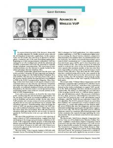
II. GAS MIXTURE OPTIMIZATION For incident charged particles, the intrinsic time resolution of a triple-GEM detector depends on two factors [3]: the time distribution on the arrival time of primary clusters on the first GEM, , and the single electron sensitivity, i.e., the probability of triggering on the signal corresponding to one ionization electron. , where is the number The former is given by is the electron drift velocity of clusters per unit length and in the ionization gap, both terms depending on the choice of gas mixture. The latter depends on GEM gains, on the transparency of GEM foils to drifting electrons and, when using fast electronics, on detector geometry (the signal amplitude is inversely proportional to induction gap thickness). The occurence of discharges in gas detectors, i.e., the breakdown of gas rigidity, is correlated with the transition from avalanche to streamer occurring when the primary avalanche ion-electron pairs [4], [5], the so called size exceeds few Raether limit. In GEM detectors, due to very small distance between the two sides of the GEM foil, streamer formation can be easily followed by a discharge. This effect can be minimized by both adding a quencher to the gas mixture, whose quantity and type are however limited by detector ageing, and optimizing the detector configuration in order to benefit from the diffusion effect which spreads the charge over more holes. The above-mentioned requirements lead us to select two new gas mixtures improving both and quenching properties: Ar/CO /CF (45/15/40) and Ar/CF /C H (65/28/7). The isobutane content was kept below the flammability limity of the gas mixture. Fig. 1 shows the drift velocity versus electric field and Fig. 2 the resolution on the arrival time of primary clusters on the first GEM, , versus electric field as calculated with Magbolz [6] and Heed [7] programs for the four gas mixtures we tested and shows that properties at low fields are better for the new ones. The number of primary clusters per incident charged particle in the 3 mm drift gap are calculated to be 15.3 for Ar/CO /CF (60/20/20), 12 for Ar/CO (70/30), 17.1 for Ar/CF /C H (65/28/7) and 17.2 for Ar/CO /CF (45/15/40).
0018-9499/04$20.00 © 2004 IEEE
2136
IEEE TRANSACTIONS ON NUCLEAR SCIENCE, VOL. 51, NO. 5, OCTOBER 2004
Fig. 1. Calculated electron drift velocity versus electric field for the four gas mixtures tested by our group.
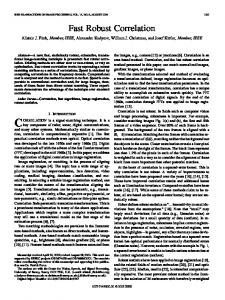
Fig. 3. Measured effective gain versus U
.
GEM foils and a large detector with 20 24 cm active area made with custom-designed CERN GEM foils. The large GEM foils were divided in six sectors to reduce the spark energy in case of a discharge event. The gap thicknesses were 3/1/2/1 mm, respectively, for the ionization, the first and the second transfer, and the induction gap. The readout board is segmented in pad of size 10 25 mm . Each pad is connected to a fast (5-ns shaping time) charge-integrating amplifier, followed by a discriminator. The noise figure of the charge amplifiers and the detector stability allow to set a discriminator level to about 2 fC. B. Gain
Fig. 2. Calculated resolution on the arrival time of the first primary cluster on the first GEM versus electric field for the four gas mixtures tested by our group.
III. DETECTOR PERFORMANCES To make a comparison of the performances of the different gas mixtures, efficiency, cluster size and discharge probability are measured as a function of gain. Results were corrected to take into account the fact that data were in general collected at different ambient temperatures and pressures. A. Prototypes Two different prototypes were tested by our group: a small detector with 10 10 cm active area made with standard CERN
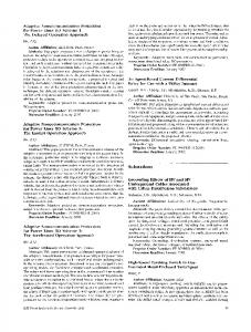
Effective gain measurements, as a function of the total voltage , were performed by means applied to the three GEMs because of a 5.9-keV X-ray tube [3]. (We always consider the gain is largely independent on how the total voltage is distributed on the three GEM foils.) Effective gain values were obtained from the ratio of pad current with high voltage on the GEM foils, to current on the first GEM, with no high voltage on the GEM foils, and are shown in Fig. 3. All the gas mix, which allow an effitures allow to reach a gain of about cient detection of minimum ionizing particles in safe working conditions. The gain was also measured on each detector pad, resulting in a gain uniformity within 10%–15% on all the active area. C. Time Performance Fig. 4 shows the efficiency in a 20-ns time window versus effective gain for minimum ionizing particles. The best rms of the time distribution obtained were 6 ns for Ar/CO /CF (60/20/20) and 4.5 ns for Ar/CF /C H (65/28/7) and Ar/CO /CF (45/15/40), to be compare favorably with 10 ns for Ar/CO (70/30). Fig. 5 shows the efficiency versus gain with two detectors in an OR configuration after discrimination, in order to reproduce
ALFONSI et al.: ADVANCES IN FAST MULTI-GEM-BASED DETECTOR OPERATION FOR HIGH-RATE CHARGED-PARTICLE TRIGGERING
Fig. 6.
2137
Measured cluster size versus effective gain.
Fig. 4. Measured single detector efficiency versus gain in a 20-ns time window.
D. Cluster Size The cluster size is defined as the number of pads per event which fired the discriminator in a region around the first triggered pad of the event and in a time window of 25 ns (time-distance between two bunch-crossings at LHC). Fig. 6 shows the cluster size for the three gas mixtures versus effective gain. As expected, the cluster size depends on signal amplitude, and since the number of primary ionization electrons is similar for the three mixures (see Section II), the pad cluster size is directly related to the effective gain. E. Discharge Probability
Fig. 5. Measured efficiency versus gain of two detectors in OR after discrimination in a 20 ns time window.
the detector configuration that will be used in the LHCb muon station 1. Therefore, the value of effective gain which corresponds to 96% efficiency in Fig. 5 is defined to be, according to LHCb requirements, the start of the operating region of the detector. This value turns out to be different from gas to gas. The end of the operating region is defined by the smallest gain value corresponding to maximum tolerable discharge probability per incident particle (see Section III-E) and the maximum tolerable pad cluster size (see Section III-D).
The measurement was performed at the M1 experimental area of PSI, Villigen (CH). The beam was quasi-continuous with 19-ns time separation between bunches, mainly composed of pions of 350-MeV/c momentum with an estimated contamination of 7% of protons. During this test, the pads were all connected together to a single high-voltage channel, similarly to the other electrodes. All electrode currents were continuously monitored. Discharge counting was performed by detecting current spikes on one of the high-voltage channels feeding the detector. Typical recharge time for the electrodes was 100 ms, therefore the detection efficiency of these discharges was estimated to be 100%. Eight high-voltage channels per detector were used. Incoming particle rate was measured from the current measured on all detector pads. Absolute calibration was obtained from a 2 2 cm scintillation counter at low beam intensity. The beam size was estimated moving the beam with respect to the scintillator in both horizontal and vertical direction and was found to have a two-dimensional gaussian shape of about 3 5 cm FWHM. The total average rate over time on the detector was estimated to be 300 MHz with an uncertainty of about 10%, well below the rate capability limit of GEM detectors [1].
2138
IEEE TRANSACTIONS ON NUCLEAR SCIENCE, VOL. 51, NO. 5, OCTOBER 2004
Fig. 7. Measured discharge probability per incident charged particle versus effective gain.
Discharge probability is defined as the ratio between the observed number of discharges and incident particle number in a given time. During the test, the three detectors under test integrated about 5000 discharges each, with stable performance. No dark current above 100 nA was observed on any electrode. Taking into account the expected average charged particle rate in the LHCb experiment, the same amount of discharges will be integrated in 10 years of running an LHCb provided that we keep the discharge . The efprobability per incident charged particle below fective gain corresponding to this value of discharge probability per incident charged particles defines the end of the working region. However, since we did not observe any degradation in detector performances, we consider this to be a conservative estimate. Measured discharge probabilities per incident particle are shown for the three gas mixtures in Fig. 7. The working for regions in terms of effective gain are for Ar/CF /C H Ar/CO /CF (60/20/20), (65/28/7) and for Ar/CO /CF (45/15/40), with gain ratios of about 1.9 for Ar/CO /CF (60/20/20), of 6 for Ar/CF /C H (65/28/7) and of 5.5 for Ar/CO /CF (45/15/40), corresponding to 36, 83, and 100 V, respectively, in . Within the working regions, the pad cluster size terms of is also well within the requirements of the experiment for the three gas mixtures. IV. AGING TESTS Three different aging tests were performed to investigate the possible detector performance losses as a function of the integrated charge. The following results were obtained by using prototypes described in Section III. A with the Ar/CO /CF (45/15/40) gas mixture: Local, large-area, and global aging test.In the first two tests gas flow was set to 200 cc/min, while in the last test we set the maximum flow that our gas system
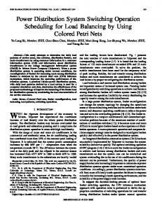
Fig. 8. Detector currents versus integrated charge for the aging tests described in the text. Dark and light grey points are the currents for detectors A and B during irradiation at 16 Gy/h. Black points are the current for detector C during irradiation at 0.5 Gy/h. Triangles are data from the local aging test. All data are corrected for ambient temperature and pressure variations.
could provide (350 cc/min). In the local test a detector area of about 1 mm was irradiated with soft (6 keV) X-rays by means of a X-ray tube. A total charge of 4 C/cm was integrated in about two weeks, which corresponds to 25 years of operation at LHCb. The large area test is the test performed at PSI to measure the discharge probability. During this test a total charge of 0.5 C/cm was integrated in about a week, corresponding to 3 years at LHCb. Finally, the global test was performed by means on a 25 kCi Co source at the ENEA-Casaccia Calliope Irradiation Facility. During this test two similar detectors (A and B) were irradiated at about 16 Gy/h and a total charge of 2 C/cm was integrated in about 35 days, which corresponds to 12.5 LHCb years. Another detector (C) was only irradiated at 0.5 Gy/h and up to a total charge of 0.14 C/cm , which corresponds to slightly less than one LHCb year. In this last test the water content of the gas mixture was continuously monitored, and was always below 1 ppm (in volume) if one excludes the first week of operation. There was however no apparent correlation between the current and the gas humidity. Results for local and global aging test are shown in Fig. 8. Large area test data are not shown on the same plot because the detector current was not continuously monitored but only measured at the beginning and at the end of the test, and from these measurements a current drop larger than 5% for a total integrated charge of 0.5 C/cm can be excluded. It is evident from Fig. 8 that no current variations are present for the local aging test, while an evident current drop was observed during the global aging test for heavily irradiated detectors (A and B). There is a small evidence, although with very low significance due to the large instrinsic fluctuations in the data, that the less irradiated detector (C) does not show the same current decrease rate as detectors A and B. This might indicate an
ALFONSI et al.: ADVANCES IN FAST MULTI-GEM-BASED DETECTOR OPERATION FOR HIGH-RATE CHARGED-PARTICLE TRIGGERING
2139
V. CONCLUSION We discussed the performance of 10 10 cm and 20 24 cm active area triple-GEM detectors with CF -based gas mixtures. Two of these, Ar/CF /C H (65/28/7) and Ar/CO /CF (45/15/40), satisfy the LHCb requirements in terms of time resolution, pad cluster size and discharge probability per incident particle corresponding to the harsh environment of the inner part of the first muon station. An operating region of more than 80 V for the triple-GEM detector with these two gas mixtures was found. Preliminary results on aging test were also reported. The detector current drop versus integrated charge observed during heavy global irradiation was not observed during local and large-area aging tests. This seems to suggest a possible problem with the gas flow. Investigation on these discrepancies are in progress. A new global aging test is foreseen during 2004. Fig. 9. Close view of a GEM foil near a hole taken with an optical microscope.The GEM foil was used in a detector that was aged in a CF -based gas mixture.
effect related to the gas flow. It is indeed the case that for heavily irradiated detectors the gas flow was not increased proportionally to the irradiation rate, due to limitations in the gas system. The reason of the detector current drop is very likely due to the etching of the copper and Kapton near the GEM holes by fluorine. The modification of the electrode geometry decreases the electric field intensity inside the holes, resulting in a smaller gain and subsequently in a decrease of the detector current during the irradiation. GEM foil pictures taken at the optical microscope (see Fig. 9) tend to support this interpretation, although more extensive physical and chemical analysis are still underway. Investigation on the discrepancies between different aging test is in progress. A new global aging test is foreseen during 2004.
REFERENCES [1] F. Sauli, “GEM: A new concept for electron amplification in gas detectors,” Nucl. Instrum. Methods, vol. A386, pp. 531–534, 1997. [2] A. Buzulutskov, A. Breskin, R. Chechik, G. Garty, F. Sauli, and L. Shekhtman, “The GEM photomultiplier operated with noble gas mixtures,” Nucl. Instrum. Methods, vol. A443, pp. 164–180, 2000. [3] G. Bencivenni et al., “A triple GEM detector with pad readout for high rate charged particle triggering,” Nucl. Instrum. Methods, vol. A488, pp. 493–502, 2002. [4] S. Bachmann et al., “Performance of GEM detectors in high intensity particle beams,” Nucl. Instrum. Methods, vol. A470, pp. 548–561, 2001. [5] S. Bachmann et al., “Discharge studies and prevention in the gas electron multiplier,” Nucl. Instrum. Methods, vol. A479, pp. 294–308, 2002. [6] S. Biagi. Magboltz Program. CERN Program Library. [Online]. Available: http://consult.cern.ch/writeup/magboltz [7] I. Smirnov. HEED Program. CERN Program Library. [Online]. Available: http://consult.cern.ch/writeup/heed