H. Bijl. Technische Universiteit Delft, promotor. Dr. R.P. Dwight. Technische ...... The blue line represents the plunging mode and the green line the pitching.
A EROEL ASTIC L IMIT-C YCLE O SCILL ATIONS RESULTING FROM
A ERODYNAMIC N ON -L INEARITIES
A EROEL ASTIC L IMIT-C YCLE O SCILL ATIONS RESULTING FROM
A ERODYNAMIC N ON -L INEARITIES
Proefschrift ter verkrijging van de graad van doctor aan de Technische Universiteit Delft, op gezag van de Rector Magnificus prof. ir. K.C.A.M. Luyben, voorzitter van het College voor Promoties, in het openbaar te verdedigen op woensdag 12 april 2017 om 10:00 uur
door
Anna Catharina Leonarda Maria VAN R OOIJ ingenieur luchtvaart- en ruimtevaarttechniek, geboren te Berkel-Enschot.
Dit proefschrift is goedgekeurd door de promotor: Prof. dr. ir. drs. H. Bijl copromotor: Dr. R.P. Dwight Samenstelling promotiecommissie: Rector Magnificus Prof. dr. ir. drs. H. Bijl Dr. R.P. Dwight
voorzitter Technische Universiteit Delft, promotor Technische Universiteit Delft, copromotor
Onafhankelijke leden: Prof. dr. K.J. Badcock Prof. dr. G. Dimitriadis Prof. dr. S. Hickel Dr. D.E. Raveh Prof. dr. L. Tichy Prof. dr. F. Scarano
University of Liverpool, Verenigd Koninkrijk Université de Liège, België Technische Universiteit Delft Technion, Israël Deutsches Zentrum für Luft- und Raumfahrt, Duitsland Technische Universiteit Delft, reservelid
This research was supported by the Institute of Aeroelasiticy of the German Aerospace Center (DLR).
Keywords:
Aeroelasticity, limit-cycle oscillations, unsteady aerodynamics, bifurcation behaviour, structural parameter variations
Printed by:
Sieca Repro Delft
Front & Back:
A.C.L.M. van Rooij
Copyright © 2017 by A.C.L.M. van Rooij ISBN 978-94-6186-794-0 An electronic version of this dissertation is available at http://repository.tudelft.nl/.
C ONTENTS Summary
ix
Samenvatting
xiii
Preface
xvii
1 Introduction 1.1 Motivation of this thesis. . . . . . . . . . . . . . . 1.2 Limit-cycle oscillations . . . . . . . . . . . . . . . 1.3 Previous investigations on limit-cycle oscillations . 1.3.1 Computational methods . . . . . . . . . . . 1.3.2 Limit-cycle oscillation bifurcation behaviour 1.3.3 Conclusions and open questions. . . . . . . 1.4 Objectives. . . . . . . . . . . . . . . . . . . . . . 1.5 Outline of the thesis . . . . . . . . . . . . . . . . . References . . . . . . . . . . . . . . . . . . . . . . . .
. . . . . . . . .
. . . . . . . . .
. . . . . . . . .
. . . . . . . . .
. . . . . . . . .
. . . . . . . . .
. . . . . . . . .
. . . . . . . . .
. . . . . . . . .
. . . . . . . . .
. . . . . . . . .
1 . 2 . 3 . 5 . 5 . 6 . 8 . 10 . 11 . 11
2 Aeroelastic problem description and solution strategies 2.1 Introduction . . . . . . . . . . . . . . . . . . . . 2.2 Aeroelastic problem description . . . . . . . . . . 2.2.1 NLR7301 airfoil . . . . . . . . . . . . . . . 2.2.2 Structural model . . . . . . . . . . . . . . . 2.2.3 Fluid model . . . . . . . . . . . . . . . . . 2.3 Fluid-structure coupling in the time domain . . . . 2.4 Linear flutter in the frequency domain . . . . . . . 2.4.1 Conventional p-k method . . . . . . . . . . 2.4.2 Frequency response functions . . . . . . . . 2.4.3 Linear flutter . . . . . . . . . . . . . . . . . 2.5 Limit-cycle oscillations in the frequency domain . . 2.5.1 Amplitude-dependent p-k method (ADePK) . 2.5.2 Harmonic forced motion oscillations . . . . 2.5.3 Limit-cycle oscillations . . . . . . . . . . . 2.5.4 Sampling and interpolation techniques . . . 2.5.5 The ADePK method in perspective . . . . . . References . . . . . . . . . . . . . . . . . . . . . . . .
. . . . . . . . . . . . . . . . .
. . . . . . . . . . . . . . . . .
. . . . . . . . . . . . . . . . .
. . . . . . . . . . . . . . . . .
. . . . . . . . . . . . . . . . .
. . . . . . . . . . . . . . . . .
. . . . . . . . . . . . . . . . .
. . . . . . . . . . . . . . . . .
. . . . . . . . . . . . . . . . .
. . . . . . . . . . . . . . . . .
. . . . . . . . . . . . . . . . .
. . . . . . . . . . . . . . . . .
17 17 17 19 20 21 28 29 29 31 33 33 34 36 39 41 41 43
3 Energy budget analysis of limit-cycle oscillations 3.1 Introduction . . . . . . . . . . . . . . . . . . . . . . . . . . . . . . . . 3.2 Computational methods . . . . . . . . . . . . . . . . . . . . . . . . . . 3.2.1 CFD code and set-up. . . . . . . . . . . . . . . . . . . . . . . . .
49 49 50 50
v
vi
C ONTENTS 3.2.2 Structural model . . . . . . . . . . . . . . 3.2.3 Fluid-structure interaction . . . . . . . . . 3.2.4 Forced motion oscillations . . . . . . . . . 3.3 Results and discussion . . . . . . . . . . . . . . 3.3.1 Van der Pol-oscillator . . . . . . . . . . . 3.3.2 Fluid-structure interaction . . . . . . . . . 3.3.3 Single harmonic forced motion oscillations 3.3.4 Non-linear aerodynamic power defect . . . 3.4 Conclusions. . . . . . . . . . . . . . . . . . . . References . . . . . . . . . . . . . . . . . . . . . . .
. . . . . . . . . .
. . . . . . . . . .
. . . . . . . . . .
. . . . . . . . . .
. . . . . . . . . .
. . . . . . . . . .
. . . . . . . . . .
. . . . . . . . . .
. . . . . . . . . .
. . . . . . . . . .
. . . . . . . . . .
51 51 52 53 54 58 62 64 69 70
4 Verification and validation of the amplitude-dependent p-k method 4.1 Introduction . . . . . . . . . . . . . . . . . . . . . . . . . . . 4.2 Computational methods and set-up . . . . . . . . . . . . . . . 4.2.1 CFD code and set-up. . . . . . . . . . . . . . . . . . . . 4.2.2 Two DoF airfoil system . . . . . . . . . . . . . . . . . . . 4.2.3 Fluid-structure coupling . . . . . . . . . . . . . . . . . . 4.2.4 Conventional p-k method . . . . . . . . . . . . . . . . . 4.2.5 Amplitude-dependent p-k method ADePK. . . . . . . . . 4.3 Results and discussion . . . . . . . . . . . . . . . . . . . . . . 4.3.1 Van der Pol-oscillator . . . . . . . . . . . . . . . . . . . 4.3.2 Two DoF airfoil system . . . . . . . . . . . . . . . . . . . 4.3.3 Structural parameter variation . . . . . . . . . . . . . . . 4.4 Conclusions. . . . . . . . . . . . . . . . . . . . . . . . . . . . References . . . . . . . . . . . . . . . . . . . . . . . . . . . . . . .
. . . . . . . . . . . . .
. . . . . . . . . . . . .
. . . . . . . . . . . . .
. . . . . . . . . . . . .
. . . . . . . . . . . . .
73 73 75 75 75 75 76 76 77 77 84 91 94 94
5 Bifurcation behaviour of limit-cycle oscillation solutions 5.1 Introduction . . . . . . . . . . . . . . . . . . . . . . . 5.2 Sources of aerodynamic non-linearity . . . . . . . . . . 5.2.1 Transonic inviscid flow. . . . . . . . . . . . . . . 5.2.2 Transonic flow with trailing-edge separation . . . . 5.2.3 Subsonic flow with trailing-edge separation . . . . 5.2.4 Subsonic flow with free boundary-layer transition . 5.2.5 Conclusions . . . . . . . . . . . . . . . . . . . . 5.3 Mach number variation in inviscid flow. . . . . . . . . . 5.3.1 Flutter behaviour . . . . . . . . . . . . . . . . . 5.3.2 LCO bifurcation behaviour . . . . . . . . . . . . . 5.3.3 Conclusions . . . . . . . . . . . . . . . . . . . . 5.4 Structural parameter variation . . . . . . . . . . . . . . 5.4.1 Structural frequency ratio . . . . . . . . . . . . . 5.4.2 Mass ratio . . . . . . . . . . . . . . . . . . . . . 5.4.3 Structural damping . . . . . . . . . . . . . . . . 5.4.4 Elastic axis location . . . . . . . . . . . . . . . . 5.4.5 Conclusions . . . . . . . . . . . . . . . . . . . .
. . . . . . . . . . . . . . . . .
. . . . . . . . . . . . . . . . .
. . . . . . . . . . . . . . . . .
. . . . . . . . . . . . . . . . .
. . . . . . . . . . . . . . . . .
97 97 98 99 100 102 105 107 110 110 112 116 116 117 126 129 131 133
. . . . . . . . . . . . . . . . .
. . . . . . . . . .
. . . . . . . . . . . . . . . . .
. . . . . . . . . .
. . . . . . . . . . . . . . . . .
. . . . . . . . . . . . . . . . .
C ONTENTS
vii
5.5 Response surface analysis. . . . . . . 5.5.1 One DoF van der Pol-oscillator. 5.5.2 Two DoF van der Pol-oscillator. 5.5.3 Two DoF airfoil system . . . . . 5.5.4 Conclusions . . . . . . . . . . 5.6 Conclusions. . . . . . . . . . . . . . References . . . . . . . . . . . . . . . . .
. . . . . . .
. . . . . . .
. . . . . . .
. . . . . . .
. . . . . . .
. . . . . . .
. . . . . . .
. . . . . . .
. . . . . . .
. . . . . . .
. . . . . . .
. . . . . . .
. . . . . . .
. . . . . . .
. . . . . . .
. . . . . . .
. . . . . . .
. . . . . . .
. . . . . . .
135 135 137 142 151 152 154
6 Conclusions and outlook 6.1 Energy budget analysis . . . . . . . . . . . . . . . . . . . . . . . 6.2 Verification and validation of the amplitude-dependent p-k method 6.3 Bifurcation behaviour of limit-cycle oscillation solutions . . . . . . 6.4 Outlook . . . . . . . . . . . . . . . . . . . . . . . . . . . . . . .
. . . .
. . . .
. . . .
. . . .
157 157 158 159 160
A Experimental validation 161 References . . . . . . . . . . . . . . . . . . . . . . . . . . . . . . . . . . . . 162 B Mesh- and time step convergence B.1 Mesh . . . . . . . . . . . . . B.1.1 Euler simulations . . . B.1.2 RANS simulations . . . B.2 Time step . . . . . . . . . . . B.2.1 Euler simulations . . . B.2.2 RANS simulations . . .
. . . . . .
. . . . . .
. . . . . .
. . . . . .
. . . . . .
. . . . . .
. . . . . .
. . . . . .
. . . . . .
. . . . . .
. . . . . .
. . . . . .
. . . . . .
. . . . . .
. . . . . .
. . . . . .
. . . . . .
. . . . . .
. . . . . .
. . . . . .
. . . . . .
. . . . . .
. . . . . .
163 163 163 165 169 169 170
C Interpolation methods C.1 Polynomial interpolation . C.2 Cubic spline interpolation C.3 Linear interpolation. . . . References . . . . . . . . . . .
. . . .
. . . .
. . . .
. . . .
. . . .
. . . .
. . . .
. . . .
. . . .
. . . .
. . . .
. . . .
. . . .
. . . .
. . . .
. . . .
. . . .
. . . .
. . . .
. . . .
. . . .
. . . .
. . . .
175 175 176 178 178
D Additional Results of the amplitude-dependent p-k method D.1 Structural parameter variation . . . . . . . . . . . . . D.1.1 Mass ratio . . . . . . . . . . . . . . . . . . . . D.1.2 Structural damping . . . . . . . . . . . . . . . D.1.3 Elastic axis location . . . . . . . . . . . . . . . D.2 Response surface analysis. . . . . . . . . . . . . . . .
. . . . .
. . . . .
. . . . .
. . . . .
. . . . .
. . . . .
. . . . .
. . . . .
. . . . .
. . . . .
179 179 179 186 190 194
. . . .
. . . .
Curriculum Vitæ
197
List of Publications
199
S UMMARY Aeroelasticity is the discipline that studies the interaction between structures and the fluid flow around them. Flexible structures can easily be deformed by the fluid flow. The resulting aerodynamic forces in turn affect the structural deformation. Typical aeroelastic problems include a gust encounter and flutter. A disturbance in the air, for example turbulence, might cause oscillations of the aircraft’s wing. At certain air speeds the amplitude of these oscillations grows unbounded, i.e. flutter occurs. The flutter boundary, beyond which the oscillation amplitude grows unbounded, should never be surpassed in flight. In contrast, during so-called limit-cycle oscillations (LCOs) the oscillation amplitude stays constant. Limit-cycle oscillations are caused by non-linearities in either the structure or the fluid flow around the aeroelastic system or by a combination of both. Structural non-linearities can be for example freeplay or non-linear damping. Aerodynamic non-linearities include shock wave dynamics, boundary-layer separation and boundary-layer transition. This thesis only considers aerodynamic non-linearities. Flutter onset is normally computed using a linearised method. However, since a certain minimum disturbance level is necessary for flutter to occur, flutter is, in reality, always non-linear. This means that a linearised method might not predict flutter onset correctly. Hence, it might be possible that non-linear flutter, i.e. an LCO, already occurs below the flutter boundary predicted from linearised theory. Whether limit-cycle oscillations caused by aerodynamic non-linearities can occur below the linear flutter speed has not yet been investigated systematically. Therefore, the main research question of this thesis is whether LCOs caused by aerodynamic non-linearities can already occur below the flutter boundary predicted from linearised theory. Theoretically, there are two types of LCOs that might exist when considering aerodynamic non-linearities only. LCOs that occur beyond the flutter boundary are so-called benign LCOs. These benign LCOs are stable. In other words, when the system is disturbed, it will return to its LCO state. In contrast, so-called detrimental LCOs might occur already below the flutter boundary. They are stable and they are accompanied by an unstable LCO of smaller amplitude that occurs at the same freestream velocity. The amplitude of this unstable LCO marks the boundary between two stable states; a stable LCO and a steady state (without oscillations). When a detrimental LCO would occur in reality, the linearised flutter onset computation would not be correct, since non-linear flutter, i.e. a stable LCO, would exist below the flutter boundary. The variation of the LCO’s amplitude with for example the freestream velocity or the dynamic pressure is mathematically called the bifurcation behaviour. Benign LCOs cause so-called supercritical bifurcations and detrimental LCOs cause so-called subcritical bifurcations. In this thesis limit-cycle oscillations of a two degree-of-freedom airfoil system caused by aerodynamic non-linearities were studied. In order to do so fully coupled fluid-structure interaction (FSI) simulations as well as forced motion oscillation simulations were performed. The supercritical NLR7301 airfoil has been used for all analyses in this thesis. ix
x
S UMMARY
The degrees of freedom of the airfoil are pitch and plunge. First, the energy budget of the LCOs was analysed. The mean power components computed from FSI simulations showed that the mean total power (sum of the mean power of the aerodynamic lift, aerodynamic moment and structural damping) is zero at the LCO amplitude, as expected. Furthermore, a defect in the mean power of the aerodynamic lift was found to be responsible for the amplitude limitation. This defect originates from the impact of small variations of the phase of the lift with oscillation amplitude. The small variations of the magnitude and phase of the aerodynamic moment do not have the same impact on the mean aerodynamic power (sum of the mean power of the lift and mean power of the moment) as those of the lift. Therefore, the defect in the mean power of the moment is much smaller than that in the mean power of the lift. Due to the complicated flow behaviour, no local features were found to be responsible for the defect in the mean power of the lift. To study the bifurcation behaviour of the LCOs of the two degree-of-freedom airfoil system, an extension to the well-known p-k method used in classical linear flutter analysis has been developed in this thesis. This method is called the amplitude-dependent p-k method (ADePK), since it takes into account the amplitude of the (forced) motion (in contrast to the standard p-k method). ADePK solves the equations of motion in the frequency domain. In order to do so, a so-called response surface is first set up from forced motion oscillation simulations at several amplitudes, frequencies and complexvalued amplitude ratios between the two degrees of freedom. The response of the lift and moment to these forced motion oscillation simulations is then transferred into the frequency domain via a Fourier transformation. During the iterations of ADePK the first harmonic of the aerodynamic force and moment is obtained from interpolation on the response surface. The LCO amplitude and mode shape are found iteratively from ADePK. In order to verify ADePK the van der Pol-oscillator has been used. After verification, the method has been validated against time domain results for the two degreeof-freedom airfoil system. The bifurcation behaviour of the LCO amplitude and mode shape obtained from ADePK showed good agreement with the results of the FSI simulations in the time domain. After validation of ADePK, it has been used for systematic studies of the bifurcation behaviour of the LCO amplitude of the two degree-of-freedom airfoil system. Several response surfaces were built in order to study various aerodynamic non-linearities. A bifurcation behaviour analysis using these response surfaces showed that the strongest non-linearity occurs in transonic flow with trailing-edge separation. For the other test cases, transonic inviscid flow, subsonic flow with trailing-edge separation and subsonic flow with free boundary-layer transition, limit-cycle oscillations only occurred very close to the flutter boundary, hence the non-linearity was observed to be relatively weak. In case of transonic inviscid flow multiple nested LCOs (of different amplitude) occurred at one freestream velocity, i.e. a detrimental LCO occurred. To study the effect of LCOs close to the flutter boundary, the Mach number was varied in inviscid flow. The linear flutter boundary, shows, as expected, a so-called transonic dip, i.e. a minimum in the flutter boundary at transonic flow speeds. Contours of constant LCO amplitude showed that at subsonic Mach numbers the LCO amplitude increases much faster than at transonic speeds. Furthermore, these contours showed
S UMMARY
xi
that the transonic dip could be significantly less deep when a certain LCO amplitude is considered. A variation of the structural frequency ratio of the two degree-of-freedom airfoil system showed a significant influence on the bifurcation behaviour for all four aerodynamic non-linearities. In subsonic flow with trailing-edge separation, increasing the structural frequency ratio resulted in detrimental LCOs or unstable LCOs only (up to an amplitude of 5◦ ). For the viscous transonic flow test case, the bifurcation behaviour was supercritical at all structural frequency ratios studied in this thesis, except for the largest structural frequency ratio at which only unstable LCOS (up to an amplitude of 5◦ ) were obtained. In inviscid transonic flow, both detrimental and benign LCOs were observed as well. In subsonic flow with free boundary-layer transition slightly subcritical bifurcations and supercritical bifurcations of the LCO solutions were observed when the structural frequency ratio was varied. Furthermore, for all aerodynamic non-linearities, the LCO mode shape changes from plunge dominated to pitch dominated when the structural frequency ratio increases, as expected. The non-dimensional mass ratio was also changed for all test cases, however, no significant changes in the bifurcation behaviour were observed, unless the non-linearity was already very weak. In that case a change from a benign to a detrimental LCO is possible when the mass ratio is changed. However, the strength of the non-linearity is influenced by a mass ratio change. The same holds for the addition of structural damping to the two degree-of-freedom system. For all sources of aerodynamic non-linearity, variation of the elastic axis location was found to significantly influence the strength of the non-linearity and in case of a weak nonlinearity, the bifurcation type can easily change from supercritical to subcritical (or the other way around) when the elastic axis is moved. It was observed that a subcritical bifurcation of the LCO solution occurs, in viscous transonic flow, when the elastic axis is moved aft at the second largest structural frequency ratio tested. The response surface necessary to apply the ADePK method has been studied to investigate whether it revealed any clues on the bifurcation type. Using one-at-a-time linearised aerodynamic forces it was found that, at the nominal structural parameter values, the phase of the lift has the largest influence on the bifurcation behaviour. Keeping the phase of the lift at its linearised value and performing a bifurcation behaviour computation with ADePK resulted in a completely different bifurcation behaviour than when the amplitude-dependence of the phase of the lift is taken into account (for all aerodynamic non-linearities). Therefore, the phase of the lift-slices of the response surface versus amplitude (at the flutter- and 5◦ -LCO amplitude mode shapes) were studied. A comparison of the sine of these slices (i.e. the sine of the phase of the lift versus the oscillation amplitude) to the bifurcation diagram revealed a very similar shape. However, for other structural frequency ratios then the nominal one, the shape of the sine of the lift and that of bifurcation diagram were not always similar. Hence, further investigations are needed to clarify why for other structural parameters these two curves do no longer exhibit a similar shape or to identify a parameter that has the same shape as the bifurcation diagram for all structural parameter values. Using the flutter mode shape to compute the phase of the lift from forced motion oscillation simulations, the local features responsible for the behaviour of the phase of the lift and hence for the LCO behaviour have been studied. For both transonic test
xii
S UMMARY
cases, the shock motion on the lower surface of the airfoil was found to be responsible for the changes in the phase of the lift. In this thesis fundamental investigations into the bifurcation behaviour of a twodegree-of-freedom airfoil system with aerodynamic non-linearities have been performed. A first step has been made in identifying the effect of various structural parameter changes, in identifying the relation between the aerodynamic forces and the LCO bifurcation behaviour and in identifying possible ways to predict the LCO bifurcation behaviour from the flutter onset behaviour. These investigations with ADePK serve as the basis for larger degree-of-freedom systems.
S AMENVATTING Aero-elasticiteit is de discipline die de interactie tussen constructies en de stroming om deze constructies bestudeert. Flexibele constructies kunnen gemakkelijk gedeformeerd worden door de stroming. De resulterende aerodynamische krachten beïnvloeden dan op hun beurt de deformatie van de constructie. Typische aero-elastische problemen zijn bijvoorbeeld een windvlaag-confrontatie en fladderen. Storingen in de lucht, zoals turbulentie, kunnen oscillaties van de vleugel van het vliegtuig veroorzaken. Op bepaalde luchtsnelheden kan de amplitude van deze oscillaties ongelimiteerd groeien, dan treedt “fladderen” op. De fladdergrens, boven welke de oscillatie amplitude ongelimiteerd groeit, mag tijdens een vlucht nooit worden overschreden. In tegenstelling tot fladderen blijft bij zogenaamde limietcycli de oscillatie amplitude constant. Limietcykli worden veroorzaakt door niet-lineariteiten in de constructie of in de stroming om de aero-elastische constructie of door een combinatie van beide. Niet-lineariteiten in de constructie zijn bijvoorbeeld “freeplay” of niet-lineaire demping. Aerodynamische nietlineariteiten zijn de dynamica van schokgolven, grenslaag loslating en grenslaag transitie. Dit proefschrift neemt alleen aerodynamische niet-lineariteiten in beschouwing. Het optreden van fladderen wordt normaal gesproken berekend door middel van linearisatie. Echter, fladderen is in werkelijkheid altijd niet-lineair, omdat een bepaald storingsniveau nodig is voordat fladderen optreedt. Dit betekent dat een gelineariseerde methode het optreden van fladderen mogelijk niet correct zal voorspellen. Daarom zou het mogelijk kunnen zijn dat niet-lineair fladderen, m.a.w. een limietcyclus, al onder de, door gelineariseerde theorie voorspelde, fladdergrens optreedt. Of limietcycli veroorzaakt door aerodynamische niet-lineariteiten al onder de lineaire fladder snelheid kunnen optreden is nog niet systematisch onderzocht. Daarom is de hoofdonderzoeksvraag van deze dissertatie of limietcycli die veroorzaakt worden door aerodynamische niet-lineariteiten al onder de, door gelineariseerde theorie voorspelde, fladdergrens op kunnen treden. Theoretisch zijn er twee typen limietcycli die zouden kunnen optreden als alleen aerodynamische niet-lineariteiten worden beschouwd. Limietcykli die boven de fladdergrens optreden zijn de zogenaamde goedaardige limietcycli. Deze goedaardige limietcycli zijn stabiel. Met andere woorden, als het systeem wordt verstoord, zal het naar zijn limietcyclus-toestand terugkeren. In tegenstelling tot goedaardige limietcycli, zouden kwaadaardige limietcycli al onder de fladdegrens kunnen optreden. Zij zijn stabiel en worden vergezelt door een instabiele limietcyclus met een kleinere amplitude die op dezelfde luchtsnelheid optreedt. De amplitude van deze instabiele limitcyclus markeert de grens tussen twee stabiele toestanden; een stabiele limietcyclus en een stationaire toestand (zonder oscillaties). Als een kwaadaardige limietcyclus in werkelijkheid zou optreden, dan zou de de linearisatie om het optreden van fladderen te voorspellen eigenlijk niet correct zijn, omdat niet-lineair fladderen, d.w.z. een stabiele limietcyclus, al onder de fladdergrens zou optreden. De variatie van de limietcyclus amplitude met bijvoorxiii
xiv
S AMENVATTING
beeld de luchtsnelheid of de dynamische druk wordt bifurcatie gedrag genoemd in de wiskunde. Goedaardige limietcycli veroorzaken zogenaamde superkritische bifurcaties en kwaadaardige limietcycli veroorzaken zogenaamde subkritische bifurcaties. In dit proefschrift worden limietcycli van een twee vrijheidsgraad vleugelprofiel systeem veroorzaakt door aerodynamische niet-lineariteiten bestudeerd. Om dat te doen worden zowel fluïdum-constructie interactie simulaties als simulaties waar een oscilleerende beweging wordt gesimuleerd, uitgevoerd. Het superkritische NLR7301 vleugelprofiel is gebruikt voor alle analyses in dit proefschrift. Het vleugelprofiel heeft als vrijheidsgraden stampen en dompen. Als eerste wordt de energiehuishouding van de limietcycli bestudeerd. De gemiddelde vermogenscomponenten, berekent door middel van de fluïdum-constructie interactie simulaties, toonden aan dat het gemiddelde totale vermogen (som van het gemiddelde vermogen van de aerodynamische liftkracht, het aerodynamische moment en de structurele constructie), zoals verwacht, nul is op de limietcyclus amplitude. Een defect in het gemiddelde vermogen van de liftkracht veroorzaakt deze begrenzing van de amplitude. Dit defect komt voort uit de impact van kleine variaties in de fase van de liftkracht die optreden zodra de oscillatie amplitude verandert. De kleine variaties in de amplitude en de fase van het aerodynamische moment hebben niet dezelfde impact op het gemiddelde aerodynamische vermogen (som van het gemiddelde vermogen van de liftkracht en van het moment) als die van de liftkracht. Daarom is het defect in het gemiddelde vermogen van het moment veel kleiner dan dat in het gemiddelde vermogen van de lift. Door het gecompliceerde stromingsgedrag was het niet mogelijk om lokale fenomenen te vinden die verantwoordelijk zijn voor het defect in het vermogen van de liftkracht. Om het bifurcatie gedrag van limietcycli van een twee vrijheidsgraad vleugelprofiel systeem te bestuderen is er een uitbreiding van de gerenommeerde p-k methode, die wordt gebruikt in een lineaire fladder analyse, ontwikkeld in dit proefschrift. Deze nieuwe methode wordt de amplitude-afhankelijke p-k methode (ADePK) genoemd, omdat rekening gehouden wordt met de amplitude van de (geforceerde) beweging (in tegenstelling tot de standaard p-k methode). De ADePK methode lost de bewegingvergelijkingen in het frequentie-bereik op. Om dat te doen, moet eerst een zogenaamd response oppervlak gegenereerd worden uit de resultaten van simulaties van geforceerde harmonische bewegingen met verschillende amplitudes, frequenties en complex-waardige amplitude verhouding tussen de twee vrijheidsgraden. De response van de liftkracht en het moment op deze geforceerde bewegingen wordt dan in het frequentie-bereik getransformeerd via een Fourier transformatie. Tijdens de iteraties van ADePK wordt de eerste harmonische component van de aerodynamische kracht en die van het moment berekend via interpolatie op het response oppervlak. De limietcyclus amplitude en trilvorm kunnen dan iteratief worden gevonden in de ADePK methode. De van der Poloscillator is gebruikt om de ADePK methode te verifiëren. Na deze verificatie is de methode gevalideerd met tijdsbereik resultaten voor het twee vrijheidsgraad vleugelprofiel systeem. Het bifurcatie gedrag van de limietcyclus amplitude en de limietcyclus trilvorm berekend met ADePK komt goed overeen met de resultaten van fluïdum-constructie interactie simulaties in het tijdsbereik. Nadat ADePK gevalideerd is, is de methode gebruikt voor systematische studies van
S AMENVATTING
xv
het bifurcatie gedrag van de limietcyclus amplitude van het twee vrijheidsgraad vleugelprofiel systeem. Er zijn verschillende response oppervlakken geconstrueerd om verschillende aerodynamische niet-lineariteiten te kunnen bestuderen. Een analyse van het bifurcatie gedrag, gebruikmakende van deze response oppervlakken, toonde aan dat de sterkste niet-lineariteit optreedt in een transsonische stroming met achterkantloslating. Voor de andere testgevallen, transsonische invisceuze stroming, subsonische stroming met achterkant-loslating en subsonische stroming met vrije grenslaagtransitie, traden limietcycli alleen heel dichtbij de fladdergrens op. De niet-lineariteit is daarom relatief zwak in deze testgevallen. In transsonische invisceuze stroming treden op één luchtstroomsnelheid meerdere limietcycli (van verschillende amplitude) tegelijk op, dat willen zeggen, er treden kwaadaardige limietcycli op. Om het effect van limietcycli dichtbij de fladdergrens te bestuderen, is het Machgetal gevarieërd. De lineaire fladdergrens laat, zoals verwacht, een zogenaamde “transsonische dip” zien, dat wil zeggen, een minimum in de fladdergrens op transsonische luchtsnelheden. Het berekenen van contouren van constante limietcyclus amplitude toont aan dat de limietcyclus amplitude bij subsonische Machgetallen veel sneller toeneemt dan bij transsonische Machgetallen. Verder lieten deze contouren zien dat, als limietcycli van een bepaalde amplitude beschouwd worden, het transsonische minimum in de fladdergrens significant minder diep kan zijn. Een variatie van de verhouding van de structurele eigenfrequenties van het twee vrijheidsgraad vleugelprofiel systeem laat een significante invloed op het bifurcatie gedrag zien voor alle vier de aerodynamische niet-lineariteiten. Het verhogen van de verhouding van structurele eigenfrequenties zorgt in subsonische stroming met achterkantloslating voor kwaadaardige limietcycli of alleen instabiele limietcycli (tot een amplitude van 5◦ ). Voor het visceuze transsonische testgeval treedt superkritisch bifurcatie gedrag op voor alle verhoudingen van de structurele eigenfrequenties die onderzocht zijn in deze dissertatie, behalve voor de grootste verhouding, voor deze verhouding treden alleen instabiele limietcycli op (tot een amplitude van 5◦ ). In invisceuze transsonische stroming treden ook zowel kwaadaardige en goedaardige limietcycli op. In subsonische stroming met vrije grenslaagtransitie treden minieme subkritische bifurcaties en superkritische bifurcaties van de limietcyclus oplossingen op als de verhouding van structurele eigenfrequenties gevarieërd wordt. Verder verandert de trilvorm, zoals verwacht, voor alle aerodynamische niet-lineariteiten van dompen-gedomineerd naar stampen-gedomineerd als de verhouding van structurele eigenfrequenties wordt vergroot. De dimensieloze massaverhouding is ook gevarieërd voor alle testgevallen. Dit resulteert echter niet in significante veranderingen in het bifurcatie gedrag, behalve als de niet-lineariteit al heel zwak was. In dat geval kan een limietcyclus van goedaardig naar kwaadaardig veranderen als de massaverhouding wordt veranderd. Echter, de sterkte van de niet-lineariteit wordt beïnvloed door een verandering van de massaverhouding. Hetzelfde geldt voor het toevoegen van structurele demping aan het twee vrijheidsgraad systeem. De variatie van de locatie van de elastische as heeft voor alle aerodynamische niet-lineariteiten een significante invloed op het bifurcatie gedrag en in als de niet-lineariteit zwak is, kan het bifurcatie gedrag gemakkelijk veranderen van superkritisch naar subkritisch (of andersom) als de elastische as wordt verplaatst. Voor de op een na grootste verhouding van structurele eigenfrequenties onderzocht in deze dis-
xvi
S AMENVATTING
sertatie, treedt, in visceuze transsonsiche stroming, een subkritische bifurcatie van de limietcyclus oplossing op wanneer de elastische as naar achter worden verplaatst. Het response oppervlak dat nodig is om berekeningen te kunnen doen met ADePK is bestudeerd om te onderzoeken of het aanwijzingen over het bifurcatie gedrag bevat. Door middel van het een-voor-een lineariseren van de aerodynamische krachten, is vastgesteld dat, op de nominale structurele parameterwaardes, de fase van de liftkracht de grootste invloed op het bifurcatie gedrag heeft. Als de fase van de liftkracht constant gehouden wordt op zijn gelineariseerde waarde, resulteert een compleet ander bifurcatie gedrag dan wanneer er rekening gehouden wordt met de amplitude-afhankelijkheid van de fase van de liftkracht (voor alle aerodynamische niet-lineariteiten). Daarom zijn doorsnedes van het response oppervlak waarop de fase van de liftkracht versus de limietcyclus amplitude (op de fladder- and de 5◦ -limietcyclus-trilvorm) te zien is, bestudeerd. Uit een vergelijking van de sinus van deze doorsnedes (d.w.z. de sinus van de liftkracht versus de oscillatie amplitude) met het bifurcatie diagram blijkt dat de vorm van deze twee grafieken ongeveer hetzelfde is. Echter, voor andere verhoudingen van de structurele eigenfrequenties dan de nominale verhouding, zijn de vorm van de sinus van de liftkracht en die van het bifurcatie diagram niet altijd ongeveer hetzelfde. Daarom is verder onderzoek nodig om uit te vinden waarom deze twee curves voor andere structurele parameters niet meerdere ongeveer dezelfde vorm hebben of om een parameter te identificeren die voor alle structurele parameterwaardes dezelfde vorm heeft als het bifurcatie diagram. De fase van de liftkracht is berekend met stromingssimulaties met een geforceerde harmonische beweging op de fladder trilvorm om lokale fenomenen verantwoordelijk voor het gedrag van de fase van de liftkracht, en dus ook voor het bifurcatie gedrag, te vinden. De schokgolf beweging op de onderkant van het vleugelprofiel wordt verantwoordelijk gehouden voor de veranderingen in de fase van de liftkracht voor de twee transsonische testgevallen. In dit proefschrift zijn fundamentele analyses gedaan die het bifurcatie gedrag van een twee vrijheidsgraad vleugelprofiel systeem met aerodynamische niet-lineariteiten onderzoeken. Een eerste stap is gezet in het identificeren van het effect van verschillende structurele parameter variaties, in het identificeren van de relatie tussen de aerodynamische krachten en het bifurcatie gedrag en in het identificeren van manieren om het limietcyclus bifurcatie gedrag te voorspellen met behulp van het lineaire fladder gedrag. Deze studies met de ADePK methode vormen de basis voor onderzoeken naar systemen met meer vrijheidsgraden.
P REFACE The research presented in this thesis has been conducted at the Institute of Aeroelasticity of the German Aerospace Center (DLR) from May 2012 till present. The first three years I’ve worked there as a “Doktorandin” and after that as a “wissentschaftliche Mitarbeiterin” with a part time contract. Working at the German Aerospace Center is truly inspiring. The center’s reputation is large, even in the Netherlands. Being a part of the Institute of Aeroelasticity has taught me a lot about topics outside of my field of expertise and has enriched my professional life. I would like to thank a few people here for making this experience possible. First of all I would like to thank Prof. Tichy and Prof. Krüger for letting me continuing the next step in my career at the Institute of Aeroelasticity. Then I would like to continue my thanksgiving with my department leader, Dr. Holger Hennings for allowing me to continue the work on my thesis as a “wissenschaftliche Mitarbeiterin” after the funding for the “Doktorandenstelle” was out. Second, I would like to thank Prof. Bijl from TU Delft for agreeing to be my promotor and allowing me to pursue my PhD research at the German Aerospace Center. Being an external PhD candidate was not always easy, our the teleconferences and personal meetings helped me with this step in my career. Furthermore, a large thanks to Dr. Richard Dwight from the TU Delft Aerodynamics Chair for being my supervisor and copromotor. Although the topic of my PhD is not exactly your field of research, you were always willing to help me out and explain me things on the phone. In a way it was good that you were not directly working in the field of aeroelasticity, so I got the feeling how to explain my research to non-experts in the field. Moreover, a very large thank you goes to Jens Nitzsche, my team leader at DLR. Your ideas and the discussions we had helped me shape my research. A further thanks goes to all the members of the unsteady aerodynamics team. Especially to Reik Thormann, my former office colleague, for the discussions about my research when I was stuck and for helping me finding the focus of my research. Also thanks to my team colleague Christoph Kaiser for helping me with programming/cluster issues and being an ear to my problems, the same goes for Diliana Friedewald. I would like to thank Michael Fehrs for answering my questions about simulations with boundary layer transition. Next to my group members I would like to thank my office colleagues, Reik, Oliver and later on Thomas for providing a nice office atmosphere and Reik and Oliver for helping me with software and programming issues. Besides my thesis work I was involved in a lot of social activities with a large group of colleagues. Thanks to all members of the “swimming group”, Gabriel, Stefan, Christoph, Michael and Reik for enjoying swimming with me and for the occasional swimming group dinner. Also thanks to the distractions and nice socialising provided by some other colleagues on the occasional birthday party or dinner. Or the occasional hike with my hiking colleagues Reik and Virginie. Although, the Harz mountain area are not the Alps, xvii
xviii
P REFACE
hiking with you was a nice way to spend my time. Next to playing sports with colleagues I also discovered the sport “floorball” in Göttingen and this is really one of the best discoveries of my life. Not only playing floorball, but playing it with friends is what makes it a great way to spend your time. I enjoyed all the trainings, competition games and tournaments with you guys. Additionally, thanks for all the game nights we spent together, where I could pursue one of my other hobbies, playing board games. A special thanks to Anne, Henriette, Garrett and Miquel from the floorball group for all the other nameless activities (“Stammtisch”, swimming, running, cross-country skiing, etc.). I feel delighted to have such a nice group of friends! Last but not least I would like to thank my family; my parents and my sisters. You have always encouraged me to do the things I like. It must be very hard for you, mam and dad, to have your daughter live so far away. However, you did not let this distance stand in the way to help me where ever and whenever you could and to pay me an occasional visit with the caravan. Thank you very much to my sisters Milou and Britt as well, for always being there for me although we live so far apart and for listing to me going on and on about my research on the phone. And for all the camping holidays and other activities we enjoy together. I’m very proud of your adventures in the US and Canada and visiting you there was a great experience. Especially the trip to Canada were we all went together. Anouk van Rooij Göttingen, November 2016
1 I NTRODUCTION The field of aeroelasticity studies the interaction between structures and a surrounding fluid flow. The fluid flow around, for example, a bridge pillar or an aircraft wing, exerts forces on the structure and when this structure is flexible enough, it will deform. This elastic deformation of the structure will in turn perturb the fluid flow surrounding the structure. When the structure interacts with a steady flow one speaks of static aeroelasticity. Two examples of static aeroelastic phenomena are divergence of aircraft wings and tailplanes and control reversal (which make the aircraft’s control surfaces ineffective). In contrast, the interaction between structure and fluid flow will become dynamic, when an external disturbance for example (e.g. turbulence) causes oscillations of e.g. the wing of the aircraft. Normally, these oscillations will be damped. However, above certain airspeeds, the interaction of the structure and the aerodynamic forces is such that the oscillations of the wing will be amplified and the oscillation amplitude grows. This is called flutter. Flutter can lead to structural failure and must never occur in flight. Hence, for certification of an aircraft, the aircraft has to be proven flutter-free inside its flight envelope [1]. The boundary beyond which arbitrarily small disturbances in the flow will lead to unbounded growth of the wing’s oscillation amplitude is called the flutter boundary. Close to this flutter boundary so-called limit-cycle oscillations (LCOs) may occur. During these LCOs the oscillation will grow to a constant (and bounded) amplitude due to the presence of a non-linearity in the structure or in the fluid flow. These limit-cycle oscillations can be observed e.g. in the F-16 fighter aircraft with external stores [2–5]. Non-linearities that lead to limit-cycle oscillations in the field of aeroelasticity can be either structural or aerodynamic in nature. Structural non-linearities include non-linear stiffeners (e.g. freeplay), geometric non-linearities and non-linear damping. Aerodynamic sources of non-linearity might be shock waves or flow separation. Combinations of these sources of non-linearity also lead to limit-cycle oscillations, see e.g. [6–11]. LCOs due to structural non-linearities are relatively easy to study both experimentally and numerically, as is represented by the large amount of literature available on the subject, see e.g. [12–20]. Lee et al. [21] present a detailed overview of LCOs caused by structural non-linearities. 1
2
1
1. I NTRODUCTION
In contrast, non-linearities in the flow are more difficult to investigate both experimentally and numerically. Experiments require expensive wind-tunnel tests and numerical investigations require a computationally expensive flow solver that is capable of representing the sources of aerodynamic non-linearity. Numerical investigations in this area have only gained interest due to the increased computer power over the last few decades. Hence, investigations that study limit-cycle oscillations caused by aerodynamic non-linearities are limited and therefore this thesis focusses on limit-cycle oscillations due to these non-linearities. In this chapter first the motivation of this thesis is presented. Then, the types of limitcycle oscillations will be discussed in Section 1.2. Section 1.3 provides an overview of the investigations performed by previous researchers. At the end of this section the unanswered questions in the field of flow-induced limit-cycle oscillations will be addressed. The objectives of this thesis following from these research questions will be presented in Section 1.4. Finally an outline of the thesis is given in Section 1.5.
1.1. M OTIVATION OF THIS THESIS The aviation authorities see limit-cycle oscillations as a type of flutter, i.e. they are not allowed for certificated aircraft. The proof that an aircraft is flutter-free inside its flight envelope has to be delivered by flight tests and one or two other methods [1]. Generally, a numerical prediction method, validated by (wind-tunnel) tests, is used. This flutterprediction method comprises a linearised method, which assumes flutter to be a linear phenomenon. However, flutter is, in reality, always non-linear, i.e. a certain minimum excitation level is needed in order for flutter to occur. Hence, linearised methods that predict flutter onset will fail to predict actual, non-linear, flutter. That is, limit-cycle oscillations of finite amplitude might already occur below the flutter boundary, Therefore, it is necessary to investigate whether a linearised flutter analysis predicts the correct flutter speed, or whether stable limit-cycle oscillations do already occur below the flutter boundary. Hence, the main research question of this thesis is:
Can limit-cycle oscillations caused by aerodynamic non-linearities occur below the (linear) flutter boundary? And if so, at what flow conditions do they occur? And what structural properties are needed for them to occur? In order to investigate whether limit-cycle oscillations can occur below the flutter boundary, numerical flow simulations are used in this thesis. The most direct, and commonly used, method to study limit-cycle oscillations caused by aerodynamic non-linearities is fluid-structure coupling, in which a computational fluid dynamics (CFD) code is coupled to a structural solver. This approach has been used by [22–30]. However, such a coupling method is computationally expensive and hence not suitable to study the limit-cycle oscillation amplitude as a function of, for example, the freestream velocity. Therefore, computationally efficient methods that predict limit-cycle oscillations with sufficient accuracy, i.e. non-linear reduced-order models (ROMs), are needed for a faster
1.2. L IMIT- CYCLE OSCILLATIONS
3
prediction and evaluation of the aircraft’s non-linear aeroelastic behaviour. In this thesis such a ROM will be developed and then it will be used to investigate the possibility of non-linear flutter below the flutter boundary.
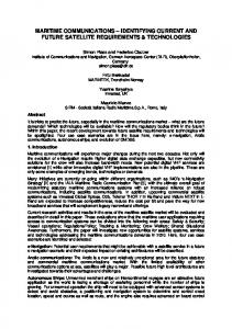
1.2. L IMIT- CYCLE OSCILLATIONS Limit-cycle oscillations (LCOs) are the simplest form of non-linear aeroelastic oscillations. In these oscillations the oscillation amplitude first grows (or decreases) and then stays constant, i.e. the oscillation amplitude remains limited, due to the presence of a non-linearity. Other, more complicated, non-linear aeroelastic responses include higher harmonic and sub-harmonic resonances, jump-resonances, entrainment, beating and period doubling [31]. Limit-cycle oscillations are often used as a prototype of a nonlinear aeroelastic response. Figure 1.1 shows an example of a time signal of an LCO and a phase plane view of an LCO.
α
α˙
1
time
(a) Oscillation amplitude versus time
α (b) Phase plane
Figure 1.1: A limit-cycle oscillation
For systems with aerodynamic non-linearities there exist two types of LCOs depending on the strength of non-linearity, i.e. LCOs can be either benign or detrimental. Figure 1.2 depicts these two types of LCOs. The variation of the LCO amplitude (or LCO mode shape) with, for example, the freestream velocity, as shown in Figure 1.2, is called the bifurcation behaviour. The dynamic pressure is another possible bifurcation parameter. In the case of flutter, i.e. when no non-linearities are present, the oscillation amplitude would increase unboudedly and hence this is represented in the bifurcation diagram by a vertical line at the flutter speed, see Figure 1.2. Benign LCOs occur beyond the flutter boundary. For a benign LCO, or more precisely, a supercritical Hopf bifurcation, the LCO amplitude increases with an increasing value of the bifurcation parameter. If the benign non-linearity is weak, the LCO amplitude will quickly grow when the airspeed or dynamic pressure is increased, i.e. the deviation from the linear case is small. If the non-linearity is strong, a smaller LCO amplitude will result and the deviation from the flutter case is large. These benign LCOs are always stable, i.e. they are attractors. If a disturbance causes a sudden oscillation amplitude increase or decrease then the system
4
1. I NTRODUCTION
LCO amplitude
will always return to the LCO state.
(linear) flutter
weak non-linearity
subcritical (GHWULPHQWDO) strong non-linearity
1
supercritical (EHQLJQ)
IOXWWHU VSHHG
Velocity
Figure 1.2: Two types of LCO as described by Dowell et al. [32]
The second LCO type that might occur is a detrimental LCO. Detrimental LCOs are those that would occur at airspeeds or dynamic pressures below the flutter boundary. Two LCOs would then exist below the flutter boundary, a stable and an unstable LCO. The unstable LCO is a so-called repeller, which separates two stable conditions (fixed points or LCOs). If a disturbance causes an amplitude increase such that the oscillation amplitude of the system is smaller than the unstable LCO amplitude, then the oscillation amplitude will decay to zero. If the oscillation amplitude after the disturbance is larger than the unstable LCO amplitude, a stable LCO results. For oscillations with initial amplitudes above the stable LCO amplitude, the amplitude will decay to the stable LCO amplitude, since the stable LCO is an attractor. In this manner LCOs might exist below the flutter boundary. In Figure 1.2 unstable LCOs are indicated by a dashed line. The red line indicates the so-called subcritical Hopf bifurcation, which exhibits hysteresis. When the freestream velocity is increased up to the flutter speed, and there is no disturbance larger than the unstable LCO amplitude, at the flutter speed any disturbance will cause a sudden amplitude increase up to the stable LCO amplitude. Then the LCO amplitude increases with freestream velocity. When the freestream velocity is decreased from a velocity above the flutter speed, the stable LCO amplitude decreases, until the point below which no LCOs exist (which is called a saddle-node bifurcation of limit cycles [33]) is reached. At this point the LCO amplitude will drop to zero, i.e. the LCO will disappear. If there is a disturbance larger than the unstable LCO amplitude at a velocity lower than the flutter speed but larger than the velocity at which the saddle-node bifurcation of LCOs occurs, then a stable LCO would occur below the flutter boundary.
1.3. P REVIOUS INVESTIGATIONS ON LIMIT- CYCLE OSCILLATIONS
5
1.3. P REVIOUS INVESTIGATIONS ON LIMIT- CYCLE OSCILLATIONS Several reduced-order models (ROMs) for limit-cycle oscillations caused by aerodynamic non-linearities have been developed. An overview is given in Section 1.3.1. Section 1.3.2 then describes the bifurcation behaviour of limit-cycle oscillations obtained from previous investigations with aerodynamic non-linearities. Finally, the remaining open questions are discussed in Section 1.3.3.
1.3.1. C OMPUTATIONAL METHODS To circumvent computationally expensive fluid-structure interaction (FSI) simulations, various researchers have developed alternative methods. This section presents an overview. A first alternative method is the aeroelastic harmonic balance (HB) method [34, 35]. This is a frequency domain method which uses an aerodynamic harmonic balance method to solve the governing fluid dynamic equations. In this aerodynamic HB method, the state variables of the flow are described using a Fourier series and then the governing fluid dynamic equations are solved in the frequency domain. Greco et al. [34] developed a frequency-domain transonic small-disturbance equations solver and Hall et al. [36] applied this procedure for the Euler equations. The frequency-domain fluid dynamic equations can easily be coupled to the equations of motion of an aeroelastic system. These equations of motion are then solved iteratively in the frequency domain. The aerodynamic forces are obtained from the HB flow solver at each iteration. Thomas et al. [35, 37–39] and Greco et al. [34] have demonstrated the prediction of limit-cycle oscillations caused by aerodynamic non-linearities by the harmonic balance method. Thomas et al. [37–39] used a RANS-based HB flow solver derived from Hall et al.’s Euler-based flow solver, whereas Thomas et al. [35] used the Euler-based HB solver [36]. Ekici and Hall [40] and Yao et al. [41] have suggested improvements for the coupling of the aerodynamic HB method and the aeroelastic equations of motion. Yao et al. [41] have shown that the results obtained with their aeroelastic harmonic balance method are in good agreement with those obtained from FSI simulations. The harmonic balance method allows for taking into account multiple harmonics in the structural motion and in the aerodynamic response. However, all investigations addressed above have only considered the first harmonic of the structural motion. For the aerodynamic response, in some cases, multiple harmonics were used. Application of the aeroelastic harmonic balance method significantly reduces the computational work compared to coupled time domain simulations, due to the harmonic balance CFD solver. Another method that can be used to investigate limit-cycle oscillations is to make use of neural networks. In that case a neural network is set up using a certain data set for training. The input to this network is the airfoil’s motion and the output are the aerodynamic forces. The network represents the relation between the applied airfoil motion and the aerodynamic forces. The equations of motion are then solved in the time domain with the aerodynamic forces predicted from the neural network. The LCO amplitude is predicted by applying a certain disturbance to the system and identifying the system’s response in time, similar as for fluid-structure interaction simulations. This approach has been demonstrated in [42–44]. Balajewicz and Dowell [42] found a good agreement with the bifurcation behaviour obtained from the harmonic balance method when the LCO amplitude was smaller than 3◦ . For larger amplitudes, no agreement was obtained
1
6
1
1. I NTRODUCTION
with the HB method results. Zhang et al. [44] and Mannarino and Mantegazza [43] compared their results with FSI simulations and observed good agreement when the neural network was sufficiently trained. A final approach is to use an extended version of a linearised frequency domain method that was actually developed to predict (linear) flutter, such as the p-k method or the k-method. The idea for this extended p-k method was first given by Ueda et al. [45], who used the transonic small disturbance equations as flow solver. The main idea is to take into account the amplitude-dependence of the aerodynamic forces instead of the frequency-dependence only (as in a linearised flutter analysis). Ueda et al. [45] did this using superposition of the aerodynamic forces for a two degree-of-freedom (DoF) airfoil system. To compute the aerodynamic forces a quasi-steady flow assumption was made, which in only valid for low reduced frequencies (< 0.3). Nevertheless, the method of Ueda et al. was found to be successful for stable LCOs of small amplitude (i.e. smaller than 0.5◦ ), in comparison to the results of time domain simulations. The validity of Ueda et al.’s method for larger amplitudes could not be proven, because of numerical instabilities of the flow solver during the reference time domain simulations. Recently, the extended version of the p-k method of Ueda et al. [45] has been used by He et al. [46]. He et al. [46] have dropped the quasi-steady flow assumption and instead used CFD simulations to compute the aerodynamic forces. They also applied superposition of the aerodynamic forces obtained from forced motions of each degree of freedom to obtain the total aerodynamic forces due to the motion of both degrees of freedom simultaneously. He et al. [46] have demonstrated their extended p-k method for different test cases using CFD simulations to compute the aerodynamic forces. Good agreement with other methods (harmonic balance method, direct time integration) was obtained when the non-linearity is weak. For stronger non-linearities deviations compared to the reference time-domain solution (and the harmonic balance solution) are present. Somieski [47] also applied superposition of non-linear forces in an eigenvalue method for the computation of limit-cycle oscillations of an aircraft nose landing gear. He used linear dynamic relations to relate one non-linearity to the other in case of multiple non-linearities in the aeroelastic system. In other words, a certain amplitude relation is chosen, dependent on the frequency, to represent the amplitudes of the other non-linearities as a function of that of the first non-linearity. The results of Somieski [47] were in excellent agreement with direct time domain computations.
1.3.2. L IMIT- CYCLE OSCILLATION BIFURCATION BEHAVIOUR The main sources of aerodynamic non-linearity of interest for (civil) transport aircraft are moving shock waves and unsteady interactions of these shock waves with the boundary layer. Therefore, most of the previous investigations into the bifurcation behaviour of limit-cycle oscillations have been performed in the transonic flow regime. This flow regime is also the main focus of this thesis. However, limit-cycle oscillations have also been observed in subsonic flows with boundary-layer transition and flow separation. Since, the motivation of this thesis is whether and at which flow conditions subcritical bifurcations occur, a short overview of these limit-cycle oscillations is also presented here. Numerous investigations have been performed in transonic flow in which various
1.3. P REVIOUS INVESTIGATIONS ON LIMIT- CYCLE OSCILLATIONS
7
airfoils have been studied. Schewe et al. [48] and Dietz et al. [49, 50] performed windtunnel experiments with the NLR7301 airfoil. Therefore, this airfoil is often used for numerical studies of limit-cycle oscillations. Several researchers [22, 23, 25, 26, 28–30, 37, 51–53] investigated LCOs of the NLR7301 airfoil using either fluid-structure coupling or the harmonic balance method. However, few have considered the bifurcation behaviour of the LCOs found for this airfoil. Thomas et al. [37] studied the bifurcation behaviour of the LCO (pitch) amplitude with the HB method using both viscous and inviscid modelling of the aerodynamics. When the flow was inviscid a large LCO amplitude was found, i.e. the non-linearity is apparently very weak. However, for the viscous case a supercritical bifurcation was observed with smaller amplitudes. Hence, from this study it was concluded that viscous effects are important when studying LCOs caused by aerodynamic non-linearities. The bifurcation behaviour of the NACA64A010A airfoil was studied by various researchers [43, 44, 54–56] using the same linear structural model. Benign LCOs were found at M∞ = 0.8 and α0 = 0◦ in inviscid flow [43, 44, 56]. Kholodar et al. [54, 55] have performed an extensive study on the LCO behaviour of the NACA64A010A airfoil under the variation of two structural parameters (mass ratio and uncoupled natural frequency ratio) using the harmonic balance method in combination with a flow solver for the Euler equations. They found that the mass ratio does not significantly influence the type of LCO behaviour unless the non-linearity is weak. The uncoupled natural frequency ratio was found to influence the stability and the eigenform of the LCOs. When this ratio is increased from 0.5 to 1.8, the LCOs are first stable (supercritical), then become weak and finally unstable (subcritical). The eigenform changes from plunge dominated to a complex pitch/plunge motion to pitch dominated when the frequency ratio is increased. The Mach number was observed to influence the strength of the non-linearity significantly. Small LCO amplitudes, caused by strong non-linearities, were only found in a very limited Mach number range [54, 55]. Kousen and Bendiksen [57] have studied the NACA64A006 airfoil using fluid-structure coupling of the Euler equations with a linear structural model. They found supercritical bifurcation behaviour of the LCO amplitude at several transonic Mach numbers in range from 0.85 to 0.92. At M = 0.25 and M = 0.6, the oscillations were still growing in amplitude after sixty oscillation cycles. Balajewicz and Dowell [42] and Zhang et al. [44] have studied the NACA0012 airfoil in inviscid flow numerically using neural networks and found supercritical LCOs (each using a slightly different linear structural model though). In addition, Balajewicz and Dowell [42] also used the HB method for the NACA0012 airfoil in inviscid flow. From this method unstable LCOs were observed at M = 0.7 and M = 0.8. At M = 0.95 both methods predicted a supercritical bifurcation. Raveh and Dowell [58] have also used the NACA0012 airfoil in their study of transonic aerodynamic buffet. They observed LCOs at dynamic pressures below the linearly predicted flutter dynamic pressure when the natural frequencies of their two degree-of-freedom system are close to the buffet frequency. All of the studies mentioned above considered limit-cycle oscillations in transonic flow. However, limit-cycle oscillations can also occur in subsonic flow, even incompressible flow at low Reynolds numbers. Poirel et al. [24, 59–61] and Yuan et al. [62] studied
1
8
1
1. I NTRODUCTION
the NACA0012 airfoil at Reynolds numbers ranging from 4.5· 104 to 1.3· 105 , both experimentally and numerically. The airfoil was assigned either one (pitch) or two degrees of freedom (pitch, plunge). Limit-cycle oscillations of small amplitude (