2011has raised the issue of revision in IS code 2062 as follows: ... B1-2001, the
various grades of steel as per IS 2062-1999 has been mentioned. But.
Hkkjr ljdkj & jsy ea=ky; GOVERNMENT OF INDIA MINISTRY OF RAILWAYS
16 ,oa 17 Qjojh & 2012 esa
tcyiqj esa gksus okyh iqy ,oa lajpuk ekud lfefr dh
bD;klhoha cSBd dh dk;Zlwph Agenda Of
Eighty First Meeting Of Bridge & Structures Standards Committee (16th & 17th February - 2012) At
Jabalpur
vuqla/kku vfHkdYi vkSj ekud laxBu y[kuÅ&226011 RESEARCH DESIGNS AND STANDARDS ORGANISATION LUCKNOW-226011
81st MEETING OF BRIDGE AND STRUCTURES STANDARDS COMMITTEE (February, 2012)
SUBJECT INDEX
Item No.
Title of the Item
Page No.
1027
Revision in Paints Specification for finishing coat due to withdrawal of Red Oxide Paint to IS: 123.
1-5
1028
Amendment in para 8.1 to 8.4 of IRS B1-2001 due to amendment No. 1 in IS 2062:2006.
6-17
1029
Standard drawing of H-beam steel sleeper for use of welded girder bridges (BG).
18
1030
Frequency of C & G of Bearings.
19-20
1031
Provision of Phosphor Bronze Bearing on both ends of girder.
21-22
1032
Reduction in longitudinal load in case of bridges having more than two tracks.
23-43
1033
Review of action taken on pending items
44-82
**********
ii
81st MEETING OF BRIDGE AND STRUCTURES STANDARDS COMMITTEE (February, 2012) ITEM NO. 1027
Subject
:
Revision in Paints Specification for finishing coat due to withdrawal of Red Oxide Paint to IS: 123.
BSC Reference
:
Railway Board‟s letter No.2005/CE-I/BR-II/11/RDSO dated 28-12-2011 and CBE/W.C.Rly.‟s letter No. W65/BSC/Meeting dated 14-12-2011.
RDSO File No.
:
CBS/MPP.
Agenda
:
Due to withdrawal of Red Oxide Paint to IS: 123, the specification for finishing coat paint needs to be revised. NOTES BY SECRETARY
1. Para 217 of Bridge Manual deals with protective coatings by painting with alkyd based paints & sub para 217(2) deals with choice of suitable paints. Sub Para 217.2(a) (ii) and para 217.2 (c) prescribes finishing coat with 2 coats of ready mixed Red Oxide paint to IS;123. Bureau of Indian Standards has withdrawn Red Oxide paint to IS;123 and replaced it with finishing paint to IS:13607. Hence, necessary modifications are required in corresponding paras of Bridge Manual and IRS B-12001 which have reference of finishing coats with Red Oxide paint to IS:123. After withdrawal of red Oxide paint to IS:123, M&C Directorate has drafted RDSO specification No. M&C/PCN/122/06 and has recommended for use of same in place of Ready Mix Red Oxide paint as per IS:123. The necessary correction slip was proposed to Board where Board desired that this should be discussed in next BSC. In pursuance it was further examined and discussed in detail with M&C Directorate. It is gathered that M&C specifications are generally similar to IS:13607 (Revised code in lieu of IS:123). M&C Directorate approves vendors for supply of paints for various department of Railways and there are only 7 approved vendors; (2 in Part-I and 5 in Part-II) for supply of paint to RDSO specification No. M&C/PCN/122/06. These vendors are concentrated in Kolkata and Lucknow region. M&C Directorate /RDSO also approves vendors for IS:13607 and there are 26 (17 in Part-I and 9 in Part-II) approved vendors for supply of paints to IS:13607. The general properties of finishing paint as per IS:13607 are similar to IS:123 except the flexibility of choosing the colour/shade of paint. Whenever orders are to be placed as per IS-13607 the purchaser has to specify the colour/shade. The prescribed shelf life of finishing paint to IS:13607 is also one year. Looking to the logistic of availability the flexibility can be provided to user to use paint either as per RDSO Specification No. M&C/PCN/122/06 or as per IS:13607 in lieu of Red Oxide as per IS:123 which has been with drawn.
1
81st MEETING OF BRIDGE AND STRUCTURES STANDARDS COMMITTEE (February, 2012) Item No. 1027 continued…. 2. Para 217(e) of Bridge Manual prescribe shelf life of various type of paints. However, shelf life of Zinc chrome paint to IS:104 and Zinc chrome red oxide paint to IS: 2074 are not mentioned. These paints are used as primer coat for Alkyd based coating system as given in clause 39.2.3(ii) of IRS:B-1. CBE/WCR has made a reference to prescribe the shelf life of these paints also. Though the shelf life is given in the relevant IS code. However, it can be mentioned in para 217.4 (e) of Bridge Manual where shelf life of other paints are given. The shelf life of both paints is one year. 3. Some other codes issued by M&C Directorate of RDSO have also been revised. Para 3.3 of IRS B1-2001 needs to be revised mentioning the latest revision. 4. Para 12.3 of BS-45: “Guidelines on Fabrication of steel Channel Sleepers” deals with galvanizing and painting of steel channel sleeper. There was a reference from N.E.Rly for requirement of painting on channel sleepers even after hot dip galvanizing. The issue was examined and discussed with M&C Dte as well as with field officials and it is felt that after hot dip galvanizing no major purpose is served by painting it. Also painting of channel sleepers on the inner side is practically impossible. Hence, the provision of painting on channel sleepers after galvanizing which was a optional provision can be deleted for which a draft correction slip to para 12.3 of BS-45 is required to be issued. In view of above details draft correction slip is prepared for the consideration of BSC as follows:Para 217. of Indian Railway Bridge Manual 217.2 (a) (ii) Existing Finishing Coat : Two cover coats of Red-oxide paint to IS:123 or any other approved paint applied over the primer coats.
Revised Finishing Coat: Two cover coats of paint to IS:13607 with colour/shade to be specified by Zonal Railway OR Two coats of paint as per RDSO specification No. M&C/PCN/122/06 applied over the primer coats. Note: (i) The colour/shade of finishing coat should be generally matching with the Red Oxide colur/shade No. ISC 446 mentioned in IS5:2004. (ii) The colour/shade can be changed by CBE as per the local reqirements.
2
81st MEETING OF BRIDGE AND STRUCTURES STANDARDS COMMITTEE (February, 2012) Item No. 1027 continued…. Para 217. 2. (c) Existing In case where the priming coat is in good condition the steel work is painted with two coats of ready mixed red oxide paint to IS:123 or paint aluminium to IS:2339 depending on the severity of corrosion.
Revised In case where the priming coat is in good condition the steel work is painted with two coats of paint to IS:13607 with colour/shade to be specified by Zonal Railway OR paint aluminium to IS:2339 depending on the severity of corrosion. Note: (i) The colour/shade of finishing coat should be generally matching with the Red Oxide colur/shade No. ISC 446 mentioned in IS5:2004. (ii) The colour/shade can be changed by CBE as per the local reqirements.
Para 217.4.(e) Existing e) Paints should be used within the prescribed shelf life from the date of manufacture. The quantity of paint procured should be such that it is fully utilised before the period prescribed for its use. The shelf life of various paints used in the Railways are as follows: i) Paint Red Lead Ready Mixed (IS : 102): 4 months ii) Paint Red Oxide Ready mixed (IS : 123): 1 year iii) Paint aluminium : When paste and oil are not mixed: 1year When paste and oil are mixed: 4 months iv) Oil linseed boiled: 2 years v) Red lead dry paint: (No time limit.)
Revised e) Paints should be used within the prescribed shelf life from the date of manufacture. The quantity of paint procured should be such that it is fully utilised before the period prescribed for its use. The shelf life of various paints used in the Railways are as follows: i) Paint Ready mixed Zinc Chromate Primer (IS : 104): 1 Year ii) Paint to IS:13607 with colour/shade to be specified by Zonal Railway: 1 year iii) Paint aluminium : When paste and oil are not mixed: 1year When paste and oil are mixed: 4 months iv) Oil linseed boiled: 2 years v) Paint ready mixed Red Oxite Zinc Chrome (IS:2074): 1 year
3
81st MEETING OF BRIDGE AND STRUCTURES STANDARDS COMMITTEE (February, 2012)
Item No. 1027 continued…. Para: 39.2.3 (b) of IRS B1-2001 Finishig coat Existing Two finishing coats of red oxide paint to IS:123 or of any other approved paint shall be applied over the primer coats. One coat shall be applied before the fabricated steel work leaves the shop. After the steel work is erected at site the second finishing coat shall be applied after touching up the primer and the finishing coat if damaged in transit.
Revised Two finishing coats of paint to IS:13607 with colour/shade to be specified by Zonal Railway OR Two coats of paint as per RDSO specification No. M&C/PCN/122/06 shall be applied over the primer coats. One coat shall be applied before the fabricated steel work leaves the shop. After the steel work is erected at site the second finishing coat shall be applied after touching up the primer and the finishing coat if damaged in transit. Note: (i) The colour/shade of finishing coat should be generally maching with the Red Oxide colur/shade No. ISC 446 mentioned in IS5:2004. (ii) The colour/shade can be changed by CBE as per the local reqirements.
Para 0.3.3 of of IRS B1-2001
M&C/PCN/102/96 M&C/PCN/103/86 M&C/PCN/109/88 M&C/PCN/110/88 M&C/PCN/111/88
Existing Epoxy zinc phosphate primer. Epoxy micaceous iron oxide. Polyurethane red oxide. Polyurethane aluminium. High build Epoxy paint.
To be replaced by M&C/PCN/102/2009 Epoxy zinc phosphate primer. M&C/PCN/103/2011 Epoxy micaceous iron oxide. M&C/PCN/109/2009 Polyurethane red oxide. M&C/PCN/110/2006 Polyurethane aluminium. M&C/PCN/111/2006 High build Epoxy paint. M&C/PCN/122/2006 Ready Mix Red Oxide Paint
4
81st MEETING OF BRIDGE AND STRUCTURES STANDARDS COMMITTEE (February, 2012)
Item No. 1027 continued…. Para 12.3 of BS 45 - Guidelines on Fabrication of Steel Channel Sleepers:Existing To be replaced by For most applications, the galvanized The galvanized channel sleepers do not channel sleepers do not need any paint need any paint coating. coating. However, in order to prolong the protection given by galvanizing the galvanized channel sleepers shall be painted with one coat of ready mixed paint Red Oxide Zinc Cromate conforming to IS:2074 followed by one coat of Aluminium paint conforming to IS:2339.
Committee may deliberate and make recommendations. **********
5
81st MEETING OF BRIDGE AND STRUCTURES STANDARDS COMMITTEE (February, 2012) ITEM NO. 1028
Subject
:
Amendment in para 8.1 to 8.4 of IRS B1-2001 due to amendment No. 1 in IS 2062:2006.
BSC Reference
:
CBE/N. Railway letter No. 65-W/1/67/W.BR. dated 25-102011. Related BSC Item No. 943 of 77 th BSC.
RDSO File No.
:
CBS/GSP.
Agenda
:
Revision in IRS B1-2001 due to amendment No. 1 issued for IS 2062 : 2006.
NOTES BY SECRETARY
CBE Northern Railway vide his letter No. 65-W/1/67/W.BR. dated 25-102011has raised the issue of revision in IS code 2062 as follows: “As per RDSO drawings, the material for fabrication of steel girders should be as per fabrication specification B1-2001. In clause no. 8 of fabrication specification B1-2001, the various grades of steel as per IS 2062-1999 has been mentioned. But IS 2062-1999 (steel for general structural purposed specification) has since been replaced by IS 2062-2006 (hot rolled low, medium and high tensile structural steel) which has been further amended in March 2009 by amendment No. 1. In these revision & amendments, grade designation, quality and other specification have significant changes as compared to 2062-1999. Grade B has been split into BR and BO.” Indian Railway Standard Specification for Fabrication and Erection of Steel Girder Bridges and Locomotive Turntable (Fabrication Specification) Serial No. B12001 deals with the different type of steels to be used in fabrication of Steel Girder Bridges. This document prescribe use of grade-B E250 (FE410) steel as per IS2062. In 2001, IS2062-1999 was current code and provision were made accordingly. With the revision of IS:2062 in 2006 changes were discussed under Item 943 of 77th BSC and based on recommendations of BSC and with approval of Railway Board, A&C No. 4 was issued to IRS B1-2001 vide letter No. CBS/GSP dated 01-08-2008. This correction slip includes all modification done in IS2062 by 2006. Four types of grade of steel as per IS:2062 have been prescribed for girder fabrication as per IRS B1-2001 in para 8.1 to 8.4. Para
Remarks
8.1 IS:2062 Quality A grade E-250 Suitable for Foot Over Bridges and (Fe410W) Semi killed or killed other structures subjected to noncritical loading
6
81st MEETING OF BRIDGE AND STRUCTURES STANDARDS COMMITTEE (February, 2012) Item No. 1028 continued…. 8.2 IS:2062 Quality B Grade E-250 Suitable for welded/riveted girders (Fe410W)fully killed & fully where service temperature does not fall normalized below 00C. 8.3 IS:2062 Quality C Grade E-250 Suitable for welded as well as riveted (Fe410w) with impact test at 200C girders in sub-zero temperature area. or -400C, Fully killed & normalized. Note: Rolled Sections like angles, channels, I-sections etc., conforming to IS:2062 Quality „A‟ may be used in structures till such time rolled sections conforming to IS:2062 Quality B/C are not available in the market. 8.4 High tensile steel to IS:2062-2006 High tensile steel Quality D (both Quality E 410 (Fe540) or E 450 (Fe copper bearing quality) Suitable for 570) Quality D semi killed or killed. welded or riveted work respectively. In 2009 further revision has been done in IS:2062 vide amendment No. 1 and salient feature are as follows:The salient features of revisions are: (i)
In the new amendment 4 quality category have been prescribed for all grades of steel from E250(FE410) to E450(FE570). Also more category of higher strength steel E550(FE650) to E650(FE780) have been included having two quality types. We in Railway mainly use E250 and for the some exceptional cases high tensile steel E450 is being used. Four quality types are: A
Impact test not required, semi-killed/killed.
BR
Impact test optional: at room temperature if required, killed (Room temperature is defined as 25+ 2 Deg.C).
B0
Impact test mandatory at 0 Deg.C, killed.
C
Impact test mandatory at -20 Deg.C, killed.
(ii)
In IS;2062 2006 version quality types A, B, C, D & E were mentioned and a charpy impact value were applicable as per the mutual agreement between purchaser and supplier. In 2009 version charpy impact tests is mandatory for B-0 and C quality type. The chemical composition and Carbon equivalent for corresponding grade of steel is same.
(iii)
In IS:2062 2006 version E165 grade (FE290) was prescribed which has been deleted from 2009 version. However, as per B-1 document this steel was not included for use in Railway bridges.
(iv)
In Table-1 of IS:2062 showing Chemical Composition following note has been added as note number 10 below the table “Alloying elements such as Cr, Ni and Mo may be added singly or in combination and shall not be more than 0.50% for E600 and 0.60% for E 650.”
7
81st MEETING OF BRIDGE AND STRUCTURES STANDARDS COMMITTEE (February, 2012) Item No. 1028 continued…. (v)
In clause 9.1 of IS: 2062 following note has been added below the existing clause:“Note:- However, in case of the plates beyond 12mm in thickness, produced from cutting of HR coil, the sample for tensile testing shall be taken only in transverse direction.”
Table of chemical composition and mechanical properties have been replaced as given below. (A)
Chemical composition and mechanical properties of structural steel as per IS:2062-2006 are as under:Chemical Composition (Classes 5.8.1 and 8.2)
Grade Designation Quality
1 E 165 (Fe 290) E 250 (Fe 410 W) E 250 (Fe 410 W) E 250 (Fe 410 W) E 300 (Fe 440) E 350 (Fe 490) E410 (Fe 540) E 450 (Fe 570) E 450 (Fe 590)
2 A B C D E
Ladle Analysis, Percent, Max.
C 3 0.25 0.23 0.22 0.20 0.20 0.20 0.20 0.22 0.22
Mn 4 1.25 1.50 1.50 1.50 1.30 1.50 1.60 1.60 1.80
S 5 0.045 0.045 0.045 0.040 0.045 0.045 0.045 0.045 0.045
P 6 0.045 0.045 0.045 0.040 0.045 0.045 0.045 0.045 0.045
Si 7 0.40 0.40 0.40 0.45 0.45 0.45 0.45 0.45
Carbon Equivalen t (CE), Max 8 0.42 0.41 0.39 0.40 0.42 0.44 0.46 0.48
De- oxidation Mode
9 Semi-killed or Killed Semi-killed or Killed Killed Killed Semi-killed or Killed Semi-killed or killed Semi-killed or killed Semi-killed or killed Semi-killed or killed
NOTES 1.
Carbon equivalent (CE) Based on ladle analysis
2.
When the steel is killed by aluminium alone, the total aluminium content shall not be less than 0.02 percent. When the steel is killed by silicon alone, the silicon content shall not be less than 0.10 percent. When the steel is silicon-aluminium killed, the silicon content shall not be less than 0.03 percent and total aluminium content shall not be less than 0.01 percent.
3.
Microalloying elements like Nb, V, Ti and B shall be added singly or in combination. Total microallolying elements shall not be more than 0.25.
4.
New grades designation system based on yield stress has been adopted, simultaneously old designations have also been given in parentheses.
5.
Steels of qualities A, B and C are generally suitable for welding processes. The weldability increases from quality A to C.
6.
Copper may be present between 0.20 to 0.35 percent as mutually agreed to between the purchaser and the manufacturer. The copper bearing quality shall be designated with a suffix Cu, for example, E 250 Cu. In case of product analysis the copper content shall be between 0.17 and 0.38 percent.
7.
Nitrogen content of steel shall not exceed 0.012 percent which shall be ensured by the manufacturer by occasional check analysis. For micro alloyed steel this is to be reduced to 0.009 percent.
8.
The steel if required may be treated with rare earth element for better formability.
9.
Lower limits for carbon equivalent and closer limits for other elements may be mutually agreed to between the purchaser and the manufacturer.
10.
Incidental element- Elements not quoted in Table 1 shall not be intentionally added to steel without the agreement of the purchaser, other than for the purpose of finishing the heat. All reasonable precautions shall be taken to prevent the addition from scrap or other materials used in manufacture of such elements which affect the hardenability, mechanical properties and applicability.
8
81st MEETING OF BRIDGE AND STRUCTURES STANDARDS COMMITTEE (February, 2012)
Item No. 1028 continued…. Mechanical Properties (Clauses 5, 10.3, 10.3.1) Grade Designation Quality
Tensil e Streng th Min., MPa
2
Yield Stress. Min., MPa 40
Percent Elongatio n at Gauge Length, L0
Charpy VNotch Impact Energy J, Min.
Room -20 C Temp. 10 11
So
5.65 mm
mm
mm
Min
25
4
5
6
7
8
9
0
1 E 165 (Fe 290)
-
290
23
2t
-
-
-
E 250 (Fe 410 W)
A
410
250
240
230
23
3t
2t
-
-
E 250 (Fe 410 W) E 250 (Fe 410 W)
B C
410 410
250 250
240 240
230 230
23 23
2t 2t
3t 3t
27 see note 3 27 see note 3
E 300 (Fe 440)
-
440
300
290
280
22
2t
3t
50
30
E 350 (Fe 490) E410 (Fe 540)
-
490
350
330
320
22
2t
3t
50
25
540
410
390
380
20
2t
3t
50
25
E 450 (Fe 570)
D
570
450
430
420
20
2t
3t
45
20
E 450 Fe 590
E
590
450
430
420
20
2t
3t
45
20
Note 1.
3
Internal Diameter of Bend (Min)
165
2
2
2
1 MPa = 1N/mm = 1MN/m = 0.102 kgf/mm = 144.4 psi
2.
Temperature of Charpy impact values will be subject to mutual agreement.
3
The more stringent requirements than those given above may be as agreed to between the purchaser and the manufacturer.
(B) Chemical composition and mechanical properties of structural steel as per Amendment No. 1 of March 2009 (copy placed as annexure-A) to IS:2062-2006 are as under:Chemical Composition (Classes 5.8.1 and 8.2) Grade Designation Quality
1 E250
E 300
E 350
E410
2 A BR B0 C A BR B0 C A BR B0 C A BR B0 C BR
Ladle Analysis, Percent, Max.
C 3 0.23
Ma 4 1.50
S 5 0.045
P 6 0.045
Si 7 0.40
Carbon Equivalen t (CE), Max 8 0.42
Method of Deoxidation
0.22
1.50
0.045
0.045
0.40
0.41
Killed
0.20
1.50
0.040
0.40
0.40
0.39
Killed Semi-killed/killed
0.20
1.30
0.045
0.045
0.45
0.40
9 Semi-killed/killed
Killed Semi-killed/killed
0.20
1.50
0.045
0.045
0.45
0.42
Killed Semi-killed/killed
0.20
1.60
0.045
0.045
0.45
0.46
Killed Killed
9
81st MEETING OF BRIDGE AND STRUCTURES STANDARDS COMMITTEE (February, 2012) Item No. 1028 continued…. E450 E 550 E 600 E 650
A BR A BR A BR A
0.22
1.60
0.045
0.045
0.45
0.48
0.22
1.65
0.020
0.025
0.50
0.50
0.22
1.70
0.020
0.025
0.50
0.50
0.22
1.70
0.024
0.025
0.50
0.52
Semi-killed/killed Killed Semi-killed/killed Killed Semi-killed/killed Killed Semi-killed/killed
NOTES 1.
Carbon equivalent (CE) Based on ladle analysis
2.
When the steel is killed by aluminium alone, the total aluminium content shall not be less than 0.02 percent. When the steel is killed by silicon alone, the silicon content shall not be less than 0.10 percent. When the steel is silicon-aluminium killed, the silicon content shall not be less than 0.03 percent and total aluminium content shall not be less than 0.01 percent.
3.
Microalloying elements like Nb, V, Ti and B shall be added singly or in combination. Total microallolying elements shall not be more than 0.25.
4.
New grades designation system based on yield stress has been adopted
5.
Steels of qualities A, BR, B0 and C are generally suitable for welding processes. The weldability increases from quality A to C for grade designation E 250.
6.
Copper may be present between 0.20 to 0.35 percent as mutually agreed to between the purchaser and the manufacturer. The copper bearing quality shall be designated with a suffix Cu, for example, E 250 Cu. In case of product analysis the copper content shall be between 0.17 and 0.38 percent.
7.
Nitrogen content of steel shall not exceed 0.012 percent which shall be ensured by the manufacturer by occasional check analysis.
8.
The steel if required may be treated with rare earth element for better formability.
9.
Lower limits for carbon equivalent and closer limits for other elements may be mutually agreed to between the purchaser and the manufacturer.
10.
Alloying elements such as Cr, Ni and Mo may be added singly or in combination and shall not be more than 0.50% for E600 and 0.60% for E 650
11.
Incidental element- Elements not quoted in Table 1 shall not be intentionally added to steel without the agreement of the purchaser, other than for the purpose of finishing the heat. All reasonable precautions shall be taken to prevent the addition from scrap or other materials used in manufacture of such elements which affect the hardenability, mechanical properties and applicability.
10
81st MEETING OF BRIDGE AND STRUCTURES STANDARDS COMMITTEE (February, 2012) Item No. 1028 continued…. Mechanical Properties (Clauses 5, 10.3, 10.3.1) Grade Designation Quality
1
2
Tensil e Streng th Min., MPa
Yield Stress. Min., MPa 40
Percent Elongatio n at Gauge Length
Charpy VNotch Impact Energy J, Min.
Room -20 C Temp. 10 11
So
5.65
3
Internal Diameter of Bend (Max.) (See Note 2)
mm
mm
mm
Min
25
4
5
6
7
8
9
A
-
-
RT
27
C
0 (-) 20
27 27
A
-
-
BR B0
RT
27
BR
E 250
B0
E 300
E 350
E 410
410
440
250
300
240
290
230
280
23
22
2t
2t
3t
-
0
27
C
(-)20
27
A
-
-
BR B0
RT 0
27 27
C
(-)20
27
A
-
-
BR
RT
25
0
25
(-) -
25 -
RT
20
0
20
C
(-)
20
A
-
-
RT
15
RT
15
-
-
RT
15
B0
490
540
350
410
330
390
320
380
22
20
2t
2t
-
-
C A BR
E 450
B0
E 550
BR A
E 600
BR A
E 650
BR Note
0
570
650
450
550
430
530
420
520
20
12
2.5t
3.0t
-
-
730
600
580
570
12
3.5t
-
780
650
630
620
12
4.0t
-
2
2
2
1.
1 MPa = 1N/mm = 1MN/m = 0.102 kgf/mm = 144.4 psi
2.
Bend test not required for thickness > 25mm for grades E300 to E650 „t‟ is the thickness of the test piece.
3.
For sub-quality BR, impact test is optional at room temperature (25+20C), if required.
All changes were discussed in consultation with M&C Directorate of RDSO and amendments are proposed in para 8.1 to 8.4 of IRS B1-2001.
11
81st MEETING OF BRIDGE AND STRUCTURES STANDARDS COMMITTEE (February, 2012) Item No. 1028 continued…. In accordance to above, the correction slip was prepared and sent to Railway Board for approval. However Railway Board vide their letter No. 2005/CE-I/BRIII/11/RDSO dated 28-12-2011 desired that amendment proposed should be deliberated in BSC Meeting so that associated field issues, if any, also get due consideration. The proposed amendment IRS B1-2001 is as follows:Para 8 of IRS B1-2001 Existing
Revised
8.1 IS:2062, Quality “A” Grade Designation E250 (Fe 410 W) as rolled semi-killed or killed shall be used for foot-over bridges and other structures subjected to noncritical loading.
8.1 IS:2062, Quality “A” Grade Designation E250 as rolled semi-killed or killed shall be used for foot-over bridges and other structures subjected to non-critical loading.
8.2 IS:2062, Quality “B” Grade Designation E250 (Fe 410 W) fully killed and normalized/controlled cooled, where service temperature does not fall below 0 0C, shall be used for welded/riveted girders subjected to Railway loading. Plates less than 12mm thick need not be normalized/controlled-cooled.
8.2 IS:2062, Quality “B0” Grade Designation E250 fully killed and normalized/controlled cooled, where service temperature does not fall below 00C, shall be used for welded/riveted girders subjected to Railway loading. Plates less than 12mm thick need not be normalized/controlledcooled but should be fully killed.
8.3 IS:2062, Quality “C” Grade Designation E250 (Fe 410 W) fully killed and normalized/controlled cooled, ensuring impact properties at (-) 200 C or (-) 400 C shall be used for sub-zero temperature areas for welded/riveted girders subjected to Railway loading. Plates less than 12mm thick need not be normalized/controlledcooled.
8.3 IS:2062, Quality “C” Grade Designation E250 fully killed and normalized/controlled cooled, ensuring impact properties at (-) 200 C shall be used for sub-zero temperature areas for welded/riveted girders subjected to Railway loading. Plates less than 12mm thick need not be normalized/controlled-cooled but should be fully killed.
NOTE: Rolled Sections like angles, channels, I-sections etc., conforming to IS:2062 Quality „A‟ may be used in structures till such time rolled sections conforming to IS: 2062 Quality B/C are not available in the market.
NOTE: In case Rolled Steel Section confirming to IS:2062 Quality “B0” or “C” are not available in market, CBE may permit use of steel confirming to IS:2062 Quality “A” for noncritical members on case to case basis, by satisfying himself about non availability of quality B0 or C.
12
81st MEETING OF BRIDGE AND STRUCTURES STANDARDS COMMITTEE (February, 2012) Item No. 1028 continued…. 8.4 High tensile steel shall comply in all respects with the requirement of IS:20622006 Grade Designation E 410 (Fe 540) or E 450 (Fe 570) Quality D (both copper bearing quality) according to the welded or riveted work respectively.
8.4 High tensile steel shall comply in all respects with the requirement of IS:2062 Grade Designation E 410 Quality B0 or C or E 450 Quality B0/C (both copper bearing quality) according to welded or riveted work respectively.
Committee may deliberate and make recommendations.
**********
13
81st MEETING OF BRIDGE AND STRUCTURES STANDARDS COMMITTEE (February, 2012)
Item No. 1028 continued…. Annexure-A
14
81st MEETING OF BRIDGE AND STRUCTURES STANDARDS COMMITTEE (February, 2012) Item No. 1028 continued….
15
81st MEETING OF BRIDGE AND STRUCTURES STANDARDS COMMITTEE (February, 2012) Item No. 1028 continued….
16
81st MEETING OF BRIDGE AND STRUCTURES STANDARDS COMMITTEE (February, 2012) Item No. 1028 continued….
**********
17
81st MEETING OF BRIDGE AND STRUCTURES STANDARDS COMMITTEE (February, 2012) ITEM NO. 1029
Subject
:
Standard drawing of H-beam steel sleeper for use of welded girder bridges (BG).
BSC Reference
:
Nil
RDSO File No.
:
CBS/Project/H.B. Sleeper
Agenda
:
To examine the drawing of steel H-beam sleepers prepared by R.D.S.O. and make recommendations. NOTES BY SECRETARY
1. RDSO has developed the drawings of H-beam sleeper for axle load upto 32.5t and drawing No. RDSO/B-1636/8 have been sent to Railways for scrutiny and comments vide letter no. CBS/Project/H. beam sleeper dated 18-08-2010. 2.
Design Features:
The design has been done in accordance with IRS Steel Bridge Code, IRS Bridge Rules, IRS Welded Code. This drawing has been developed for providing HBeam sleepers on girders where top flange does not have any rivets. The salient features are as below : (i) (ii) (iii)
Load capacity – Axle load upto 32.5t Section – ISHB 200x200 @37.3 kg/m has been used. Material – Material considered is steel as per IS 2062 Grade „B‟
3. Position of holes and Rail fastening assembly shall be given by Track directorate of RDSO. 4. 20mm diameter HSFG bolt has been used to connect the top flange of girder with the H-beam sleeper for proof load of 147 KN. 5. Hot dip galvanizing to be done as per IS:4759 to prevent corrosion. However CBE may permit use of Steel H-Beam sleepers with painting as per para 218 of IRBM on economic and other practical grounds. The new design and provisional drawing no. RDSO/B-1636/8 is put up for Committee considerations and views.
**********
18
81st MEETING OF BRIDGE AND STRUCTURES STANDARDS COMMITTEE (February, 2012) ITEM NO. 1030
Subject
:
Frequency of C & G of Bearings.
BSC Reference
:
Nil
RDSO File No.
:
CBS/Bearing
Agenda
:
As per Bridge manual para 222.2(a) C & G of bridge bearings is to be carried out once in three years. This frequency was fixed when traffic density was very low. Since number of the trains increased considerably frequency of C & G may be reduced to 2 years. NOTES BY SECRETARY
The Bridge bearing is an element of superstructure which provides an interface between the superstructure and substructure. This interface is vital because superstructure undergoes dimensional changes and deformations due to various factors like: (a) Thermal expansion/contraction. (b) Elastic deformation under live load. (c) Seismic forces. (d) Creep and shrinkage of concrete. (e) Settlement of supports. (f) Longitudinal forces-Tractive/Braking. (g) Wind loads. If these movements between superstructure and substructure are not allowed to take place freely, large amount of forces may develop in the girder/substructure. It is therefore necessary to permit relative movement between the superstructure and substructure. Since the bearing is introduced for accommodating the various permitted movements, it has to transfer entire load from superstructure to substructure of bridge. There are different types of bearings based on permitted degree of freedom and type of material used. In those types of bearing where there is relative movement between steel to steel like sliding bearing, Roller and Rocker bearing etc. the condition of contact surface plays an important role. Entrapment of dirt, debris and corrosion of steel can increase the coefficient of friction considerably and it may even cause the bearings to freeze. When bearings are frozen, a large amount of longitudinal force is transferred to the substructure for which it may not have been designed. Sometimes even repairs will not hold good if bearings are not properly greased.
19
81st MEETING OF BRIDGE AND STRUCTURES STANDARDS COMMITTEE (February, 2012) Item No. 1030 continued…. The para 222.2(a) of IRBM stipulates that Cleaning and Greasing of all sliding and Roller & Rocker bearings should be done once in three years. This stipulation is not related to the amount of traffic passing over the Bridge. It has been proposed to change the frequency of C & G to 2 years on routes with heavy traffic. The bearings are greased by lifting the girders and may require traffic blocks of adequate duration. Proper jacking arrangements are required for lifting the girders and adequate precautions are to be taken during C & G of the bearings. If we increase the frequency of C & G, the manpower & block requirements will increase. To reduce the efforts in greasing, para 222(b) of IRBM states that “Oil Bath Bearings are generally provided for new girders of span above 76.2m and for other Open Web Girders, whether new or existing, in case it is consider difficult to lift the girder for periodic greasing” may be provided. For sliding bearing, use of phosphor bronze bearing can reduce the efforts required for greasing by 50%. The committee is requested to deliberate on this issue.
**********
20
81st MEETING OF BRIDGE AND STRUCTURES STANDARDS COMMITTEE (February, 2012)
ITEM NO. 1031
Subject
:
Provision of Phosphor Bronze Bearing on both ends of girder.
BSC Reference
:
Nil.
RDSO File No.
:
CBS/DPG/1
Agenda
:
To make changes in material of Phosphor Bronze Bearing. NOTES BY SECRETARY
1. CBE/WCR vide letter No. W-65/BSC/Meeting dated 14.12.2011 has raised the following issue: Existing composite girder have phosphor bronze bearing at one end and articulated bearing at other end. As per Bridge manual para 222 (2) (d) “Phosphor bronze bearing need not be greased as they are corrosion resistant and retain the smooth surface”. But since other end is articulated bearing, steel to steel contact may lead to corrosion. Other end bearing should be changed to phosphor bronze due to design consideration. 2.
Remarks:
The design of phosphor bronze bearings for drawing nos. RDSO/B-1569/1/R of Composite Girder of 12.2m span MBG Loading and RDSO/B-1759/3 of Composite Girder of 18.3m span MBG Loading has been done considering one end with phosphor bronze having coefficient of friction 0.15 (unlubricated) and the other side as articulated bearing having coefficient of friction 0.25 (after lubrication) in accordance with clause 2.7.1 of IRS Bridge Rules. The articulated end Fixed end) of girder provides restraint to the girder in longitudinal direction and if both ends are provided with phosphor bronze plates, the girders virtually will have rollers at both ends and it may become unstable in longitudinal direction. The RDSO drawings having steel plate at one end (Fixed end) have been seen and it has been observed that the same can be greased. Since the coefficient of friction 0.25 considered in design is achieved only after greasing the steel to steel contact surface, greasing of fixed end shall be done. If we do not grease the fixed end, the forces transmitted to the sub structure can exceed the values considered in design. The practice on zonal railways in respect of greasing the fixed end bearings of girders having phosphor bronze bearings may be brought out so that the issue may be settled.
21
81st MEETING OF BRIDGE AND STRUCTURES STANDARDS COMMITTEE (February, 2012) Item No. 1031 continued…. 3.
RDSO‟s Views: (i)
Both ends of a girder should not be provided with phosphor bronze bearings.
(ii)
Fixed end of girder should be greased regularly as per IRBM provisions. The committee may recommendations.
deliberate
*********
22
upon
the
issue
and
make
81st MEETING OF BRIDGE AND STRUCTURES STANDARDS COMMITTEE (February, 2012) ITEM NO. 1032
Subject
:
Reduction in longitudinal load in case of bridges having more than two tracks.
BSC Reference
:
Nil
RDSO File No.
:
CBS/PBR
Agenda
:
To make reduction in longitudinal load in case of bridges having more than two tracks. NOTES BY SECRETARY
CBE/NCR vide letter No. 136-W/Br/BSC Pt-II dated 21.10.2011 has raised the following issue: As per para 2.8.4 of IRS Bridge Rule :„Where the bridge carries more than one track, longitudinal forces shall be considered to act simultaneously on all tracks. The maximum effect on any girder with two tracks so occupied shall be allowed for, but where there are more than two tracks, a suitable reduction may be made in these forces for the additional tracks.‟ Criteria for reduction due to additional tracks is not clear in the relevant para whereas in IRC:6, it has been defined as 10%, 20% and 20% for IRC loading for 3 lanes, 4 lanes and five or more lanes considered respectively. The relevant para of IRS Bridge Rule shall be made clear regarding criteria for suitable reduction to be made in longitudinal forces for the additional tracks. RDSO has studied the issue and the following is brought out:1.
Longitudinal force is exerted by trains when braking or accelerating. These forces are not uniform but depend on the particular situation in which the train operations are at some moment.
2.
Most of the time the longitudinal forces shall be well within the limiting values laid down in codes due to the following factors:
3.
a.
The loads may not be full.
b.
The gradient may be flatter than limiting.
c.
The momentum of trains might not require full tractive effort to be mobilized.
There may be, however, situations in which almost full longitudinal loads may be applied by almost all the trains, such as major yard approaches or on severe gradients.
23
81st MEETING OF BRIDGE AND STRUCTURES STANDARDS COMMITTEE (February, 2012) Item No. 1032 continued…. 4.
Accordingly, when considering the single or double track bridges, the full longitudinal loads specified in IRS Bridge Rules shall be used for design.
5.
However, when considering trains on more than two tracks, the probability of trains being on all the lines simultaneously AND exerting maximum longitudinal forces in the most adverse manner is remote. The probability keeps going down as the number of tracks increase. In such situations, the realistic load for design shall be less than the arithmetic sum of combination of individual Longitudinal Forces.
6.
The practices as per different codes around the world is as follows: IRS Bridge Rules (Para 2.8.4) (Annex. I)
IRC-6 Para
AS(Reduction 5100.22004 in Loads) Para 8.3 (Annex. II) (Multiple track factor)
AASHTO AREMA Para Para 2.2.3c.(6) 3.12 (Annex. V) (Annex. IV)
ISO EN 1991 Part 2 Para 6.8.1 (4) (Annex VI)
(Annex. III) Full Live 0% Load
1.00
100%
Full Load#
2 Track
Full Live 0% Load
1.00
100%
Full Load#
10%
0.85
90%
Full Live Load on 2 Tracks +1/2 on the other track#
20%
0.70
75%
Full Live Load on 2 Tracks +1/2 on one track+1/4 on the remaining track#
20%
0.60
75%
-
3 Track
4 Track
5 or more Track
Suitable reduction may be made, however the same has not been quantified.
1 Track
Live For structures carrying 2 tracks, load model 71 Live shall be applied to one track or both tracks For structures carrying more than 2 tracks, load model 71 shall be applied to one track or both tracks or 0.75 times load model 71 to three or more of the tracks
#The tracks selected for full live load in accordance with the listed limitations shall be those tracks which will produce the most critical design condition on the member under consideration.
24
81st MEETING OF BRIDGE AND STRUCTURES STANDARDS COMMITTEE (February, 2012) Item No. 1032 continued…. 7.
In view of above position, The following is proposed as correction to para 2.8.4 of IRS Bridge Rules: Existing para 2.8.4
Proposed para 2.8.4
When the bridge carries more than one track, longitudinal forces shall be considered to act simultaneously on all tracks. The maximum effect on any girder with two tracks so occupied shall be allowed for, but where there are more than two tracks, a suitable reduction may be made in these forces for the additional tracks.
8.
When the bridge carries more than one track, Longitudinal Force (as specified in paras 2.8.1 to 2.8.3 and 2.8.5) shall be considered to act simultaneously on all tracks considered loaded such as to produce the worst effect on the component being designed, multiplied by factor given below: No. of tracks considered loaded
Multiplication Factor for Longitudinal Force
1
1.00
2
1.00
3
0.90
4
0.80
5 or more
0.75
Comparison of the proposed amendment vis-à-vis the provisions of the various codes around the world regarding reduction factors on multiple tracks is as follows: IRS Bridg e Rules
IRC6
AS5100. 2
AASH TO
1 Track
0%
0%
0%
0%
0%
0%
0%
2 Track
0%
0%
0%
0%
0%
0%
0%
3 Track
Suitab le reduct ion
10%
15%
10%
Full Live Load on 2 Tracks +1/2 on the other track (17% effectively)
25%
10%
25
AREMA
ISO EN Propos Remarks 1991 ed Part 2 amend ment to IRS Bridge Rules As per practice Least factor over all railways considere d
81st MEETING OF BRIDGE AND STRUCTURES STANDARDS COMMITTEE (February, 2012) Item No. 1032 continued…. 4 Track
Suitab le reduct ion
20%
30%
25%
Full Live Load on 2 Tracks +1/2 on one track +1/4 on the remaining track (31.25% effectively)
25%
20%
-do-
5 or Suitab more le Track reduct ion
20%
40%
25%
-
25%
25%
IRC-6 has lower factor, but this is a code for highway loadings. Least factor amongst other railway codes taken
*********
26
81st MEETING OF BRIDGE AND STRUCTURES STANDARDS COMMITTEE (February, 2012)
Item No. 1032 continued….
Annexure-I
27
81st MEETING OF BRIDGE AND STRUCTURES STANDARDS COMMITTEE (February, 2012)
Item No. 1032 continued….
28
81st MEETING OF BRIDGE AND STRUCTURES STANDARDS COMMITTEE (February, 2012)
Item No. 1032 continued….
29
81st MEETING OF BRIDGE AND STRUCTURES STANDARDS COMMITTEE (February, 2012) Item No. 1032 continued….
Annexure-II
30
81st MEETING OF BRIDGE AND STRUCTURES STANDARDS COMMITTEE (February, 2012)
Item No. 1032 continued….
31
81st MEETING OF BRIDGE AND STRUCTURES STANDARDS COMMITTEE (February, 2012) Item No. 1032 continued….
Annexure-III
32
81st MEETING OF BRIDGE AND STRUCTURES STANDARDS COMMITTEE (February, 2012)
Item No. 1032 continued….
33
81st MEETING OF BRIDGE AND STRUCTURES STANDARDS COMMITTEE (February, 2012) Item No. 1032 continued….
34
81st MEETING OF BRIDGE AND STRUCTURES STANDARDS COMMITTEE (February, 2012) Item No. 1032 continued….
Annexure-IV
35
81st MEETING OF BRIDGE AND STRUCTURES STANDARDS COMMITTEE (February, 2012)
Item No. 1032 continued….
36
81st MEETING OF BRIDGE AND STRUCTURES STANDARDS COMMITTEE (February, 2012) Item No. 1032 continued….
37
81st MEETING OF BRIDGE AND STRUCTURES STANDARDS COMMITTEE (February, 2012) Item No. 1032 continued….
Annexure-V
38
81st MEETING OF BRIDGE AND STRUCTURES STANDARDS COMMITTEE (February, 2012) Item No. 1032 continued….
39
81st MEETING OF BRIDGE AND STRUCTURES STANDARDS COMMITTEE (February, 2012) Item No. 1032 continued….
40
81st MEETING OF BRIDGE AND STRUCTURES STANDARDS COMMITTEE (February, 2012) Item No. 1032 continued….
Annexure-VI
41
81st MEETING OF BRIDGE AND STRUCTURES STANDARDS COMMITTEE (February, 2012) Item No. 1032 continued….
42
81st MEETING OF BRIDGE AND STRUCTURES STANDARDS COMMITTEE (February, 2012) Item No. 1032 continued….
43
81st MEETING OF BRIDGE AND STRUCTURES STANDARDS COMMITTEE (February, 2012) ITEM NO. 1033
Review of action taken on pending items. 1.
Item No. 884/73rd/2001/CBS/PSBC Depth of scour in clayey soil. COMMITTEE‟S RECOMMENDATIONS: The data collected from Zonal Railways should be analyzed by RDSO and Railway Board‟s queries should be complied. RAILWAY BOARD ORDERS: Approved. SER, SWR, SCR and CR should quickly identify bridges on clayey bed and submit information to RDSO in prescribed format for firming up correction slip by RDSO. PRESENT STATUS:
2.
1.
SER, SWR, SCR and CR were requested to identify bridges on clayey bed and submit data on monitoring of scour vide RDSO‟s letter No. CBS/PSBC dated 01/02.12.2010 followed by remainder on 29.09.2011 and 07.12.2011.
2.
SWR has advised vide their letter No. SWR/W.414/RG.35502 dated 07.12.2011 that there are no bridges on clayey strata on their railways.
3.
SCR has identified Bridge No. 7 (4x12.19m) at 151/13-14 between Kaldhari and Nidadavolu. However, scour monitoring data for monsoon of year 2011 are awaited from SCR.
4.
No information has been received from SER and CR.
5.
Considering that no information has yet been received from Zonal Railways and long lead nature of the problem, BSC may decide relevance of continuing this item further.
Item No. 898/74th/2003/CBS/WRJ Design of new bridges for LWR/CWR forces. COMMITTEE‟S RECOMMENDATIONS: BSC recommends for closure of the item from BSC. RAILWAY BOARD ORDERS: HAG Committee to expedite finalization of report. PRESENT STATUS: HAG committee report is awaited. This item is being discussed in TSC also. Railway Board had decided to undertake a project with UIC Asia and proposal for same was submitted to Railway Board by ED/Track/1/RDSO (Coordinator of project) and being dealt by ED/CE/P/Railway Board.
44
81st MEETING OF BRIDGE AND STRUCTURES STANDARDS COMMITTEE (February, 2012) Item No. 1033 continued…. 3.
Item No. 905/75th/2004/CBS/PSBC Passing of service cables through bridges in parallel to track. COMMITTEE‟S RECOMMENDATIONS: (i)
Zonal Railways should send details of arrangements being followed on their system for various types of bridges.
(ii)
RDSO to study the drawings of General Arrangement being followed by different Railways and space requirement projected by Electrical and S&T Directorate and proposed arrangements be discussed in next BSC.
RAILWAY BOARD ORDERS: (i)
Approved. Zonal Railways should expedite submission of details of arrangement being followed on their system for various types of bridges.
(ii)
Approved.
PRESENT STATUS:
4.
(i)
Letter No.CBS/C-75/ Service cable dated 13.06.2011 was sent to zonal Railways regarding submission of details of arrangement being followed on their system .Feedback has been received from SWR only.
(ii)
Space requirement for passing of service cable was discussed with Committee members from Electrical, Signal and Telecom. Directorates of RDSO and these Directorates were asked to provide space requirement of ducts for carrying service cable and spacing between various cables. The information is still awaited apparently on account of difficulties in ascertaining the space requirement.
Item No. 928/76th/2007/CBS/Tour/ME Technical instruction No.6 of ME - River training and Protection. COMMITTEE‟S RECOMMENDATIONS: On issue of Correction Slip to IRBM, item may be closed. RAILWAY BOARD ORDERS: RDSO has been asked clarifications vide Railway Board‟s letter No. 2009/CEI/BR/Seminar/(BSC)/1 dated 04-05-11 RDSO to expedite submission of their remarks. Item to be closed on issue of Correction Slip to IRBM. PRESENT STATUS: 1.
RDSO submitted necessary clarifications to Railway Board vide letter Nos. RBF/IRBM/Rev. dated 08.06.2011, 17.06.2011 and 12.07.2011.
2.
Railway Board has accordingly issued Correction Slip No. 23 to IRBM vide their letter No. 2009/CE-I/Br/Seminar (BSC)/1 dated 23.08.2011 read with letter No. 2009/CE-I/Br/Seminar (BSC)/1 08.09.2011.
3.
In view of above, the item is closed.
45
81st MEETING OF BRIDGE AND STRUCTURES STANDARDS COMMITTEE (February, 2012) Item No. 1033 continued…. 5.
Item No. 934/76th/2007/CBS/DAB Criteria for safe load on arch bridge. COMMITTEE‟S RECOMMENDATIONS: (i)
The term of reference of committee nominated by Railway Board for revision of Arch Bridge Code should be changed to “Framing of guidelines for assessment and retrofitment of arch bridges”.
(ii)
NWR should undertake destructive test on abandoned arch bridge and report results to committee nominated by Railway Board.
(iii)
Zonal Railways should provide feedback on effect of retrofitment of arch bridges using techniques like helifix, centac etc.
RAILWAY BOARD ORDERS: 1.0
It is noted that originally the item was for prescribing. In Arch Bridge Code, the criteria for safe load on arch bridges which are not covered under clause 5.3.3 of Arch Bridge Code. Subsequently, after considering the recommendation of 78 th BSC. RDSO was directed to expedite revision of Arch Bridge Code with the Committee nominated vide Board‟s letter No. 2003/CE-I/BR-III/6Pt. dated 30-09-08 and amended vide letter No.2003/CE-I/BR-III/6/Pt. dated 07-10-09. Further recommendations of 79th BSC that scope of committee be enhanced to include retrofitting of old arch bridge in the report were also approved by Board (ME). The item wise Board‟s orders on committee‟s recommendations are as below: (i) Approved. The term of reference of committee is changed to “Framing of Guidelines for assessment and retrofitiment of Arch Bridges”. (ii) Approved. (iii) Approved.
2.0
RDSO should examine the issue of prescribing in Arch Bridge Code the criteria for safe load on arch bridges which are not covered under clause 5.3.3 of Arch Bridge Code and deliberate in next BSC.
PRESENT STATUS: (i)
The work on draft guidelines for assessment and retrofitment of arch bridges is under progress.
(ii)
Letter no. CBS/DAB dated 9.6.2011 was sent to NWR for identification of abandoned arch bridges and to undertake destructive test. NWR has identified a MG arch bridge located over Ajmer Division. This will be utilized for the further study.
(iii)
Letter no. CBS/DAB dated 8.6.2011 was sent to Zonal Railways to provide feedback on effect of retrofitment of arch bridges using techniques like Helifix, Centac etc. S.W. Railway and Eastern Railway vide letter no. SWR/W-70/RDSO dated 6.7.2011 and W/3/ 66/3/34
46
81st MEETING OF BRIDGE AND STRUCTURES STANDARDS COMMITTEE (February, 2012) Item No. 1033 continued…. dated 27.6.2011 respectively reported that these techniques have not been used on these Railways. Reply of others are awaited. (2.0) Arches of span more than 15m should be very rare, arches of span less than 4.5m span may be more common. The issue of prescribing safe load on arch bridges of span less than 4.5m was examined by RDSO in year 1995 and an adhoc criteria was advised to Western Railway vide letter no. CBS/DOW dated 01.05.1995. Western and North Western Railway vide letter no. CBS/DAB dated 20.5.2011 were requested to assess the performance of bridges tested based on the adhoc criteria for discussion on feasibility of inclusion of this criteria in Arch Bridge Code. Feedback from these Railways is awaited. The adhoc criteria given by RDSO is as follows “Under the proposed test load, the crown deflection of an arch of span “L” (1 m < L < 4.5m) should not be greater than ) (1.25-0.75) mm and for an arch of span 1.m and below it should not exceed 0.75mm, provided – 1.
There is no residual deflection after the release of load.
2.
There is no crack appearing in the intrados of bridges.
3.
The condition of the masonry and the behavior of the bridges are satisfactory under the test load.
4.
The type of the foundation and nature of soil on which it is founded are satisfactory.
However, the spread should not exceed 0.4mm.” 6.
Item No. 936/76th/2007/CBS/PSBC Adoption of ME‟s Technical Instruction No. 1, 2 & 3. COMMITTEE‟S RECOMMENDATIONS: (i)
N.F. Railway and Eastern Railway should submit reinforcement provided in wells provided on their Railway.
details of
(ii)
RDSO should study the reinforcement provided in plain cement concrete wells in Railway Bridges and compare the percentage steel provided with the provisions of IRC and present the results in next BSC.
RAILWAY BOARD ORDERS: Approved. NFR & ER to expedite submission of information to RDSO for analysis and discussion in next BSC.
47
81st MEETING OF BRIDGE AND STRUCTURES STANDARDS COMMITTEE (February, 2012) Item No. 1033 continued…. PRESENT STATUS: 1. The position has been received from ECoR, NFR and ER which is appended below: a) Position received from ECoR: Bridge No. 539
Rly. Fly Over 7
Span & Type 16x30.75m PSC Box Girder 1x61.0m
8x45.7m steel through girder
Location NRGKNPR SKNDJKPR BXQ-LPG
% vertical reinforcement 0.12% of gross area for steining of all abutments and piers 0.12% of gross area for steining of both abutments 0.12% of gross area for steining of all abutments and piers
% hoop steel 0.04% of volume per unit length of steining 0.04% of volume per unit length of steining 0.04% of volume per unit length of steining
ECoR has followed provisions of IRC 78:2000. b) Position received from NFR: Type of Well
Plain Concrete Well Reinforced concrete well
Vertical reinforcement % of Gross Section (minm) 0.12
% of hoop/transverse reinforcement of volume per unit length of steining (minm) 0.04
0.2
0.04
Remarks
Vertical reinforcement equally distributed on both faces of steining. Out of 0.2%, 0.06% vertical reinforcement is provided on inner face.
NFR has followed provisions of IRC 78:2000. c) Position received from ER: S. No.
Br. No. River
Section
Pier/ Abutment
% of vertical reinforcement
Remarks
0.34%
% of Circumference reinforcement 0.04%
1
2A Churni
RanaghatKrishnanag ar City Jn (SDAH Div.)
Pier
Abutment
0.36%
0.04%
Vertical reinforcement provided for stress consideration and shrinkage and temperature reinforcement (As per Cl. No. 15.9.9 of IRS:CBC)
48
Vertical reinforcement provided for stress consideration and shrinkage and temperature reinforcement (As per Cl. No. 15.9.9 of IRS:CBC).
81st MEETING OF BRIDGE AND STRUCTURES STANDARDS COMMITTEE (February, 2012) Item No. 1033 continued…. 2
29 Munda swari
3.
41 Kalnagi ni
4.
110 Maurak shi
Tarakeswar – Arambagh (HWH Div.)
Lakshmikan tapur – Namkhana (SDAH Div.) DeogharDumka (ASN Div.)
Pier
0.20%
0.04%
As per IRC-78-2000 Cl. No. 708.3.5 & stress consideration.
Abutment
0.86%
0.04%
Abutment
0.12%
0.04%
As per stress consideration. As per 708.3.4of IRC -782000 considering PCC (Proof checked by RDSO)
Pier
Minimum steel as per Cl. No. 15.9.9 of IRS CBC. Minimum steel as per Cl. No. 15.9.9 of IRS CBC. 0.20% 0.10%
10 mm dia @150m m c/c (Nominal )
Abutment
5
Jublie Bridge
BandelNalhati (HWH Div.)
Pier Abutment
10mm dia@ 150 mm c/c (Nominal ) 0.1% 0.1%
(Proof checked by RDSO)
For plain concrete wells ER has fallowed IRC-78:2000 provisions. 2. The position of IRC 78:2000 are as under: Type of Well
Plain Concrete Well
Vertical reinforcement % of Gross Section (minm) 0.12 (Cl. No. 708.3.4)
% of hoop/transverse reinforcement of volume per unit length of steining (minm) 0.04 (Cl. No.708.3.4)
Remarks
Vertical reinforcement equally distributed on both faces of steining.
3. It is seen from above, that ECoR, ER and NFR have followed provisions of IRC 78:2000 for plain concrete wells. 4. BSC may deliberate and decide modification in para 1.8 of „Manual on The Design and Construction of Well and Pile Foundations‟ as proposed earlier and reproduced below: Existing para 1.8 “1.8 Well steining shall be built of masonry or cement concrete not weaker than M-15 grade. Sufficient bond rods shall be provided to bond the units of the steining during the progress of construction. Bond rods shall be distributed evenly on both faces of steining and tied up by providing adequate horizontal hoop reinforcement. For masonry steining and for concrete steining of small thickness, bond rods may be provided in one row in the center only and tied up by providing plates or hoop reinforcement.”
49
81st MEETING OF BRIDGE AND STRUCTURES STANDARDS COMMITTEE (February, 2012) Item No. 1033 continued…. Proposed para 1.8 “1.8 Well steining shall be built of masonry or cement concrete not weaker than M-15 grade. Sufficient bond rods shall be provided to bond the units of the steining during the progress of construction. Bond rods shall be distributed evenly on both faces of steining and tied up by providing adequate horizontal hoop reinforcement. For masonry steining and for concrete steining of small thickness, bond rods may be provided in one row in the center only and tied up by providing plates or hoop reinforcement. For plain concrete wells, vertical reinforcements (whether mild steel or deformed bars) in the steining shall not be less than 0.12% of gross sectional area of the actual thickness provided. The vertical reinforcements shall be tied up with hoop steel not less than 0.04% of the volume per unit length of the steining.” 7.
Item No. 995/78th/2009/ CBS/PSB Revision of fatigue provisions in IRS Steel Bridge Code. COMMITTEE‟S RECOMMENDATIONS: Correction Slip No. 18 to IRS Steel Bridge Code to be issued. RAILWAY BOARD ORDERS: To assess the effect of proposed correction slip on overall weight of girders, RDSO has been asked vide Board‟s letter No. 2008/CEI/BR/Seminar(BSC)//2 dated 28-02-11 to advise the overall weight variation of the frequently used standard spans of plate girders as well open web girders for „25t Loading-2008‟ as well as „DFC Loading‟ (32.5t axle load). RDSO to expedite submission of above details. PRESENT STATUS: (i)
RDSO has been asked vide Board‟s letter No.2008/CEI/BR/Seminar(BSC)/2 dated 29-02-11 to advise the overall weight variation of the frequently used standard spans of plate girders as well open web girders for „25t Loading-2008‟ as well as „DFC Loading‟ (32.5t axle load) due to new fatigue provisions.
(ii)
RDSO sent interim report as per letter No.CBS/PSB dated 20-06-2011 giving the weight variation coming in 45.7 mtr DFC loading. Board further asked as per letter No. 2008/CE-I/BR/Seminar(BSC)/2 dated 24-06-2011 to include some frequently used spans of plate girder and open web girders.
(iii)
Reply to Board letter has been sent on 10-01-2012 indicating variation in weight due to propose provision which are ranging from 9.85% to 15.34%. The matter is under consideration of Board.
50
81st MEETING OF BRIDGE AND STRUCTURES STANDARDS COMMITTEE (February, 2012) Item No. 1033 continued…. 8.
Item No. 999/78th/2009/ CBS/DPG-1 Design of 12.2m span Welded Plate Girder for “25t Loading-2008” (10 Million Cycle). COMMITTEE‟S RECOMMENDATIONS: The design is approved. RAILWAY BOARD ORDERS: Railway Board‟s orders are not required in terms of Board‟s letter No. 2005/CE-I/BR-II/8 dated 04-08-2009. RDSO should issued the drawing expeditiously. PRESENT STATUS: Drawing no. BA-16014 issued vide letter no. CBS/DPG/1 dated 06/08-092011. Item may be closed.
9.
Item No. 1000/78th/2009/ CBS/DPG-1 Design of 18.3m span Welded Plate Girder for “25t Loading-2008” (10 Million Cycle). COMMITTEE‟S RECOMMENDATIONS: The design is approved. RAILWAY BOARD ORDERS: Railway Board‟s orders are not required in terms of Board‟s letter No. 2005/CE-I/BR-II/8 dated 04-08-2009. RDSO should issued the drawing expeditiously. PRESENT STATUS: Drawing no. BA-16015 issued vide letter no. CBS/DPG/1 dated 06/08-092011. Item may be closed.
10.
Item No. 1001/78th/2009/ CBS/DPG-1 Design of 24.4m span Welded Plate Girder for “25t Loading-2008” (10 Million Cycle). COMMITTEE‟S RECOMMENDATIONS: To be discussed in next BSC after receipt of comments from Zonal Railways. RAILWAY BOARD ORDERS: Railway Board‟s orders are not required in terms of Board‟s letter No. 2005/CE-I/BR-II/8 dated 04-08-2009. RDSO should issued the drawing expeditiously. PRESENT STATUS: No comments have been received from any of the zonal railways.
51
81st MEETING OF BRIDGE AND STRUCTURES STANDARDS COMMITTEE (February, 2012) Item No. 1033 continued…. 11.
Item No. 1003/78th/2009/ CBS/DWF Socket Resistance of Piles anchored in Rock. COMMITTEE‟S RECOMMENDATIONS: Zonal Railways should submit the design details and parameters adopted in design for bridges provided with pile foundations on rocks on their Railways to RDSO for processing the correction slip. RAILWAY BOARD ORDERS: Zonal Railways to expedite submission of information to RDSO which should be discussed in next BSC. PRESENT STATUS: 1. All the Zonal Railways (CBE and CAO offices) were requested to provide information on the subject such as design details and parameters adopted in design for bridges provided with pile foundations on rocks vide RDSO‟s letter No. CBS/DWF dated 30.11.2010, 02.12.2010, 24/25.02.2011, 01.06.2011 and 13/14.12.2011. 2. The reply has been received only from CR, ER, NR, SR, SER, SECR, and NFR position of which is appended below: Railway Description CR Pile capacity through socket resistance ER i) Minimum depth of socketing ii) Load carrying capacity of piles iii) Load testing iv) Limiting values of vertical settlement and horizontal displacement
Railway‟s Remark IS:14593 along with IS:2911 may be referred. i) As per Table-1 of IS : 14593 – 1998 ii) As per Appendix V, Section– 9 of IRC – 78- 2000 iii) As per IS – 2911 Pt.4 iv) Clause No. 9.2 and 9.3 of IS – 14593 - 1998
NR
-
SR
-
SER
-
No arrangement having socket resistance pile anchored in Rock has been used i) In SR ,only end bearing is considered for Railway bridges. No socket resistance is considered. ii) For ROB, socket resistance is considered as per IRC-782000. No pile foundation with anchorage in rocks has been executed by open line organization of this Railway.
52
81st MEETING OF BRIDGE AND STRUCTURES STANDARDS COMMITTEE (February, 2012) Item No. 1033 continued…. SECR
i) Capacity of pile in rock ii) Socketing length
NFR
-
(i) Appendix – 5 of IRC- 78 2000 (ii) Table – 1 of IS : 14593 – 1998 No such work executed by open line organization
3. It can be seen from above, that ER and SECR have used provision of IRC-78:2000 for deriving load carrying capacity of piles socketed in rocks. However, information available so far from Zonal Railways is insufficient inspite of several reminders. BSC may deliberate on relevance of continuing this item. 12.
Item No. 1006/79th/2010/CBS/Project Seismic/I&P Guidelines on Seismic Design of Railway Bridges . COMMITTEE‟S RECOMMENDATIONS: Zonal Railways should nominate the officials for training early. RAILWAY BOARD ORDERS: (i)
Zonal Railways should nominate the Officials from their Railways for training at IIT, Kanpur.
(ii)
RDSO to propose amendment to IRS Bridge Rules as approved by Board (ME) on the recommendations of 79th BSC and discuss the same in next BSC.
PRESENT STATUS: Training to Railway Engineers has been given at IIT/Kanpur from 2-05-2011 to 06-05-2011. These guidelines have been issued to Zonal Railways for their comments and suggestions based on design experience. No comments have been received from the zonal Railways so far regarding repercussions of these guidelines on the design. The following correction slip No. 43 is being proposed to IRS Bridge rules in which some of the provisions of guidelines have been incorporated which are additional to existing provisions of Bridge rules and are not affecting the design. The balance provisions needs deliberation based on Railways experiences. The committee may deliberate on the provisions of these guidelines as per the presentation being given to the committee. CORRECTION SLIP No. 43 To IRS BRIDGE RULES The following clauses may be added 2.12.9 - The reinforced and prestressed concrete components shall be underreinforced so as to cause a ductile failure. Further, they should be designed to ensure that premature failure due to shear or bond does not occur. Provisions for appropriate ductile detailing of reinforced concrete members given in 53
81st MEETING OF BRIDGE AND STRUCTURES STANDARDS COMMITTEE (February, 2012) Item No. 1033 continued…. Appendix – XXX shall be applicable to substructures. Bridges shall be designed such that under severe seismic shaking plastic hinges form in the substructure, rather than in the deck or the foundation. 2.12.9.1 - Masonry and plain concrete arch bridges with spans more than 12 m shall not be built in the seismic zones IV and V. 2.12.9.2 Conceptual Considerations Conceptual design suggestions in terms of configuration, superstructure, substructure and ground conditions are given in Table below, along with the non preferred types, for which special design and detailing are required. These considerations shall be followed as much as practically possible and a balance shall be maintained between functional requirements, cost and seismic resistance features. Seismically preferred and not Preferred Aspects of Bridges Seismically preferred
Seismically not preferred
Configuration 1.0
Straight bridge alignment
Curved bridge alignment
1.1
Normal piers
Skewed piers
1.2
Uniform pier stiffness
Varying pier stiffness
1.3
Uniform span stiffness
Varying span stiffness
1.4
Uniform span mass
Varying span mass
2.0 2.1
Superstructure a) Simply supported spans
Continuous spans
b) Integral bridges 2.2
Short spans
Long spans
2.3
Light spans
Heavy spans
2.4
No intermediate hinges within span
Intermediate hinges
3.0
Substructure
3.1
Wide seats
Narrow seats
3.2
Multiple column
Single column
4.0 41.
Ground conditions Stiff, Stable soil
Unstable soil
54
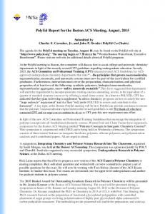
81st MEETING OF BRIDGE AND STRUCTURES STANDARDS COMMITTEE (February, 2012) Item No. 1033 continued…. 2.12.9.3 - Vertical Hold-Down Devices In zone IV and V, vertical hold-down devices shall be provided at all supports where resulting vertical force due to the maximum elastic horizontal and vertical seismic forces opposes and exceeds 50% of the dead load reaction. 2.12.9.3.1 - Where vertical force U, due to the combined effect of maximum elastic horizontal and vertical seismic forces, opposes and exceeds 50%, but is less than 100%, of the dead load reaction D, the vertical hold-down device shall be designed for a minimum net upward force of 10% of the downward dead load reaction that would be exerted if the span were simply supported. 2.12.9.3.2 - If the vertical force U, due to the combined effect of maximum horizontal and vertical seismic forces, opposes and exceeds 100% of the dead load reaction D, then the device shall be designed for a net upward force of 1.2(U-D); however, it shall not be less than 10% of the downward dead load reaction that would be exerted if the span were simply supported. 2.12.9.4-Horizontal Linkage Elements In case of Railway Bridges, Track and guard rail are likely to provide good resistance to sliding and overturning of spans. 2.12.9.4.1 - Reaction blocks (or seismic arrestors) when used as antidislodging elements shall be designed for seismic force equal to 1.5 times the elastic seismic coefficient multiplied by tributary weight of spans corresponding to that pier/abutment. 2.12.9.5 Minimum Seating Width Requirements The widths of seating W (in mm) at supports measured normal to the face of the abutment/pier/pedestal of bearings/restrained portion of superstructure from the closest end of the girder shall be following: (a) the value specified below: 300 + 1.5L + 6Hp for seismic zones II and III W= 500 + 2.5L + 10Hp for seismic zones IV and V where L = Length (in meters) of the superstructure to the adjacent expansion joint or to the end of superstructure. In case of bearings under suspended spans, it is sum of the lengths of the two adjacent portions of the superstructure. In case of single span bridges, it is equal to the length of the superstructure. For bearings at abutments, Hp is the average height (in meters) of all columns supporting the superstructure to the next expansion joint. It is equal to zero for single span bridges. For bearings at columns or piers, Hp is the height (in meters) of column or pier. For bearings under suspended spans, Hp is the average height (in meters) of the two adjacent columns or piers. Graphical representation of seating widths is shown in Fig.
55
81st MEETING OF BRIDGE AND STRUCTURES STANDARDS COMMITTEE (February, 2012) Item No. 1033 continued…. 2.12.9.6. Post earthquake Operation and Inspection The response of railway tracks and bridges to an earthquake would depend on distance from epicenter and nature of attenuation. The post earthquake train operations in the region shall be cautiously started. Detailed procedure for post earthquake operations and inspection is explained in Appendix – XXXI
Fig.: Minimum Width of Seating of Spans on Supports
56
81st MEETING OF BRIDGE AND STRUCTURES STANDARDS COMMITTEE (February, 2012) Item No. 1033 continued….
Appendix – (XXX) Ductile Detailing Specifications 1.
General The detailing rules given have been chosen with the intention that reliable plastic hinges should form at the top and bottom of each pier column, or at the bottom only of a single stem pier under horizontal loading and that the bridge should remain elastic between the hinges (Fig. A-1). The aim is to achieve a reliable ductile structure. Repair of plastic hinges is relatively easy. Design strategy to be used is based on assumption that the plastic response will occur in the substructure. However, in case of a wall type substructure, the nonlinear behaviour may occur in the foundationground system.
2.
Specification
2.1
Minimum grade of concrete should be M25 (fck = 25 MPa).
2.2
Steel reinforcement of grade Fe 415 (see IS 1786: 1985) or less only shall be used. However, high strength deformed steel bars of grades Fe 500, having elongation more than 14.5 percent and conforming to other requirements of IS 1786 : 1985 may also be used for the reinforcement.
3.
Layout (a) The use of circular column is preferred for better plastic hinge performance and ease of construction. (b)The bridge must be proportioned and detailed by the designer so that plastic hinges occur only at the controlled locations (e.g., pier column ends) and not in other uncontrolled places.
4.
Longitudinal Reinforcement The area of the longitudinal reinforcement shall not be less than 0.8 percent nor more than 6 percent, of the gross cross section area Ag. Splicing of flexural region is not permitted in the plastic hinge region. Lap shall not be located within a distance of 2 times the maximum column cross-sectional dimension from the end at which hinging can occur. The splices should be proportioned as a tension splice.
4.1
Curtailment of longitudinal reinforcement in piers due to reduction in seismic bending moment towards top.
4.2
The reduction of longitudinal reinforcement at mid-height in piers should not be carried out except in tall pier.
4.3
In case of high bridge piers such as of height equal to 30m or more, the reduction of reinforcement at mid height may be done. In such cases the following method should be adopted:
57
81st MEETING OF BRIDGE AND STRUCTURES STANDARDS COMMITTEE (February, 2012) Item No. 1033 continued…. (i) The curtailment of longitudinal reinforcement shall not be carried out in the section six times the least lateral column dimension from the location where plastic hinge is likely to occur. (ii) The interval between hoop ties is specified to be less than 150mm in a reinforcement position. The interval between hoop ties shall not change abruptly, the change must be gradual. 5.
Transverse Reinforcement The transverse reinforcement for circular columns shall consist of spiral or circular hoops. Continuity of these reinforcements should be provided by either (Fig. A -.2(a) or A-2.(b)): (a) Welding, where the minimum length of weld should be 12 bar diameter, and the minimum weld throat thickness should be 0.4 times the bar diameter. (b) Lapping, where the minimum length of lap should be 30 bar diameters and each end of the bar anchored with 135 hooks with a 10 diameter extension into the confined core. Splicing of the spiral reinforcement in the plastic hinge region should be avoided. In rectangular columns, rectangular hoops may be used. A rectangular hoop is a closed stirrup, having a 135 hook with a 10 diameter extension at each end that is embedded in the confined core (Figure A2.c). When hoop ties are joined in any place other than a corner the hoop ties shall overlap each other by a length 40 bar diameter of the reinforcing bar which makes the hoop ties with hooks as specified above. Joint portion of hoop ties for both circular and rectangular hoops should be staggered.
6.
Design of Plastic Hinge Regions
6.1
Seismic Design Force for Substructure Provisions given in this Appendix for the ductile detailing of RC members subjected to seismic forces shall be adopted for supporting components of the bridge. The design shear force at the critical section(s) of substructures shall be the lower of the following: (a) Maximum shear force that develops when (i) the substructure has maximum moment that it can sustain (i.e., the overstrength plastic moment capacity as per Clause 6.2) in single-column or single-pier type substructure. (ii) plastic moment hinges are formed in the substructure so as to form a collapse mechanism in multiple-column frame type or multiple-pier type substructures, in which the plastic moment
58
81st MEETING OF BRIDGE AND STRUCTURES STANDARDS COMMITTEE (February, 2012) Item No. 1033 continued…. capacity shall be the overstrength plastic moment capacity as per Clause 6.2. In a single-column type or pier type substructure, the critical section is at the bottom of the column or pier as shown in Figure A-1(a) and, in multi-column frame-type substructures or multi-pier substructures, the critical sections are at the bottom and/or top of the columns/piers as shown in Figure A-1(b). 6.2
Over strength Plastic Moment Capacity The over strength plastic moment capacity at a reinforced concrete section shall be taken as 1.3 times the ultimate moment capacity based on the usual partial safety factors recommended by relevant design codes for materials and loads, and on the actual dimensions of members and the actual reinforcement detailing adopted.
6.3
Special Confining Reinforcement: Special confining reinforcement shall be provided at the ends of pier columns where plastic hinge can occur. This transverse reinforcement should extend for a distance from the point of maximum moment over the plastic hinge region over a length l0. The length l0 shall not be less than, (a) 1.5 times the column diameter or 1.5 times the larger cross sectional dimension where yielding occurs (b) 1/6 of clear height of the column for frame pier (i.e when hinging can occur at both ends of the column) (c) 1/4 of clear height of the column for cantilever pier (i.e when hinging can occur at only one end of the column) (d) 600 mm
6.4
Spacing of Transverse Reinforcement The spacing of hoops used as special confining reinforcement shall not exceed (i) 1/5 times the least lateral dimension of the cross section of column, (ii) 6 times the diameter of the longitudinal bar, (iii) 150 mm The parallel legs of rectangular stirrups shall be spaced not more than 1/3 of the smallest dimension of the concrete core or more than 350 mm centre to centre. If the length of any side of the stirrups exceeds 350 mm, a cross tie shall be provided. Alternatively, overlapping stirrups may be provided within the column.
59
81st MEETING OF BRIDGE AND STRUCTURES STANDARDS COMMITTEE (February, 2012) Item No. 1033 continued…. 6.5
Amount of Transverse Steel to Be Provided
6.5.1 The area of cross section, Ash, of the bar forming circular hoops or spiral, to be used as special confining reinforcement, shall not be less than Ag f Ash 0.09SDk 1.0 ck Ac fy f or, Ash 0.024 SDk ck fy whichever is the greater
where Ash = area of cross-section of circular hoop S = pitch of spiral or spacing of hoops in mm Dk = Diameter of core measured to the outside of the spiral or hoops in mm fck = characteristic compressive strength of concrete fy = yield stress of steel (of circular hoops or spiral ) Ag = gross area of the column cross section Ac = Area of the concrete core =
4
Dk2
6.5.2 The total area of cross-section of the bar forming rectangular hoop and cross ties, Ash to be used as special confining reinforcement shall not be less than
Ag f Asw 0.24Sh 1.0 ck Ar fy Or, Asw 0.096Sh
f ck fy
where h= longer dimension of the rectangular confining hoop measured to its outer face Ar= Area of confined core concrete in the rectangular hoop measure to its outer side dimensions. Note: Crossties where used should be of the same diameter as the peripheral hoop bar and Ar shall be measured as the overall core area, regardless the hoop area. The hooks of crossties shall engage peripheral longitudinal bars.
60
81st MEETING OF BRIDGE AND STRUCTURES STANDARDS COMMITTEE (February, 2012) Item No. 1033 continued…. 6.5.3 Unsupported length of rectangular hoops shall not exceed 300mm. 6.5.4. For ductile detailing of hollow cross-section of pier special literature may be referred. Some of the provisions for hollow RC piers are: i) For hollow cylindrical piers, in the plastic hinge region, the ratio of internal diameter to thickness should not exceed 8.0. ii) For wall type hollow piers, in the plastic region, the ratio of clear width of the wall to thickness should not exceed 8.0. 7.
Design of Components between the Hinges Once the position of the plastic hinges has been determined and these regions detailed to ensure a ductile performance, the structure between the plastic hinges is designed considering the capacity of the plastic hinges. The intention here is: (i) To reliably protect the bridge against collapse so that it will be available for service after a major shaking. (ii) To localize structural damage to the plastic hinge regions where it can be controlled and repaired. The process of designing the structure between the plastic hinges is known as “capacity design”.
7.1
Column Shear and Transverse Reinforcement To avoid a brittle shear failure design shear force for pier shall be based on overstrength moment capacities of the plastic hinges and given by:
Vu
MO h
where
M O the sum of the overstrength moment capacities of the hinges resisting lateral loads, as detailed. In case of twin pier this would be the sum of the overstrength moment capacities at the top and bottom of the column. For single stem piers the overstrength moment capacity at the bottom only should be used. h = clear height of the column in the case of a column in double curvature; height to calculated point of contra-flexure in the case of a column in single curvature. Outside the hinge regions, the spacing of hoops shall not exceed half the least lateral dimension of the column, nor 300 mm. 8.
Design of Joints: Beam-column joints should be designed properly to resist the forces caused by axial loads, bending and shear forces in the joining members. Forces in the joint should be determined by considering a 61
81st MEETING OF BRIDGE AND STRUCTURES STANDARDS COMMITTEE (February, 2012) Item No. 1033 continued…. free body of the joint with the forces on the joint member boundaries properly represented. The joint shear strength should be entirely provided by transverse reinforcement. Where the joint is not confined adequately (i.e. where minimum pier and pile cap width is less than three column diameters) the special confinement requirement should be satisfied. 8.1
Ductility of all the joints in the structure may be ensured by offsetting the splices / couplers where the area of reinforcement provided is at least twice the required by analysis staggered 600 mm minimum.
8.2
The pier – foundation joint or the slab – pier joint (in case of integral slab – bridges ) must be checked for principal tensile stress in the concrete around the junction , following an appropriate prevailing method. The un-cracked joint may be designed by keeping the principal stresses in the joint region below direct tension strength of concrete. If the joint cannot be prevented from cracking, additional vertical stirrups may be added to the external concrete region around the column.
62
81st MEETING OF BRIDGE AND STRUCTURES STANDARDS COMMITTEE (February, 2012) Item No. 1033 continued…. The joint stresses may be assumed to disperse 45º around the column as per prevailing practices.
Earthquake Force
A
S u p e r s t r u c t u r e
C o l u m n
C o l u Potential Plastic m C Hinge Regions n a p
Pile Cap
Pil e
Earthquake Force
A Elevation Section AA (a) Single column or pier type substructures
Earthquake Force
A
C o l u m n s
C o l u m n
Potential Plastic Hinge Regions
C a p P i l e
A
P i l e s
S u p e r s t r u c t u r e
Earthquake Force
C a Elevation Section AA p (b) multi-column or frame type substructures Fig. A-1: Potential location of plastic hinges in substructures
63
81st MEETING OF BRIDGE AND STRUCTURES STANDARDS COMMITTEE (February, 2012) Item No. 1033 continued….
a) Welding in Circular hoops
(b) Lapping in circular hoops
(c)Rectangular hoops Fig. A-2: Transverse reinforcement in column
64
81st MEETING OF BRIDGE AND STRUCTURES STANDARDS COMMITTEE (February, 2012)
Item No. 1033 continued…. Appendix – (XXXI) Post Earthquake Operations and Inspections 1.0 - Post Earthquake Operations and Inspections The response of railway tracks and bridges to an earthquake would depend on distance from epicenter and nature of attenuation. The post earthquake train operations in the region shall be cautiously started. 1.1 - Operations After an earthquake is reported, the train dispatcher shall notify all the trains and engines within 150 km radius of the reporting area to run at restricted speed until magnitude and epicenter have been determined by proper authority. After determination of the magnitude and epicenter, response levels given in Table 1 and 2 will govern the operations. Table – 1 Specified Radius of Different Earthquake Earthquake Magnitude (Richter)
Response Level
Specified Radius
0- 4.9
I
5.0 – 5.9
II
80 km
III
160 km
II
240 km
III
*
II
*
6.0 – 6.9 7.0 or above
* As directed but not less than 6.0 – 6.9 Table –2 Details of Response Level Response Details level I
II
Resume maximum operation speed. The need for the continuation of inspections will be determined by proper authority responsible for maintenance of P.Way. All trains and engines will run at restricted speed within a specified radius of the epicenter until inspections have been made and appropriate speeds established by proper authority.
65
81st MEETING OF BRIDGE AND STRUCTURES STANDARDS COMMITTEE (February, 2012) Item No. 1033 continued….
III
All trains and engines within the specified radius of the epicenter must stop and may not proceed until proper inspections have been performed and appropriate speed restrictions established by proper authority. For earthquakes of Richter magnitude 7.0 or above, operations shall be directed by proper authority, but the radii shall not be less than that specified for earthquakes between 6.0 and 6.99.
1.2 - Post Earthquake Inspection The following list provides a general guideline for an inspection procedure: 1.2.1 - Track and Roadbed During the post earthquake inspection, following items shall be observed: o Line, surface and cross level irregularities caused by embankment slides or liquefaction o Track buckling or pull apart due to soil movement o Offset across fault rupture o Disturbed ballast o Cracks or slope failures in embankments o Slides and/or potential slides in cuts, including loose rocks that could fall in an aftershock o Scour due to tsunami in coastal area Potential for scour or ponding against embankment due to changes in water course 1.2.2 - Bridges Following an earthquake, inspectors may need to travel by rail between bridges. River bed may get flooded, hence, to quickly reach the bearings; alternate access routes shall be made. In steel bridges following shall be observed carefully: o o o o o o
Displaced or damaged bearings Stretched or broken anchor bolts Distress in viaduct tower Buckled columns or bracings Tension distress in main members or bracings Displaced substructure elements
66
81st MEETING OF BRIDGE AND STRUCTURES STANDARDS COMMITTEE (February, 2012)
Item No. 1033 continued…. Concrete bridge inspection shall include the following : o o o o
Displacement at bearings Displaced substructure elements Cracks in superstructure Cracks in substructure
Inspection team shall also look for items which may fall on track. At an overpass, attention shall be given to reduced span at bearings, damages to column and restrainer system. If there are adjacent buildings to railway track, then such buildings shall also be inspected to ensure if they can withstand aftershocks. Inspection team shall also look for damages to the powerlines passing over the track. 13.
Item No. 1008/79th/2010/CBS/Pathway Provision of Pathways on long girder bridge for inspection and maintenance. COMMITTEE‟S RECOMMENDATIONS: Following recommendations are made: (A) Indian Railway Schedule of dimension Item 15 (i) and (ii) is recommended for amendment as under: Maximum distance apart of trolley refuges: (i) On bridges with main spans of less than 50m = 50m (ii) On bridges with main spans of 50m or more pier
= A refuge over each
(B) A pathway of minimum 0.75m be provided on all major bridges. RDSO should develop GAD for provision of pathway. Zonal railways should send their practices and drawings on the subject for study and development of drawing. RAILWAY BOARD‟S ORDER: Railways to provide man refuges as per drawing provided by RDSO. PRESENT STATUS: Item may be closed. 14.
Item No. 1009/79th/2010/CBS/DCS Standard drawing of Precast RC Bridge Slabs of standard spans 0.61, 0.915, 1.22, 1.83 & 2.44m for 25t Loading-2008, (Concrete Grade M-25). COMMITTEE‟S RECOMMENDATIONS: i)
Provisional Drawing No. RDSO/B-10063 is approved.
ii)
RDSO should also issue drawings for severe and extreme environment condition for 0.61m, 0.915m, 1.22m, 1.83m and 2.44m spans only. 67
81st MEETING OF BRIDGE AND STRUCTURES STANDARDS COMMITTEE (February, 2012) Item No. 1033 continued…. RAILWAY BOARD ORDERS: Railway Board‟s orders are not required in terms of Board‟s letter No. 2005/CE-I/BR-II/8 dated 04-08-09. RDSO should issue the drawing expeditiously. PRESENT STATUS: 1. The work of design of RC bridge slabs of standards spans 0.61, 0.915, 1.22, 1.83 and 2.44m for severe environmental exposure condition has been completed and drawings have been uploaded on RDSO website. Zonal Railways have been advised vide letter No. CBS/DCS dated 05/07.10.2011. 2. The work of design of these slabs for extreme environmental exposure condition is in progress and design shall be issued shortly. 15.
Item No. 1010/79th/2010/CBS/DCS Standard drawing of Precast RC Bridge Slabs of standard spans 0.61, 0.915, 1.22, 1.83 & 2.44m for DFC Loading (32.5t Axle Load), (Concrete Grade M30). COMMITTEE‟S RECOMMENDATIONS: i)
RDSO Drawing No. RDSO/B-10062 is approved.
ii)
RDSO should issue drawings for the design of 0.61m, 0.915m, 1.22m, 1.83m and 2.44m slabs for extreme environment conditions also.
RAILWAY BOARD ORDERS: Railway Board‟s orders are not required in terms of Board‟s letter No. 2005/CE-I/BR-II/8 dated 04-08-09. RDSO should issue the drawing expeditiously. PRESENT STATUS: The standard design for moderate condition already issued. The standard design of precast RC Bridge slabs of standard spans 0.61, 0.915, 1.22, 1.83 and 2.44m for DFC loading and extreme environmental exposure condition is in progress and will be completed shortly. 16.
Item No. 1011/79th/2010/CBS/DPA Design of substructure i.e. Pier and Abutment suitable for span 6.1m precast PSC slab (2 units) conforming to 25t Loading-2008. COMMITTEE‟S RECOMMENDATIONS: i)
RDSO drawing No. RDSO/B-10337 and RDSO/B-10338 are approved.
ii)
RDSO should also issue drawing for reinforced concrete pier and abutment for 6.10m span pre-cast PSC slab (25t Loading-2008) for seismic Zone-V only taking open foundation and extreme soil conditions etc.
68
81st MEETING OF BRIDGE AND STRUCTURES STANDARDS COMMITTEE (February, 2012) Item No. 1033 continued…. RAILWAY BOARD ORDERS: Railway Board‟s orders are not required in terms of Board‟s letter No. 2005/CE-I/BR-II/8 dated 04-08-09. RDSO should issue the drawing expeditiously. PRESENT STATUS:
17.
i)
The provisional drawing No. RDSO/B-10257 of superstructure i.e. PSC slab (Pre-tensioned) for 6.1m span is under revision as per recommendations of 79th BSC vide item No.1016.
ii)
The work of design of substructure as per BSC recommendations would be taken up by RDSO in the year 2012-13.
Item No. 1012/79th/2010/CBS/DPA Design of substructure i.e. Pier and Abutment suitable for span 9.15m precast pre-tensioned PSC slab (3 units) conforming to 25t Loading-2008. COMMITTEE‟S RECOMMENDATIONS: i)
RDSO drawing approved.
No.
RDSO/B-10339
and
RDSO/B-10340
are
ii)
RDSO should also issue drawing for reinforced concrete pier and abutment for 9.15m pre-cast pre-tensioned PSC slab (3units) (25t Loading-2008) for seismic Zone-V only taking open foundation and extreme soil conditions etc.
RAILWAY BOARD ORDERS: Railway Board‟s orders are not required in terms of Board‟s letter No. 2005/CE-I/BR-II/8 dated 04-08-09. RDSO should issue the drawing expeditiously. PRESENT STATUS:
18.
i)
The provisional drawing No. RDSO/B-10263 of superstructure i.e. precast pre-tensioned PSC slab (3 units) for 9.15m span has been revised as per recommendations of 79 th BSC vide item No.1017. Accordingly, RDSO has issued revised provisional drawings No. RDSO/B-10339/R and RDSO/B-10340/R for mass concrete substructure i.e. Pier & Abutment respectively.
ii)
The design work of RCC substructure for seismic zone-V as recommended by BSC would be taken up by RDSO in the year 201213.
Item No. 1013/79th/2010/CBS/DPS Standard drawing of 3.05m PSC Pre-tensioned slab (2-unit) for 25t Loading2008. COMMITTEE‟S RECOMMENDATIONS: Drawing should be issued at the earliest.
69
81st MEETING OF BRIDGE AND STRUCTURES STANDARDS COMMITTEE (February, 2012) Item No. 1033 continued…. RAILWAY BOARD ORDERS: Railway Board‟s orders are not required in terms of Board‟s letter No. 2005/CE-I/BR-II/8 dated 04-08-09. RDSO should issue the drawing expeditiously. PRESENT STATUS: Drawing revised as per Committee Recommendation and revised drawing no. RDSO/B-10259/R issued to Zonal Railway vide letter no. CBS/DPS dated 25.11.11. 19.
Item No. 1014/79th/2010/CBS/DPS Standard drawing of 3.66m PSC Pre-tensioned slab (2-unit) for 25t Loading2008. COMMITTEE‟S RECOMMENDATIONS: Drawing should be issued at the earliest. RAILWAY BOARD ORDERS: Railway Board‟s orders are not required in terms of Board‟s letter No. 2005/CE-I/BR-II/8 dated 04-08-09. RDSO should issue the drawing expeditiously. PRESENT STATUS: Drawing revised for severe conditions as per Committee Recommendation and revised drawing no. RDSO/B-10260/R issued to Zonal Railway vide letter no. CBS/DPS dated 29.08.2011.
20.
Item No. 1015/79th/2010/CBS/DPS Standard drawing of 4.57m PSC Pre-tensioned slab (2-unit) for 25t Loading2008. COMMITTEE‟S RECOMMENDATIONS: Drawing should be issued at the earliest. RAILWAY BOARD ORDERS: Railway Board‟s orders are not required in terms of Board‟s letter No. 2005/CE-I/BR-II/8 dated 04-08-09. RDSO should issue the drawing expeditiously. PRESENT STATUS: Drawing revised for severe condition as per Committee Recommendation and revised drawing no. RDSO/B-10261/R issued to Zonal Railway vide letter no. CBS/DPS dated 01.08.2011.
70
81st MEETING OF BRIDGE AND STRUCTURES STANDARDS COMMITTEE (February, 2012) Item No. 1033 continued…. 21.
Item No. 1016/79th/2010/CBS/DPS Standard drawing of 6.1m PSC Pre-tensioned slab (2 unit) for 25t Loading2008. COMMITTEE‟S RECOMMENDATIONS: Drawing should be issued at the earliest. RAILWAY BOARD ORDERS: Railway Board‟s orders are not required in terms of Board‟s letter No. 2005/CE-I/BR-II/8 dated 04-08-09. RDSO should issue the drawing expeditiously. PRESENT STATUS: Design work is in progress for severe condition. Drawing will be issued shortly.
22.
Item No. 1017/79th/2010/CBS/DPS Standard drawings of 9.15m PSC Pre-tensioned slab (3 unit) for 25t Loading2008. COMMITTEE‟S RECOMMENDATIONS: Drawing should be issued incorporating the provision of additional lifting hook at the outside center of the ballast retainer. RAILWAY BOARD ORDERS: Railway Board‟s orders are not required in terms of Board‟s letter No. 2005/CE-I/BR-II/8 dated 04-08-09. RDSO should issue the drawing expeditiously. PRESENT STATUS: Drawing revised for severe condition as per Committee Recommendation and revised drawing no. RDSO/B-10263/R issued t o Zonal Railway vide letter no. CBS/DPS dated 22.9.2011.
23.
Item No. 1021/80th/2011/ CBS/DCP/1 Provision of Shut-off valves for pipe line crossings under railway track conveying inflammable substances like petroleum oil and gases etc. COMMITTEE‟S RECOMMENDATIONS: Case to be discussed with ONGC and GAIL and their view should be put-up in next BSC.
71
81st MEETING OF BRIDGE AND STRUCTURES STANDARDS COMMITTEE (February, 2012) Item No. 1033 continued…. RAILWAY BOARD ORDERS: Basically, ONGC and GAIL need to be consulted and their views obtained for deciding the issue. RDSO should take up the issue with ONGC and GAIL for obtaining their views on provision of shut off valves for pipeline crossing under Railway Track transporting inflammable substances like Petroleum Oil and Gases etc. The views of ONGC and GAIL be put up in next BSC and issue deliberated further. PRESENT STATUS: 1. The guidelines/codal provisions of following railroads vis-a-vis provisions of BS-105 were discussed during 80th BSC meeting: i) AREMA (American Railway Engineering and Maintenance-of-Way Association) Guidelines 2002. ii) Standards respecting Pipeline Crossing under Railways (Railways Association of Canada), June 21, 2000. iii) Metra Guidelines for utility Installations (Part-2 Pipelines: Flammable and Non-Flammable Materials), September, 2007. iv) Burlington Northern Santa Fe (BNSF) Railways Utility Accommodation Policy of April 16, 2004, Revised May 5, 2007. 2. Based on the above provisions, RDSO proposed the following amendment in Clause 5.5 of Report BS–105. “5.5 Accessible emergency shut off valves shall be installed within effective distance each side of the railway as mutually agreed to by the engineer and the pipeline company. These valves should be marked with sign for identification. Where pipelines are provided with automatic control stations at locations and within distances approved by the engineer, no additional valves shall be required. Valves shall not be located within the railway boundary.” 3. As per recommendations of 81st BSC and Railway Board‟s orders thereon, subject matter was discussed in detail with representatives of GAIL and Indian Oil Corporation (IOC) in April 2011. They were requested to provide extant instructions/industry practices regarding provisions of shut off valves. They informed that relevant ASME Codes are followed by them. The documents (ASME B31.4-2009: Pipeline Transportation System for liquid Hydrocarbons and other Liquids and ASME B31.8-2010: Gas Transmission and distribution Piping System) were accordingly procured by RDSO and studied. The relevant provisions of these documents are extracted below:
72
81st MEETING OF BRIDGE AND STRUCTURES STANDARDS COMMITTEE (February, 2012) Item No. 1033 continued…. A. ASME B31.8-2010: Gas Transmission and distribution Piping System Para 846 VALVES Para 846.1 Required spacing of Valves Para 846.1.1 Transmission Lines Onshore block valves shall be installed in new transmission pipelines at the time of construction for the purpose of isolating the pipelines for maintenance and for response to operating emergencies. When determining the placement of such valves for sectionalizing the pipelines, primary consideration shall be given to locations that provide continuous accessibility to the valves: (a) In determining the number and spacing of valves to be installed, the operator shall perform an assessment that gives consideration to factors such as (1) the amount of gas released due to repair and maintenance blow downs, leaks, or ruptures (2) the time to blow down an isolated section (3) the impact in the area of gas release (e.g., nuisance and any hazard resulting from prolonged blow downs) (4) continuity of service (5) operating and maintenance flexibility of the system (6) future development in the vicinity of the pipeline (7) significant conditions that may adversely affect the operation and security of the line (b) In lieu of (a) above, the following maximum spacing between valves shall be used:(1) 20 miles (32 km) in areas of predominantly Location Class 1 (2) 15 miles (24 km) in areas of predominantly Location Class 2 (3) 10 miles (16 km) in areas of predominantly Location Class 3 (4) 5 miles (8 km) in areas of predominantly Location Class 4 The spacing defined above may be adjusted to permit a valve to be installed in a location that is more accessible.
73
81st MEETING OF BRIDGE AND STRUCTURES STANDARDS COMMITTEE (February, 2012) Item No. 1033 continued…. {Para 840.2.2 Location class for design and construction (a) Location Class1. A Location Class1 is any 1-mile (1.6-km) section that has 10 or fewer buildings intended for human occupancy. A Location class1 is intended to reflect areas such as wasteland, deserts, mountains, grazing land, farmland, and sparsely populated areas. (b) Location Class2. A Location Class2 is any 1-mile (1.6-km) section that has more than 10 but fewer than 46 buildings intended for human occupancy. A Location class2 is intended to reflect area where the degree of population is intermediate between Location Class1 and Location Class3, such as fringe areas around cities and towns, industrial area, ranch or country estates, etc. (c) Location Class3. A Location Class3 is any 1- mile (1.6-km) section that has 46 or more buildings intended for human occupancy except when a Location Class4 prevails. A Location Class 3 is intended to reflect areas such as suburban housing developments, shopping centers, residential areas, industrial areas and other populated areas not meeting Location Class4 requirements. (d) Location Class4. Location Class4 includes areas where multistory buildings are prevalent, where traffic is heavy or dense, and where there may be numerous other utilities underground. Multistory means four or more floors above ground including the first or ground floor. The depth of basements or number of basement floor is immaterial.} Para 846.1.2 Distribution Mains Valves on distribution mains, whether for operating or emergency purpose, shall be spaced as follows: (a) High-Pressure Distribution Systems. Valves shall be installed in highpressure distribution systems in accessible locations to reduce the time to shut down a section of main in an emergency. In determining the spacing of the valves, consideration should be given to the operating pressure and size of the mains and local physical conditions as well as the number and type of consumers that might be affected by a shutdown. (b) Low-Pressure Distribution Systems. Valves may be used on low-pressure distribution system but are not required except as specified in para. 846.2.2(a).
74
81st MEETING OF BRIDGE AND STRUCTURES STANDARDS COMMITTEE (February, 2012) Item No. 1033 continued…. Para 846.2 Location of valves Para 846.2.1 Transmission Valves (a) Sectionalizing block valves shall be accessible and protected from damage and tampering. If a blowdown valve is involved, it shall be located where the gas can be blown to the atmosphere without undue hazard. (b) Sectionalizing valves may be installed above ground, in a vault, or buried. In all installation an operating device to open or close the valve shall be readily accessible to authorized persons. All valves shall be suitably supported to prevent settlement or movement of the attached piping. (c) Blowdown valve shall be provided so that each section of pipeline between mainline valves can be blowdown. The size and capacity of the connections for blowing down the line shall be such that under emergency conditions the sections of line can be blown down as rapidly as practicable. (d) This Code does not require the use of automatic valves nor does the Code imply that the use of automatic valves presently developed will provide full protection to a piping system. There use and installation shall be at the direction of the operating company. Para 846.2.2 Distribution System Valves (a) A valve shall be installed on the inlet piping of each regulator station controlling the flow or pressure of gas in a distribution system. The distance between the valve and regulator or regulators shall be sufficient to permit the operation of the valve during the emergency, such as a large gas leak or a fire in the station. (b) Valves on distribution mains, whether for operating or emergency purposes, shall be located in a manner that will provide ready access and facilitate their operation during an emergency. Whether a valve is installed in a buried box or enclosure, only ready access to the operating stem or mechanism is implied. The box or enclosure shall be installed in a manner to avoid transmitting external loads to the main. B. ASME B31.4-2009 Pipeline Transportation Hydrocarbons and other Liquids
System
for
liquid
Para 434.15 Block and Isolating Valves Para 434.15.1 General (a) Block and isolating valves shall be installed for limiting hazard and damage from accidental discharge and for facilitating maintenance of the piping system. 75
81st MEETING OF BRIDGE AND STRUCTURES STANDARDS COMMITTEE (February, 2012) (b) Item No. 1033 continued…. (c) Valves shall be at accessible locations, protected from damage and tempering and suitably supported to prevent differential settlement or movement of the attached piping. Where an operating device to open or close the valve is provided, it shall be protected and accessible only to authorized persons. (d) Submerged valves on pipelines shall be marked or spotted by survey techniques to facilitate quick location when operation is required. Para 434.15.2 Mainline Valves (a) Mainline block valves shall be installed on the upstream side of major river crossings and public water supply reservoirs. Either a block or check valves shall be installed on the downstream side of major river crossings and public water supply reservoirs. (b) A mainline block valve shall be installed at mainline pump stations, and a block or check valve (where applicable to minimize pipeline backflow) shall be installed at other locations appropriate for the terrain features. In industrial, commercial, and residential areas where construction activities pose a particular risk of external damage to the pipeline, provisions shall be made for the appropriate spacing and location of mainline valves consistent with the type of liquids being transported. (c) A remotely operated mainline block valve shall be provided at remotely controlled pipelines facilities to isolate segments of the pipeline. (d) On piping systems transporting LPG or liquid anhydrous ammonia, check valves shall be installed were applicable with each block valve to provide automatic blockage of reverse flow in the piping system. (e) In order to facilitate operational control, limit the duration of an outage, and expedite repairs, mainline block valves shall be installed at 7.5 mile (12km) maximum spacing on piping systems transporting LPG or liquid anhydrous ammonia in industrial, commercial, and residential areas. Para 434.15.3 Pump Station, Tank Farm, and Terminal Valves (a) Valves shall be installed on the suction and discharge of pump stations whereby the pump station can be isolated from the pipeline. (b) Valves shall be installed on lines entraining or laving tank farms or terminals at convenient locations whereby the tank farm or terminal may be isolate from other facilities such as pipeline, manifolds, or pump stations. It can be seen from the above that:(1) Maximum distance between valves should be controlled in order to limit the hazard in case of any eventually. 76
81st MEETING OF BRIDGE AND STRUCTURES STANDARDS COMMITTEE (February, 2012) 2) Item No. 1033 continued….
(1) In heavy traffic or where underground utilities are permitted, maximum spacing of valves carrying gas should not be more than 8km. Railway Operations can be considered to fall in such location Class (i.e. Location Class4). (2) In case of pipelines carrying liquid hydrocarbons, the maximum distance between valves is 12Km. (3) Further block valves have been mandated on upstream side and check valves on the downstream side of major river crossings. Railway line carrying multiple tracks can be considered to be similar to such scenario. 4. 24.
In view of above, BSC may deliberate and decide.
Item No. 1022/80th/2011/ CBS/IRBM Modification in para 1104 of IRBM on account of Abolition of THOD System. COMMITTEE‟S RECOMMENDATIONS: Following modifications should be done in IRBM: (i)
Para 714(2) Para 2Word THOD to be replaced by CBE.
(ii)
Para 714(2) Para 4 & Para 1004(5), 1005(3)Word THOD to be deleted and para should be modified. Scrutiny of minor bridge registers can be done at divisional level except where some bridges are specifically referred to CBE. Major bridge register should be scrutinized by Dy.CE/Br./HQ at HQ level and put up to CBE.
(iii)
Para 1004(2)Word THOD should be replaced by CBE.
(iv)
Para 1004In Heading word THOD to be deleted.
(v)
Para 1006(2)Word “Through the THOD” to be deleted.
RAILWAY BOARD ORDERS: Orders will be issued separately. PRESENT STATUS: Advance correction slip no. 24 to Indian Railways Bridge Manual has ben issued in this regard vide Railway Board‟s letter no. 2010/CEI/BR/BSC/Seminar/1 dated 14-09-2011.
77
81st MEETING OF BRIDGE AND STRUCTURES STANDARDS COMMITTEE (February, 2012) Item No. 1033 continued…. 25.
Item No. 1024/80th/2011/ CBS/DFP Inclusion of provision of HSFG Bolt in IRS Steel Bridge Code. COMMITTEE‟S RECOMMENDATIONS: 1.
It may be adopted as alternative connections in railway bridge girders.
2.
The HSFG Bolts can be used in ROBs.
RAILWAY BOARD ORDERS: 1.
Based on recommendations of 59th BSC, Limited trials of HSFG Bolts as under were approved by Railway Boards: (i) Eastern and Central Railways may carry out trials of HSFG Bolts in splice joints on 18.3 meter span girders. (ii) All Railways may use HSFG Bolts as a trial measure in structures such as gantry girders etc. However performance reports of above trials were neither brought on record by RDSO nor deliberated in 80th BSC which had again discussed the subject of use of HSFG Bolts. Performance report of above trials be discussed in next BSC.
2.
BSC has not deliberated/ recommended about the specifications for HSFG Bolts for use on Railway Bridges/Structures.
PRESENT STATUS: 1.
No performance report on trials of HSFG bolts on Eastern and Central Railways for 18.3m span or from any railway on gantry girders etc. has been received.
2.
The detailed specifications in the form of new para 7.12 to be introduced in IRS Steel Bridge Code covering HSFG bolts for use on Railway Bridges/Structures are enclosed. Further corrections will be required in IRS B1-2001 and Indian Railways Bridge Manual once the HSFG bolt design is decided.
Committee may deliberate and give recommendations. Correction Slip to be incorporated in IRS Steel Bridge Code New Para 7.12 may be added as follows: 7.12 High Strength Friction Grip (HSFG) Bolts – High Strength Friction Grip (HSFG) bolts, when provided shall conform to IS:4000 (High Strength Bolts in Steel Structures – Code of Practice) with the following over-riding clauses: 7.12.1 IS:4000 shall be used in conformation with IRS Codes. Provisions not covered in this standard shall be conforming to IRS Codes. 7.12.2 Bearing type joints shall not be provided in bridges with HSFG Bolts. 7.12.3 Short/ long slotted holes shall not be allowed. 7.12.4 Oversize holes shall not exceed 1.25 d or d + 4 mm.
78
81st MEETING OF BRIDGE AND STRUCTURES STANDARDS COMMITTEE (February, 2012) Item No. 1033 continued…. 7.12.5 The fatigue category for HSFG bolt connections shall be same as the one for butt welds without stop/start positions. 7.12.6 In existing structures, HSFG bolts shall not be used to directly replace rivets unless it can be ensured that adequate slip factor is available. Commentary: 7.12.1
IS:4000 shall be used in conformation with IRS Codes. Provisions not covered in this standard shall be conforming to IRS Codes.
The IS:4000 code has all the provisions required for design and use of HSFG bolts. It compares well with international codes which are applicable to the railways. Hence the same has been followed for Indian Railways as well. For any issue where IS:800 has been specified to be used in IS:4000, IRS Codes shall be used as the provisions therein are as per railway requirements.
7.12.2
Bearing type joints IS:4000 provides for two types of joints, viz, Bearing shall not be provided type(Clause 5.3) and friction type(Clause 5.4). The in bridges. bearing type joint develops strength after minor slip and clause 5.3.1 provides for use of friction type joint where slip is not acceptable. On Railway bridges, the bearing type joints reduce the fatigue life of structures whereas the friction type joints have a better fatigue performance.
7.12.3
Short/ long slotted Clause 6.3.1 and 6.3.2 provide for slotted holes and holes shall not be oversize holes for HSFG bolts. The slotted holes are allowed. not required in the railway applications and in friction type joints the slots cannot be used for expansion/ contraction of the structures. Therefore, the slotted holes are not allowed in the railway bridges.
7.12.4
Oversize holes shall The limit for oversize holes given in clause 6.3.1(a) is not exceed 1.25 d or d 1.25 d or d + 8 mm. For railway application, the + 4 mm. oversize holes might be encountered when the HSFG bolts are used in the existing structures for replacement of rivets, etc. However, the value of d+8 mm is on higher side and might affect the performance of the joint due to 4 mm annular space all round, which has to be taken care of by hardened washer (clause 6.3.2(b)), hence the same is restricted to d+4 mm only (maximum annular space 2 mm all round).
79
81st MEETING OF BRIDGE AND STRUCTURES STANDARDS COMMITTEE (February, 2012) Item No. 1033 continued…. 7.12.5
In existing structures, HSFG bolts shall not be used to directly replace rivets unless it can be ensured that adequate slip factor is available.
Replacement of rivets by HSFG bolts can increase the fatigue life of the existing structures but the HSFG bolts require minimum 0.30 slip factor so as to be adequate for replacement of the existing rivets on one-to-one basis without going into detailed computations. The contact surfaces of the members in which the rivets are being replaced can be painted/rusted etc depending on the age of structure and the fabrication practices. Therefore, examination of the available slip factor is required before the decision to replace the rivets with HSFG bolts is taken. If the members joined are thinner or in case of multiple plies, the HSFG bolts can replace the rivets with lesser slip factor too. In case the slip factor is not adequate, the reaming of holes for next higher size bolts and/or extra bolts might be required.
7.12.6
The fatigue category for HSFG bolt connections shall be same as the one for butt welds without stop/start positions.
HSFG bolts transfer the loads through friction and the effect of stress concentration in holes on fatigue life is not there. Also, the clamping of the members with the bolts ensures transfer of loads more axially through the joints and the members as compared to the ordinary riveted/ bolted connections.
Corrections Required in “IRS Specification For Fabrication And Erection Of Steel Girder Bridges And Locomotive Turn-Tables (Fabrication Specification) Serial No. B1-2001” subsequently. 1. The HSFG bolts shall be used on railway bridges preferably with “Direct Tension Indicating” device. In case HSFG bolts are used without “Direct Tension Indicating” device, the agency installing the bolts has to get at least 20% of the installed bolts checked for correct tightness as per procedure given in Annex D after 6 months of train operations or 1 year of installation, whichever is earlier. 2. Painting during initial installation: In case of HSFG bolts with “Direct Tension Indicating” device, the final coat in field applied on complete structure may be applied on HSFG bolts also. In case part turn method of tensioning is used without “Direct Tension Indicating” device, the HSFG bolts shall not be painted and the permanent location marks made on the bolts shall be visible after 1 year of installation.
80
81st MEETING OF BRIDGE AND STRUCTURES STANDARDS COMMITTEE (February, 2012)
Item No. 1033 continued…. Corrections Required in “Indian Railways Bridge Manual” subsequently 1. The inspection of HSFG bolts shall be done visually. Where the looseness of bolts is seen by rust appearing beneath the bolt head/washer/nut etc or marks left by water or apparent relative movement between the steel parts joined by the HSFG bolts, the bolts shall be checked using torque wrench by procedure given in Annex D of IS:4000. 2. Painting in service: After one year of installation, the HSFG bolts shall be painted as per frequency/ scheme laid down for the steel girders. 26.
Item No. 1025/80th/2011/ CBS/DFOB Standard Drawings for FOB‟s. COMMITTEE‟S RECOMMENDATIONS: 1.
RDSO should issue standard design with triangulated girder.
2.
Standard design should be for 2, 3 & 4 track crossing.
3.
Standard design should be for 3.0m & 6.0m width..
RAILWAY BOARD ORDERS: BSC‟s Recommendations approved. PRESENT STATUS: The design of 6m vide and 3 track crossing is ready and being up loaded. Other drawing are also in progress. The salient features of 6m vide 3 track crossing are as under: The span of FOB is 25.2m considering 5.485m distance clear from the end as per item no. 7 (b) of Chapter-II of SOD (B.G.)-2004 3 tracks with track center as 5.3m and track center to platform coping distance is 1.68m. This drawing can be used for span 20m to 25m as per site conditions. The FOB is 6m vide with 4 girders (over all width 6.25m) and 3m high clear roof top. The width of stair cases are 4m and over all width 4.8m. 27.
Item No. 1026/80th/2011/ CBS/C-Spl/99 & CBS/CODES/A&C Coatings for Concrete structures. COMMITTEE‟S RECOMMENDATIONS: 1.
Western, Central and Southern Railways should send their feedback to RDSO on experience/performance of coating provided to concrete structures on their Railways.
2.
The feedback on experience/ performance of the coating should be presented in next BSC.
RAILWAY BOARD ORDERS: BSC‟s Recommendations approved.
81
81st MEETING OF BRIDGE AND STRUCTURES STANDARDS COMMITTEE (February, 2012) Item No. 1033 continued…. PRESENT STATUS: Western, Central and Southern Railways were requested to give the feedback to RDSO on experience/performance of coating to concrete structures on their Railways vide RDSO No. CBS/C-80/Coating dated 10.06.2011 and subsequent reminder dated 3.12.2011. No reply has yet been received. **********
82