aggregated multicast with bi-directional shared tree (AM w/BST). Some representative results are shown below. In the set of experiments for BST vs AM w/BST, ...
1
Aggregated Multicast—A Comparative Study Jun-Hong Cui, Jinkyu Kim Dario Maggiorini, Khaled Boussetta and Mario Gerla Computer Science Department, University of California, Los Angeles, CA 90095 {jcui,jinkyu,dario,boukha,gerla}@cs.ucla.edu
Abstract— Though IP multicast is resource ef£cient in delivering data to a group of members simultaneously, it suffers from scalability problem with the number of concurrently active multicast groups because it requires a router to keep forwarding state for every multicast tree passing through it. To solve this state scalability problem, we proposed a scheme, called aggregated multicast. The key idea is that multiple groups are forced to share a single delivery tree. In our earlier work, we introduced the basic concept of aggregated multicast and presented some initial results to show that multicast state can be reduced. In this paper, we develop a more quantitative assessment of the cost/bene£t trade-offs. We propose an algorithm to assign multicast groups to delivery trees with controllable cost and introduce metrics to measure multicast state and tree management overhead for multicast schemes. We then compare aggregated multicast with conventional multicast schemes, such as source speci£c tree scheme and shared tree scheme. Our extensive simulations show that aggregated multicast can achieve signi£cant routing state and tree management overhead reduction while containing the expense of extra resources (bandwidth waste and tunnelling overhead). We conclude that aggregated multicast is a very cost-effective and promising direction for scalable transit domain multicast provisioning.
I. I NTRODUCTION IP Multicast has been a very hot area of research, development and testing for more than one decade since Stephen Deering established the IP multicast model in 1988 [10]. However, IP multicast is still far from being widely deployed in the Internet. Among the issues which delay the deployment, state scalability is one of the most critical ones. IP multicast utilizes a tree delivery structure on which data packets are duplicated only at fork nodes and are forwarded only once over each link. By doing so IP multicast can scale well to support very large multicast groups. However, a tree delivery structure requires all tree nodes to maintain per-group (or even per-group/source) forwarding information, which increases linearly with the number of groups. Growing number of forwarding state entries means more memory requirement and slower forwarding process since every packet forwarding action involves an address look-up. Thus, multicast scales well to the number of members within a single multicast group, but it suffers from scalability problems when the number of simultaneously active multicast groups is very large. The forwarding-state scalability problem has prompted some recent research in forwarding state reduction. Some This material is based upon work supported by the National Science Foundation under Grant No. 9805436, and CISCO/CORE fund No. 9910060
architectures aim to completely eliminate multicast state at routers [16, 7, 22] using application level multicast, which pushes the complexity to the end-points. Some schemes attempt to reduce forwarding state at non-branched routers [26, 24, 8], while some other schemes try to achieve state reduction by forwarding-state aggregation [23, 25]. Thaler and Handley analyze the aggregatability of forwarding state in [25] using an input/output £lter model. Radoslavov et al. propose algorithms to aggregate forwarding state and study the bandwidth-memory tradeoff with simulations in [23]. However, this state aggregation technique attempts to aggregate routing state after the distribution trees have been established, and it tends to change the state format maintained in routers, which is generally not deserved by many service providers [9]. Furthermore, the state aggregatability of this technique heavily depends on multicast address allocation. To improve multicast state scalability, we proposed a novel scheme to reduce multicast state, which we call aggregated multicast. In this scheme, multiple multicast groups are forced to share one distribution tree, which we call an aggregated tree. This way, the number of trees in the network may be signi£cantly reduced. Consequently, forwarding state is also reduced: core routers only need to keep state per aggregated tree instead of per group. The trade-off is that this approach may waste extra bandwidth to deliver multicast data to non-group-member nodes. In our earlier work [14], we introduced the basic concept of aggregated multicast, and presented some initial results to show that multicast state can be reduced through intergroup tree sharing. However, a thorough performance evaluation of aggregated multicast is needed: what level of the gain does aggregated multicast offer over conventional multicast schemes? In this paper, we propose an algorithm to assign multicast groups to delivery trees with controllable cost and introduce metrics to measure multicast state and tree management overhead for multicast schemes. We then compare aggregated multicast with conventional multicast schemes, such as source speci£c tree scheme and shared tree scheme. Our extensive simulations show that aggregated multicast can achieve signi£cant state and tree management overhead reduction while at reasonable expense (bandwidth waste and tunnelling overhead). The rest of this paper is organized as follows. Section II gives some background on IP multicast and reviews some
mains. A border router capable of multicast communicates with its peer(s) in other domain(s) via inter-domain multicast protocols and routers in its own via intra-domain protocols, and forward multicast packets across the domain boundary. Currently there are two prominent interdomain multicast protocol suits: MBGP/PIM-SM/MSDP and MASC/BGMP [2, 19]. MBGP/PIM-SM/MSDP is a short-term solution, where MBGP to advertise multicast routes among domains, PIM-SM to build trees for members in different domains, and MSDP to connect RPs across domains. In the long-term solution MASC/BGMP, BGMP builds bi-directional shared trees across domains with a single root, and MASC is employed to solve the problem of multicast address collisions.
related work. Section III introduces a classi£cation of multicast schemes. Section II reviews the concept of aggregated multicast and presents an algorithm for group-tree matching. Section V then discusses the implementation issues for different multicast schemes and de£nes metrics to measure multicast state and tree management overhead, and Section VI provides an extensive simulation study of different multicast schemes. Finally Section VII summarizes the contributions of our work. II. BACKGROUND AND R ELATED W ORK A. Routing Architecture of Internet Multicast In the current IP multicast architecture, a host joins a multicast group by communicating with its designated router via Internet Group Membership Protocol (IGMP [6]) (by sending a membership report or answering a query from the router). IP multicast utilizes a tree structure to deliver multicast packets for a group. A tree consists of designated routers which have group member(s) in their subnets and other intermediate routers which help transport multicast traf£c. Multicast routing protocols determine how a multicast tree is formed. In this paper, a router in the delivery tree is called an in-tree router, and a designated router which has group participant host(s) in its subnet is called a (group) member router, and we are only concerned with multicast communication at the router level. To determine how to forward multicast packets received, a router maintains forwarding-state information for groups in which it is an in-tree router, though it may not be a member router. Depending on the routing protocol, forwarding-state information may have entries per group or per group/source. Multicast routing protocols determine how forwarding state is obtained and maintained. In MOSPF [20], routers within a domain exchange group membership information with each other. Each router computes a source-based multicast tree from which it obtains forwarding state that consists of (group/source, expected ininterface, out-interface(s)) information. DVMRP [21] or PIM-DM [11] builds per-source tree with a “¤ood-andprune” mechanism: a router ¤oods data to all outgoing links, unless “prune” state exists denoting downstream hosts are not interested. In CBT [4] or PIM-SM [12], a group member sends an explicit join request towards a core router or a rendezvous point (RP). The request is forwarded and processed by intermediate routers and the corresponding forwarding state is installed at each router. The Internet consists of numerous Autonomous Systems (AS) or domains. Domains may be connected as service provider/customers in a hierarchical manner or connected as peering neighbors, or both. Normally a domain is controlled by a single entity and can run an intra-domain multicast routing protocol of its choice. An inter-domain multicast routing protocol is deployed at border routers of a domain to construct multicast trees connecting to other do-
B. Other Related Work Besides state aggregation approach [23, 25], some other work also attempts to reduce or eliminate multicast state. Xcast [5] proposes to code a set of destinations’ addresses in a multicast packet so a router doesn’t need to maintain state information for the group. It aims to be an alternative for IP multicast for very small groups or for Inter-domain multicast. It doesn’t require a router to maintain multicast state but requires more processing of data packets at each router. Alternatively, in Yoid [16] and End-System Multicast [7], a self-organizing tree (and/or mesh) among group members is constructed to provide multi-point communications among them without network-layer multicast support. In this approach, native multicast may only be used within a limited scope [16] (e.g. at LAN level), while unicast is used pervasively among members. Because only members are involved in replicating and forwarding multicast packets, it is transparent to routers. Yoid and EndSystem Multicast might be good alternatives for smallscale multicast applications; however, it is dif£cult for them to scale up to support large-scale multicast applications like Internet TV that can have millions of group members since these protocols need to discover and maintain all or most group members. ALMI [22] is another application level multicast infrastructure. It uses a centralized algorithm to compute a minimum spanning tree rooted at a designated controller, and then disseminate routing tables to all members. This centralized nature limits the size of groups, as makes ALMI only suitable for applications with very small number of members. Another type of approach attempts to eliminate multicast forwarding state at non-branching routers (i.e. routers that forward multicast packets received for a group to only one out-going interface) [26, 24, 8]. Tian and Neufeld [26] propose to dynamically establish tunnels over nonbranching links (thus non-branching routers in between do not need state for that group). REUNITE [24] by Stoica et al. essentially proposes an alternative to IP multicast, in which a multicast group is identi£ed by a tu2
ple of root node IP address and a port number. Multicast state is installed at branching nodes only and packet forwarding is based on unicast in between. Multicast state is set up through explicit JOIN messages from members (grafting new members to some branching routers or root when necessary) and TREE messages from root (creating routes from root to members when necessary). [8] modi£es the REUNITE approach by adopting source-speci£c channel abstraction to simplify multicast address allocation [18]. And by introducing FUSION messages (used to merge routes when necessary), it improves the stability of tree structures caused by member dynamics and provides potential lower cost trees than REUNITE. It should be noted that all these no-branching-router dedicated approaches have a basic assumption: there are a large number of sparse groups in networks.
Domain E
Domain A
E1
B1
A2 Ab
A4
Domain B
Aa
Tunnel
A3
A1 X1
C1 Y1
Domain X
D1
Domain C
Domain Y
Customer networks, domain D
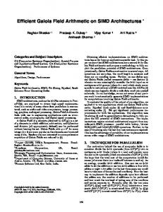
Fig. 2. A cross-domain multicast tree with nodes: D1, A1, Aa, Ab, A2, B1, A3, C1, covering group G0 (D1, B1, C1).
gregated multicast raises tree-sharing to an even higher level—inter-group tree sharing, where multiple multicast groups are forced to share one aggregated tree. An aggregated tree can be either a source speci£c tree or a shared tree, while a shared tree can be either unidirectional or bidirectional. We will review the basic concept of aggregated multicast and discuss some related issues in the following section.
III. A C LASSIFICATION OF M ULTICAST S CHEMES According to the type of delivery tree, we classify the existing intra-domain multicast routing protocols into two categories (In this paper, we only consider intra-domain multicasting, since aggregated multicast is an approach mainly designed for single domains): in the £rst category, protocols construct source speci£c tree, and in the second category, protocols utilize shared tree. For the convenience of discussion, we call the former category as source speci£c tree scheme, and the latter one as shared tree scheme. According to this classi£cation, we can say, DVMRP [21], PIM-DM [11], and MOSPF [20] belong to source speci£c tree scheme category, while CBT [3], PIMSM [13], and BIDIR-PIM [17] are basically shared tree schemes (of course, PIM-SM can also activate source speci£c tree when needed). Source speci£c tree schemes construct a separate delivery tree for each source. Namely, each source of a group utilizes its own tree to deliver data to the receivers in the group. Shared tree schemes instead construct trees based on per-group and all the sources of a group use the same tree to deliver data to the receivers. In other words, multiple sources of the same group share a single delivery tree. Shared tree can be unidirectional or bi-directional. PIM-SM is a unidirectional shared tree scheme. CBT and BIDIR-PIM are bi-directional shared tree schemes. Fig. 1 shows the different types of trees for the same group G with sources (S1, S2) and receivers (R1, R2). For source speci£c tree schemes, two trees are set up for group G. For the unidirectional shared tree scheme, one tree is set up. Each source needs to unicast packets to the rendezvous point (RP) or build source speci£c state on all nodes along the path between the source and the RP. For the last type of schemes, only one bi-directional tree will work. A source can unicast packet to the nearest on-tree node instead of RP. And each on-tree node can deliver packets along the bi-directional tree. Compared with conventional multicast schemes, ag-
IV. AGGREGATED M ULTICAST A. Concept of Aggregated Multicast Aggregated multicast [14] is proposed to reduce multicast state, and it is targeted to intra-domain multicast provisioning. The key idea is that, instead of constructing a tree for each individual multicast group in the core network (backbone), multiple multicast groups are forced to share a single delivery tree. Fig. 2 illustrates a hierarchical inter-domain network peering. Domain A is a regional or national ISP’s backbone network, and domain D, X, and Y are customer networks of domain A at a certain location (say, Los Angeles), and domain E is a customer network of domain A in another location (say, Seattle). Domain B and C can be other customer networks (say, in Boston) or some other ISP’s networks that peer with A. A multicast session originates at domain D and has members in domain B and C. Routers D1, A1, A2, A3, B1 and C1 form the multicast tree at the inter-domain level while A1, A2, A3, Aa and Ab form an intra-domain sub-tree within domain A (there may be other routers involved in domain B and C). Consider a second multicast session that originates at domain D and also has members in domain B and C. For this session, a sub-tree with exactly the same set of nodes will be established to carry its traf£c within domain A. Now if there is a third multicast session that originates at domain X and it also has members in domain B and C, then router X1 instead of D1 will be involved, but the sub-tree within domain A still involves the same set of nodes: A1, A2, A3, Aa, and Ab. To facilitate our discussions, we make the following def3
R1
Multicast S1 Multicast S2
R2
Unicast Multicast
R1
R2
RP
S1
S1
S2 (a) Source Specific Tree
R1
R2
R1
RP
S1
S2 (b) Unidirectional Shared Tree
R2
RP
S2
S1
S2
(d) Packet of S1 delivering on Bi-directional Shared Tree
(c) Bi-directional Shared Tree
Fig. 1. Different types of trees for the same group G with sources (S1, S2) and receivers (R1, R2).
initions. For a group G, we call terminal nodes the nodes where traf£c enters or leaves a domain, A1, A2, and A3 in our example. We call transit nodes the tree nodes that are internal to the domain, such as Aa and Ab in our example. In conventional IP multicast, all the nodes in the above example that are involved within domain A must maintain separate state for each of the three groups individually though their multicast trees are actually of the same “shape”. Alternatively, in the aggregated multicast, we can setup a pre-de£ned tree (or establish a tree on demand) that covers nodes A1, A2 and A3 using a single multicast group address (within domain A). This tree is called an aggregated tree and it is shared by more than one multicast groups (three groups in the above example). We say an aggregated tree T covers a group G if all terminal nodes for G are member nodes of T . Data from a speci£c group is encapsulated at the incoming terminal node using the address of the aggregated tree. It is then distributed over the aggregated tree and decapsulated at exiting terminal nodes to be further delivered to neighboring networks. This way, transit router Aa and Ab only need to maintain a single forwarding entry for the aggregated tree regardless how many groups are sharing it. Thus, aggregated multicast can reduce the required multicast state. Transit nodes don’t need to maintain state for individual groups; instead, they only maintain forwarding state for a smaller number of aggregated trees. The management overhead for the distribution trees is also reduced. First, there are fewer trees that exchange refresh messages. Second, tree maintenance can be a much less frequent process than in conventional multicast, since an aggregated
tree has a longer life span. This is an unique advantage compared with other state reduction schemes, such as [26], [23], [25], [24], and [8], etc. B. Group-Tree Matching in Aggregated Multicast Aggregated multicast achieves state reduction through inter-group tree sharing—multiple groups share a single aggregated tree. When a group is started, an aggregated tree should be assigned to the group following some rules. If a dense set of aggregated trees is pre-de£ned, things will be easy: just choose the tree with minimum cost which can cover the group. While in the dynamic case (aggregated tree are established on demand), a more elaborate grouptree matching algorithm is needed. When we try to match a group G to an aggregated tree T , we have four cases: 1. T can cover G and all the tree leaves are terminal nodes for G, then this match is called perfect match for G; 2. T can cover G but some of the tree leaves are not terminal nodes for G, then this match is a pure-leaky match (for G); 3. T can not cover G and all the tree leaves are terminal nodes for G, then this match is called a pure-incomplete match; 4. T can not cover G and some of the tree leaves are not terminal nodes for G, we name this match as incomplete leaky match. Namely, we denote the case when some of the tree leaves are not terminal nodes for the group G as leaky match and the case when the tree can not cover the group G as incomplete match. Clearly, leaky match includes case 2 4
If every link is assumed to have equal cost 1, tree cost is simply C(T ) = |T | − 1, where |T | denotes the number of nodes in T . This assumption holds in this paper. Let M T S (Multicast Tree Set) denote the current set of multicast trees established in the network. A “native” multicast tree (constructed by some conventional multicast routing algorithm, denoted by A) for a multicast group G is denoted by TGA . For any aggregated tree T , as mentioned in Section IVB, it is possible that T does not have a perfect match with group G, which means that the match is leaky match or incomplete match. In leaky match case, some of the leaf nodes of T are not the terminal nodes for G, and then packets reach some destinations that are not interested in receiving them. Thus, there is bandwidth overhead in aggregated multicast. We assume each multicast group has the same bandwidth requirement, then it is easy to get that the percentage bandwidth overhead (denoted by δL (G, T )) is actually equal to the percentage link cost overhead:
and 4, and incomplete match includes case 3 and 4. To give examples, the aggregated tree T0 with nodes (A1, A2, A3, Aa, Ab) in Fig. 2 is a perfect match for our early multicast group G0 which has members (D1, B1, C1). However, if the above aggregated tree T0 is also used for a group G1 which only involves member nodes (D1, B1), then it is a pure-leaky match since traf£c for G 1 will be delivered to node A3 (and will be discarded there since A3 does not have state for that group). Obviously, the aggregated tree T0 is an pure-incomplete match for a group G2 which has members (D1, B1, C1, E1) and an incomplete leaky match for a group G3 with members (D1, B1, E1). We can see that leaky match helps to improve intergroup tree sharing. A disadvantage of leaky match is that some bandwidth is wasted to deliver data to nodes that are not members for the group. Leaky match may be unavoidable since usually it is not possible to establish aggregated trees for all possible group combinations. In the incomplete match case, we have two ways to get a tree for the group. One way is to construct a bigger tree by moving the entire group to a new larger aggregated tree, or, to extend the current aggregated tree to a bigger tree. Extending a tree might involve a lot of overhead, because all the groups which use the extended aggregated tree need to make the corresponding adjustment. An alternative way is to use “tunnelling”. Here we give an example. Suppose member E1 in domain E decides to join group G0 in Fig. 2. Instead of constructing a bigger tree, an extension “tunnel” can be established between edge router A4 (connecting domains A and E) and edge router A1. This solution combines features of multicast inter-group tree sharing and tunnelling; it still preserves core router scalability properties by pushing complexity to edge routers. It can be easily concluded that, if we employ tunnelling instead of tree extension, then a pure-incomplete match only involves tunnelling, while an incomplete leaky match will activate tunnelling and will also waste resources because of leaky matching.
δL (G, T ) =
C(T ) − C(TGA )) , C(TGA )
(2)
Obviously, δL (G, T ) is 0 for perfect match. In incomplete match case, T can not cover all the members of group G, and some tunnels need to be set up. Data packets of G exit from the leaf nodes of T , and tunnel to the corresponding terminal nodes of G. Clearly, there is tunnelling overhead caused by unicasting data packets from tree leaf nodes to group terminal nodes. Each tunnel’s cost can be measured by the link cost along the tunnel. Assume there are kG tunnels for group G, and each t , where 1 ≤ i ≤ kG , then we detunnel is denoted by TG,i £ne the percentage tunnelling overhead for this incomplete match as Pk G t i=1 C(TG,i ) δI (G, T ) = . (3) C(TGA ) It is easy to tell that δI (G, T ) is 0 for perfect match.
C. A Group-Tree Matching Algorithm C.2 Algorithm Description
Here we propose an intuitive but effective group-tree matching algorithm which is used in our simulations. To avoid the overhead caused by tree extension, this algorithm uses tunnelling for incomplete match. First, we introduce some notations and de£nitions.
Our group-tree matching algorithm is based on bandwidth overhead and tunnelling overhead. Let lt be the given bandwidth overhead threshold for leaky match, and tt be the given tunnelling overhead threshold for incomplete match. When a new group is started, 1. compute a “native” multicast tree TGA for G based on the multicast group membership; 2. for each tree T in M T S, compute δL (G, T ) and δI (G, T ); if δL (G, T ) < lt and δI (G, T ) < tt then T is considered to be a candidate aggregated tree for G; 3. among all candidates, choose the one such that f (δL (G, T ), δI (G, T )) is minimum and denote it as Tm , then Tm is used to deliver data for G; if Tm can not cover G, the corresponding tunnels will be set up;
C.1 Overhead De£nition A network is modelled as an undirected graph G(V, E). Each edge (i, j) is assigned a positive cost cij = cji , which represents the cost to transport a unit of data from node i to node j (or from j to i). Given a multicast tree T , total cost to distribute a unit of data over that tree is X C(T ) = cij . (1) (i,j)∈T
5
4. if no candidate found in step 2, TGA is used for G and is added to M T S. In step 3, f (δL (G, T ), δI (G, T )) is a function to decide how to choose the £nal tree from a set of candidates. In our simulations, f (δL (G, T ), δI (G, T )) = δL (G, T ) + δI (G, T ).
scheme (with source speci£c tree, unidirectional shared tree and bi-directional shared tree). It should be noted that, the multicast schemes we discuss here are not speci£c multicast routing protocols, since the goal of this work is to study the gain of aggregated multicast over conventional multicast schemes. The comparison is between schemes, not protocols. We implement each multicast scheme with a centralized method. For each scheme, there is a centralized processing entity (called multicast controller), which has the knowledge of network topology and multicast group membership. The multicast controller is responsible for constructing the multicast tree according to different multicast schemes and then distributing the routing tables to the corresponding nodes. In the implementation, we did not model the membership acquisition and management procedures which depend on the speci£c multicast routing protocol. This omission reduces the bias and improves the fairness in comparing different multicast schemes. The multicast controller will read group and member dynamics from a pre-generated (or generated on-the-¤y) trace £le. For shared tree scheme (either unidirectional or bidirectional) and aggregated multicast scheme with shared tree (unidirectional or bi-directional), a core node or a rendezvous point (RP) is needed when a tree is constructed. To achieve better load balancing, the core node should be chosen carefully. In our implementation, for all multicast schemes using shared trees, a set of possible core routers are pre-con£gured. Then, when a group is initialized, the core is chosen so as to minimize the cost of the tree. In an aggregated multicast scheme, the multicast controller also needs to manage aggregated trees and multicast groups and manipulate group-tree matching algorithm. The multicast controller has the same responsibility as the tree manager (mentioned in [14]) in aggregated multicast. It collects group join messages and assigns aggregated trees to groups. Once it determines which aggregated tree to use for a group, the corresponding multicast state will be installed at the terminal nodes involved.
(4)
Actually, this function can be chosen as needed in the real scenarios. For example, we can give more weight to bandwidth overhead if bandwidth is our main concern. It should be noted that, in the above group-tree matching algorithm, we assume that the bandwidth of a link is ample, that is, the links of a tree are never saturated by a new group sharing that tree. The reason is that we do not want the limited network capacity to bound the number of allowed concurrent groups, because our focus here is to evaluate the trade-off between state aggregation and bandwidth overhead and tunnelling cost rather than £nding optimal tree layouts based on capacity constraints. Moreover, the capacity constrained tree optimization is not critical for two reasons: (a) the bandwidth of the links in a network backbone has been steadily increasing, e.g. AT&T backbone has adopted OC-192; (b) consistent with the large supply of inexpensive backbone bandwidth, one can assume that the bandwidth management scheme associated with the aggregated multicast will allocate/deallocate bandwidth to an aggregated tree “on demand”, based on traf£c measurements. This is akin to the concept of “measurement based” call acceptance control and of “soft” state tree maintenance (that is, no explicit bandwidth deallocation is required when members leave the tree). V. E XPERIMENT M ETHODOLOGY In aggregated multicast, sharing a multicast tree among multiple groups may signi£cantly reduce the state at network core routers and correspondingly the tree management overhead. However, what level of gain can aggregated multicast get over other multicast schemes? In this section, we will discuss some implementation issues for different multicast schemes in our simulations, and de£ne metrics to measure multicast state and tree management overhead. Then in Section VI, we will compare aggregated multicast with other multicast schemes through simulations.
B. Performance Metrics The main purpose of tree-sharing is to reduce multicast state and tree maintenance overhead. So, multicast state and tree management overhead measures are of most concern here. In our experiments, we introduce the following metrics. Number of multicast trees (or “number of trees” for shorthand) is de£ned as |M T S|, where MTS denotes the current set of multicast trees established in the networks. This metric is a direct measurement of the multicast tree maintenance overhead. The more multicast trees, the more memory required and the more processing overhead involved (though the tree maintenance overhead depends on the speci£c multicast routing protocols).
A. Implementation of Multicast Schemes in SENSE We conduct our simulations in SENSE (Simulation Environment for Network System Evolution) [1], which is a network simulator developed at the network research laboratory at UCLA to perform wired network simulation experiments. In SENSE, we can support the source speci£c tree scheme, the shared tree scheme (with unidirectional tree and bi-directional tree), and the aggregated multicast 6
Following Pn this model, the average size of multicast groups is N i=1 w(i).
Forwarding state in transit nodes (or “transit state” for shorthand). Without losing generality, we assume a router needs one state entry per multicast address in its forwarding table. As we de£ned in Section IV-A, in a multicast tree, there are transit nodes and terminal nodes. We note that forwarding state in terminal nodes can not be reduced in any multicast scheme. Even in aggregated multicast, the terminal nodes need to maintain the state information for individual groups. So, to assess the state reduction, we measure the forwarding state in transit nodes only.
A.2 Multicast Membership Dynamics Generally, there are two methods to control multicast group member dynamics. The £rst one is to create new members (sources and receivers) for a group according to some pre-de£ned statistics (arrival rate and member life time etc.), then decide the termination of a group based on the distribution of the group size. This is actually a member-driven method. As to the other one, we call it as a group-driven method, that is, group characteristics (group size, group arrival rate, and group life time) are de£ned £rst and then members are generated according to group information. In our experiments, we use the second method, in which the group statistics are controlled £rst (using our node-weighted model). In fact, the second method looks more reasonable for many real life multicast applications (such as video conference, tele-education, etc.). In any event, the speci£c method used to control group member dynamics is not expected to affect our simulation results. In our experiments, given a group life period (t1 , t2 ), and the group member set g, where |g| = n, for any node mi ∈ g, 1 ≤ i ≤ n, its join time and leave time are denoted by tjoin (mi ) and tleave (mi ) respectively. Then the member dynamics are controlled as follows: for i = 1 to n do mi ∈ g tjoin (mi )=get rand(t1 , t2 ); (get a random time point in (t1 , t2 )) tleave (mi )=get rand(tjoin (mi ), t2 ); (get a random time point in(tjoin (mi ), t2 )) end for It is not dif£cult to know that the average life time of each member is |t2 − t1 |/4.
VI. S IMULATIONS In this section, we compare aggregated multicast with conventional multicast schemes through extensive simulations, and quantitatively evaluate the gain of aggregated multicast. A. Multicast Trace Generation A.1 Multicast Group Models Given the lack of experimental large scale multicast traces, we have chosen to develop membership models that exhibit locality and group correlation preferences. In our simulation, we use the group model previously developed in [15]: the random node-weighted model. This model re¤ects the fact that not all nodes in the network are equivalent. For example, consider two nodes in MCI’s backbone network: one is in Los Angeles and the other one is in Santa Barbara. It is very likely that the LA node has much more multicast sessions going through it than that of the Santa Barbara node given that MCI has a much larger customer base in LA. This feature is very signi£cant in backbone networks. For completeness, we provide here a summary description of the node-weighted model. The random node-weighted model. In this model, each node is assigned a weight representing the probability for that node to be in a group. And it statistically controls the number of groups a node will participate in based on its weight: for two nodes i and j with weight w(i) and w(j) (0 < w(i), w(j) ≤ 1), let N (i) be the number of groups that have i as a member and N (j) be the number of groups that have j as a member, then it is easy to prove w(i) N (i) that, in average, N (j) = w(j) . Assuming the number of nodes in the network is N and nodes are numbered from 1 to N . For each node i, 1 ≤ i ≤ N , it is assigned a weight w(i), 0 ≤ w(i) ≤ 1. Then a group can be generated as the following procedure: for i = 1 to N do generate a random number uniformly between 0 and 1, let it be p if p < w(i) then add i as a group member end if end for
B. Results and Analysis We now present results from simulation experiments using a real network topology, vBNS IP backbone (see Fig. 3). In vBNS backbone, there are 43 nodes, among which FORE ASX-1000 nodes (16 of them) are assumed to be core routers only (i.e. they will not be terminal nodes for any multicast group) and are assigned weight 0. Any other node is assigned a weight 0.05 to 0.8 according to link bandwidth of the original backbone router – the rationale is that, the more the bandwidth on the outgoing (and incoming) links of a node, the more the number of multicast groups it may participate in. Thus, we assign weight 0.8 to nodes with OC-12C links (OC-12C-linked nodes for shorthand), 0.2 to nodes with OC-3C links (OC-3C-linked nodes), and 0.05 to nodes with DS-3 links (DS-3-linked nodes). 7
Seattle C J
J
Boston National Center for Atmospheric Research C
Cleveland J
Ameritech NAP Chicago
A
C
C C New York City
A C
C
C
Sprint NAP
J San Francisco Denver C
C J
C C
J
Washington, DC
MFS NAP
Los Angeles C
J
Perryman, MD
Pittsburgh C A Supercomputing Center C J National Center for Supercomputing Applications
J
J C Atlanta
A C
San Diego Supercomputer Center
A
Ascend GRF 400
DS-3
C
Cisco 7507
OC-3C
J
Juniper M40
OC-12C
FORE ASX-1000
OC-48
J
C
Houston
NAP
Fig. 3. vBNS backbone network map.
In simulation experiments, multicast session requests arrive as a Poisson process with arrival rate λ. Sessions’ life time has an exponential distribution with average µ−1 . At ¯ = λ/µ. steady state, the average number of sessions is N During the life time of each multicast session, group members are generated dynamically according to the groupdriven method introduced earlier. Group membership is controlled using the node-weighted model. Performance data is collected at certain time points (e.g. at T = 10µ), when steady state is reached, as “snapshot”.
2500 UST Scheme AM w/UST Scheme, lth=0, tth=0 AM w/UST Scheme, lth=0.1, tth=0 AM w/UST Scheme, lth=0.2, tth=0 AM w/UST Scheme, lth=0.3, tth=0
Number of trees
2000
1500
1000
500
0 500
First, we design experiments to compare unidirectional shared tree scheme (UST scheme for shorthand) vs aggregated multicast scheme with unidirectional shared tree (AM w/UST scheme for short hand). In this set of experiments, each member of a group can be a source and a receiver. Once a multicast session starts up, its core node (or RP) is randomly chosen from the 16 core routers in the network. For aggregated multicast scheme with unidirectional shared tree, the algorithm speci£ed in Section IV-C is used to match a group to a tree. When members join or leave a group, its aggregated tree will be adjusted according to the matching algorithm. Correspondingly, the routing algorithm A is PIM-SM like routing algorithm which uses unidirectional shared tree.
1000
1500
2000
2500
2000
2500
Number of groups (a) 12000
Transit state
10000
UST Scheme AM w/UST Scheme, lth=0, tth=0 AM w/UST Scheme, lth=0.1, tth=0 AM w/UST Scheme, lth=0.2, tth=0 AM w/UST Scheme, lth=0.3, tth=0
8000
6000
4000
2000
0 500
1000
1500 Number of groups (b)
In our £rst experiment, for aggregated multicast, we only allow pure-leaky match, which means that the tunnelling overhead threshold (represented as tth) is 0. We vary the bandwidth overhead threshold (represented as lth) from 0 to 0.3. For UST scheme and AM w/UST scheme, with different bandwidth threshold, we run simulations to show how the aggregation of aggregated multicast “scales” with the average number of concurrent groups (labelled by
Fig. 4. Simulation results for UST and AM w/UST when only pure-leaky match (tth = 0) is allowed.
computing λ/µ) . The results are plotted in Fig. 4. As to the “number of trees” (see Fig. 4(a)), clearly, for UST scheme, it is almost a linear function of the number of groups. For AM w/UST scheme, as the number of groups 8
becomes bigger, the number of trees also increases, but the increase is much less than UST (even for perfect match (lth = 0), the number of trees is only 1150 instead of 2500 for UST when there are 2500 groups). Also this “increase” decreases as there are more groups, which means that as more groups are pumped into the network, more groups can share an aggregated tree. Fig. 4(b) shows us the change of “transit state” with the number of concurrent groups. It has similar trend to metric “number of trees”. “Transit state” is reduced from 12800 to 7400 (above 40% reduction) even for perfect match when there are 2500 concurrent groups. A general observation is that, when bandwidth overhead threshold is increased, that is, more bandwidth is wasted, “number of trees” decreases and “transit state” falls, which means more aggregation. Therefore, there is a trade-off between state and tree management overhead reduction and bandwidth waste. In our second experiment, for aggregated multicast, we only allow pure-incomplete match, which means that the bandwidth overhead threshold (represented as lth) is 0. We vary the tunnelling overhead threshold (represented as tth) from 0 to 0.3 and want to look at the effect of tunnelling overhead threshold on the aggregation. Fig. 5 plots the results, which give us curves similar to Fig. 4. However, we can see that tunnelling overhead threshold affects the aggregation signi£cantly: when tth = 0.3, and group number is 2500, almost 5 groups share one tree, and “transit state” is reduced about 70 percentage. When the number of groups increases, we can expect even much more aggregation. The stronger in¤uence of tunnelling overhead threshold on aggregation is not a surprise: the higher the tunnelling overhead threshold is, the more chance for a group to use a small tree for data delivery, the more likely for more groups to share a single aggregated tree. Our third experiment considers both bandwidth overhead and tunnelling overhead. And the simulation results are shown in Fig. 6. All the results tell what we expect: more aggregation achieved when we sacri£ce more resources (that is, when we introduce more bandwidth waste and tunnelling overhead). We have shown the results for comparing unidirectional shared tree scheme (UST) vs aggregated multicast scheme with unidirectional shared tree (AM w/UST). Similar results are obtained for source speci£c tree scheme (SST) vs aggregated multicast scheme with source speci£c tree (AM w/SST) and bi-directional shared tree scheme (BST) vs aggregated multicast with bi-directional shared tree (AM w/BST). Some representative results are shown below. In the set of experiments for BST vs AM w/BST, we also assume all the group members can be sources and receivers. In bi-directional shared tree scheme, the core node (or RP) only helps to construct the delivery tree, no unicasting traf£c from sources to the core node, as is different from unidirectional shared tree scheme. Fig. 7 plots the results for the same simulation scenarios as Fig. 6 except that
2500 UST Scheme AM w/UST Scheme, lth=0, tth=0 AM w/UST Scheme, lth=0, tth=0.1 AM w/UST Scheme, lth=0, tth=0.2 AM w/UST Scheme, lth=0, tth=0.3
Number of trees
2000
1500
1000
500
0 500
1000
1500
2000
2500
2000
2500
Number of groups (a) 12000
Transit state
10000
UST Scheme AM w/UST Scheme, lth=0, tth=0 AM w/UST Scheme, lth=0, tth=0.1 AM w/UST Scheme, lth=0, tth=0.2 AM w/UST Scheme, lth=0, tth=0.3
8000
6000
4000
2000
0 500
1000
1500 Number of groups (b)
Fig. 5. Simulation results for UST and AM w/UST when only pureincomplete match (lth = 0) is allowed.
the multicast schemes are different. We can see that the metric of “number of trees” in Fig. 7 is the same as that in Fig. 6. This is because the group-tree mapping procedures in AM w/UST and AM w/BST are exactly the same. However, “transit state” is different in the two £gures, since, in bi-directional shared tree scheme, the core node is a transit node and does not keep group speci£c state. Thus, more state reduction is achieved (when lth = 0.3 and tth = 0.3, the state reduction is around 75%). In the set of experiments for SST vs AM w/SST, we assume there is only one source for each group. And the source is randomly chosen from group members. In AM w/SST, only the two groups with the same source can share an aggregated tree. Obviously, this will reduce the state aggregatability. Fig. 8 shows the results for SST vs AM w/SST. From our simulation results and analysis, the bene£ts of aggregated multicast are mainly in the following two areas: (1) tree management overhead reduction by lowering the number of trees needed to be maintained in the network; (2) state reduction at transit nodes. The price to pay is bandwidth waste and tunnelling cost. The above simulation results con£rm our claim while demonstrate the following trends: (1) if we are willing to sacri£ce more bandwidth or tunnelling cost (by lifting the bandwidth overhead threshold and tunnelling overhead threshold correspondingly), more or better aggregation is achieved; by “more 9
2500
2500 UST Scheme AM w/UST Scheme, lth=0, tth=0 AM w/UST Scheme, lth=0.1, tth=0.1 AM w/UST Scheme, lth=0.2, tth=0.2 AM w/UST Scheme, lth=0.3, tth=0.3
BST Scheme AM w/BST Scheme, lth=0, tth=0 AM w/BST Scheme, lth=0.1, tth=0.1 AM w/BST Scheme, lth=0.2, tth=0.2 AM w/BST Scheme, lth=0.3, tth=0.3
2000 Number of trees
Number of trees
2000
1500
1000
500
1500
1000
500
0
0 500
1000
1500
2000
2500
500
Number of groups (a)
1000
1500
2000
2500
2000
2500
Number of groups (a)
16000
12000
12000
8000
Transit state
Transit state
10000
14000
UST Scheme AM w/UST Scheme, lth=0, tth=0 AM w/UST Scheme, lth=0.1, tth=0.1 AM w/UST Scheme, lth=0.2, tth=0.2 AM w/UST Scheme, lth=0.3, tth=0.3
6000
BST Scheme AM w/BST Scheme, lth=0, tth=0 AM w/BST Scheme, lth=0.1, tth=0.1 AM w/BST Scheme, lth=0.2, tth=0.2 AM w/BST Scheme, lth=0.3, tth=0.3
10000 8000 6000
4000 4000 2000
2000
0
0 500
1000
1500
2000
2500
500
Number of groups (b)
1000
1500 Number of groups (b)
Fig. 6. Simulation results for UST and AM w/UST when both leaky match and incomplete match are allowed.
Fig. 7. Simulation results for BST and AM w/BST when both leaky match and incomplete match are allowed.
aggregation” we mean more groups can share an aggregated tree (in average) and correspondingly more state reduction; (2) better aggregation is achievable as the number of concurrent groups increases. The later point is especially important since one basic goal of aggregated multicast is scalability in the number of concurrent groups. Furthermore, aggregated multicast can be applied on top of any conventional multicast scheme. The aggregation ability depends on the underlying multicast scheme. AM w/UST and AM w/BST gives similar aggregation, but AM w/UST involves more unicasting overhead (from source to RP). Compared with AM w/UST and AM w/BST, AM w/SST generally yields less aggregation. However, as we know, source speci£c tree scheme (SST) is much more simpler than shared tree scheme (UST and BST). For example, in SST, there is no need to maintain code nodes or RPs.
ticast state and tree management overhead for multicast schemes. We implemented different multicast schemes in SENSE. Through extensive simulations, we compared aggregated multicast with conventional multicast schemes and evaluated its gain over other schemes. Our simulations have shown that signi£cant state and tree management overhead reduction (up to 75% state reduction in our experiments) can be achieved with reasonable bandwidth and tunnelling overhead (0.1 to 0.3), etc. Thus aggregated multicast is a very promising scheme for transit domain multicast provisioning. Future Works We would like to extend our work in the following directions: (1) We will apply our aggregated multicast scheme to the limited capacity scenario (In this paper, we assume the “ample bandwidth supply” model), investigating the problems such as the fair sharing of the limited bandwidth and the load balancing among the various aggregated trees, etc. (2) We are now in the process of developing an actual aggregated multicast routing protocol testbed for real application scenarios. The testbed will allow us to better evaluate the state reduction and control overhead.
VII. C ONCLUSIONS AND F UTURE W ORKS To address the problem of multicast state scalability, we proposed a novel scheme, aggregated multicast. The key idea of aggregated multicast is to force groups into sharing a single delivery tree. In this paper, in order to give a thorough performance evaluation of aggregated multicast, we designed a group-tree dynamic matching algorithm using tunnelling and introduced metrics to measure mul-
R EFERENCES [1] [2]
10
SENSE: Simulation Environment for Network System Evolution. http://www.cs.ucla.edu/NRL/hpi/resources.html, 2001. K. Almeroth. The evolution of multicast: From the MBone to inter-
[16] P. Francis. Yoid: extending the internet multicast architecture. http://www.aciri.org/yoid/docs/index.html. [17] M. Handley and et al. Bi-directional Protocol Independent Multicast (BIDIR-PIM). Internet draft: draft-ietf-pim-bidir-03.txt, June 2001. [18] H. Holbrook and D. Cheriton. IP multicast channels: EXPRESS support for large scale single-source applications. Proceddings of SIGCOMM’99, Sept. 1999. [19] S. Kumar, P. Radoslavov, D. Thaler, C. Alaettinoˇ g lu, D. Estrin, and M. Handley. The MASC/BGMP architecture for inter-domain multicast routing. In Proceedings of ACM SIGCOMM’98, pages 93– 104, Sept. 1998. [20] J. Moy. Multicast routing extensions to OSPF. RFC 1584, Mar. 1994. [21] C. Partridge, D. Waitzman, and S. Deering. Distance Vector Multicast Routing Protocol. RFC 1075, 1988. [22] D. Pendarakis, S. Shi, D. Verma, and M. Waldvogel. ALMI: An application level multicast infrastructure. Proceddings of 3rd Usenix Symposium on Internet Technologies and Systems(USITS 2001), Mar. 2001. [23] P. I. Radoslavov, D. Estrin, and R. Govindan. Exploiting the bandwidth-memory tradeoff in multicast state aggregation. Technical report, USC Dept. of CS Technical Report 99-697 (Second Revision), July 1999. [24] I. Stoica, T. Ng, and H. Zhang. REUNITE: A recursive unicast approach to multicast. In Proceedings of IEEE INFOCOM’00, Tel Aviv, Israel, Mar. 2000. [25] D. Thaler and M. Handley. On the aggregatability of multicast forwarding state. Proceedings of IEEE INFOCOM, Mar. 2000. [26] J. Tian and G. Neufeld. Forwarding state reduction for sparse mode multicast communications. Proceedings of IEEE INFOCOM, Mar. 1998.
2500 SST Scheme AM w/SST Scheme, lth=0, tth=0 AM w/SST Scheme, lth=0.1, tth=0.1 AM w/SST Scheme, lth=0.2, tth=0.2 AM w/SST Scheme, lth=0.3, tth=0.3
Number of trees
2000
1500
1000
500
0 500
1000
1500
2000
2500
2000
2500
Number of groups (a) 10000
Transit state
8000
SST Scheme AM w/SST Scheme, lth=0, tth=0 AM w/SST Scheme, lth=0.1, tth=0.1 AM w/SST Scheme, lth=0.2, tth=0.2 AM w/SST Scheme, lth=0.3, tth=0.3
6000
4000
2000
0 500
1000
1500 Number of groups (b)
Fig. 8. Simulation results for SST and AM w/SST when both leaky match and incomplete match are allowed.
[3] [4] [5] [6] [7] [8] [9] [10] [11] [12] [13]
[14] [15]
domain multicast to Internet2 deployment. IEEE Network, Jan./Feb. 2000. A. Ballardie. Core Based Trees (CBT version 2) multicast routing: protocol speci£cation. IETF RFC 2189, Sept. 1997. A. Ballardie, P. Francis, and J. Crowcroft. Core Based Trees (CBT). Proceedings of ACM SIGCOMM, pages 85–95, Sept. 1993. R. Boivie, N. Feldman, Y. Imai, W. Livens, D. Ooms, and O. Paridaens. Explicit multicast (Xcast) basic speci£cation. Internet draft: draft-ooms-xcast-basic-spec-01.txt, Mar. 2001. B. Cain, S. Deering, B. Fenner, I. Kouvelas, and A. Thyagarjan. Internet Group Management Protocol, version 3. Internet draft: draft-ietf-idmr-igmp-v3-07.txt, Mar. 2001. Y. Chu, S. Rao, and H. Zhang. A case for end system multicast. Proceedings of ACM Sigmetrics, June 2000. L. H. M. Costa, S. Fdida, and O. C. M. Duarte. Hop-by-hop multicast routing protocol. Proceddings of SIGCOMM’01, Aug. 2001. J. Crowcroft. Multicast Address Translation. Internet draft: draftcrowcroft-mat-00.txt, Nov. 2001. S. Deering. Multicast routing in a datagram internetwork. Ph.D thesis, Dec. 1991. S. Deering, D. Estrin, D. Farinacci, and V. Jacobson. Protocol Independent Multicast (PIM), Dense Mode Protocol : Speci£cation. Internet draft, Mar. 1994. S. Deering, D. Estrin, D. Farinacci, V. Jacobson, C. Liu, and L. Wei. The PIM architecture for wide-area multicast routing. IEEE/ACM Transactions on Networking, 4(2):153–162, Apr. 1996. D. Estrin, D. Farinacci, A. Helmy, D. Thaler, S. Deering, M. Handley, V. Jacobson, C. Liu, P. Sharma, and L. Wei. Protocol Independent Multicast-Sparse Mode (PIM-SM): Protocol Speci£cation. IETF RFC 2362, June 1998. A. Fei, J.-H. Cui, M. Gerla, and M. Faloutsos. Aggregated Multicast: an approach to reduce multicast state. Proceedings of Sixth Global Internet Symposium(GI2001), Nov. 2001. A. Fei, J.-H. Cui, M. Gerla, and M. Faloutsos. Aggregated Multicast with inter-group tree sharing. Proceedings of NGC2001, Nov. 2001.
11