Algorythmic synthesis using Python compiler Radoslaw Cieszewski*, Ryszard Romaniuk, Krzysztof Pozniak, Maciej Linczuk Institute of Electronic Systems,Warsaw University of Technology, Nowowiejska 15/19,00-665 Warsaw, Poland
ABSTRACT This paper presents a python to VHDL compiler. The compiler interprets an algorithmic description of a desired behavior written in Python and translate it to VHDL. FPGA combines many benefits of both software and ASIC implementations. Like software, the programmed circuit is flexible, and can be reconfigured over the lifetime of the system. FPGAs have the potential to achieve far greater performance than software as a result of bypassing the fetchdecode-execute operations of traditional processors. and possibly exploiting a greater level of parallelism. This can be achived by using many computational resources at the same time. Creating parallel programs implemented in FPGAs in pure HDL is difficult and time consuming. Using higher level of abstraction and High-Level Synthesis compiler implementation time can be reduced. The compiler has been implemented using the Python language. This article describes design, implementation and results of created tools. Keywords: FPGA, Algorithmic Synthesis, High-Level Synthesis, Behavioral Synthesis, Hot Plasma Physics Experiment, Python, Compiler.
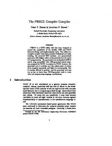
1. INTRODUCTION Field Programmable Gate Array (FPGAs) is an integrated circuit that contains a matrix of configurable logic blocks (CLBs) connected via programmable interconnects. FPGAs can be reprogrammed to desired application or functionality requirements after manufacturing. The FPGA configuration is usualy specified using a hardware description language (HDL) or a schematic design. The most common HDLs are VHDL and Verilog. The HDLs differs from conventional programming languages in a way that it is not a sequential but a parallel language, designed to describe computer hardware objects, logic, and algorithm. Logic blocks can be configured to perform complex combinational functions, or simple logic gates like AND, OR and XOR.There are two classes of HDLs. The first class includes standalone HDLs that have their own syntax, compilers and analyzers like Verilog or VHDL. The second class includes HDLs that are in fact compilers based on existing programming languages such as C, C++, C#, F, Java, Python, Ruby, Occam or Matlab. Hardware Description Languages (HDLs) have been existing for about 50 years now. The evolution of HDLs is presented in Figure 1[1].
Figure 1. The evolution of HDL tools. *
[email protected];
FPGA application can be created at a different levels of abstraction. The commonly used levels of abstraction are gate level, register-transfer level (RTL), and algorithmic level. Recent trends show that the creating application with highest level of abstraction is becoming more and more popular [1]. It is because of continuous FPGAs technology improvement and the need to automate the designing process.These tools enable the programmer to describe the behaviour of the system on a high-level of abstraction. Such tools are called Algorythmic Synthesis (AS), High-level synthesis (HLS), electronic system level (ESL) synthesis or behavioral synthesis.
2.
ALGORYTHMIC SYNTHESIS COMPILER
There are many actively developed algorythmic synthesis tools supporting advanced parallelism methods and features like Altera SDK for OpenCL, Vivado HLS, Mitrion-C, ImpulseC, Handel-C, DIME-C, eXCite, CatapultC, Cynthesizer 5, Synphpny C Compiler, CyberWorkBench, C-to-Silicon Compiler, BlueSpec Compiler, Panda Framework, SPARK and GAUT [1,12-21]. There was no tool meeting all the requirements for Hot Plasma Physics Experiment diagnostics systems e.g. KX1[22]. Such systems are built with many FPGAs. The process of creating a program for each FPGA separately is difficult and time-consuming. Writing parallel programs is more difficult than creating sequential ones. The programmer should care about synchronization, concurrency, data consistency and parallelization. Therefore, there was made a decision to build new one, that will fulfill all requirements. Python has been chosen as an algorithm description language fulfilling the above requirements and offering following features: •
large and comprehensive standard library including AST module. The AST module helps Python applications to process trees of the Python abstract syntax grammar,
•
numerical module (numpy) that support for large, multi-dimensional arrays and matrices, along with a large library of high-level mathematical functions to operate on these arrays,
•
free and open source software.
The created compiler have built-in methods [1-12] to facilitate fast implementation of parallel programs into FPGAs: •
Algorithm description is the process of capturing specifications as program-like description and making these available for next synthesis subtasks. Algorithm can be modelled using Graphical Modelling (GM), Low- level Programming Language (LLPL) or High-Level Programming Language (HLPL). Python has been choosen as HLPL. Example of matrix multipling algorithm descritipion is presented in Figure 2.
•
File parsing is the next step in the HLS process. The source code with algorithm description is translated to data structure called Abstract Syntax Tree (AST). AST is a tree representation of the abstract syntactic structure of the source code. Python have such functionality built-in and this feature is used in created compiler.
•
Scheduling is the most important task in the HLS process. It schedules operations, memory and interface access from Abstract Syntax Tree into clock cycles. There are two types of scheduling algorithms, based on the optimization goal (area or performance) and the specified constraints. Scheduling must ensure that the design uses faster functional units for operations on the critical path and slower units for operations outside the critical path. The goal of performance based scheduling is maximizing the utilization of hardware resources using parallelism extracting techniques. Parallelism Extraction (PE) can be created from the sequential code (SCPE) or loops. Loop Unrolling (LU) is the most parallelism exploiting method. Subsequent iterations of loop can be executed in parallel way, at the same time. If there are too many loop iterations to fit into single FPGA then partial LU can be applied. Partial unrolling may also be used to trade the area, power and performance of the resulting design. Loop merging (LM) exhibits loops-level parallelism. This technique applies to sequential loops and creates a single loop with the same functionality as the original loops. This transformation is used to reduce latency and
the area consumption in a design by allowing parallel execution, where possible, of loops that would normally execute in series. Automatic Pipelining (AP) is an optimization for achieving high clock speed hardware in a sequential portion of a code. The registers are added to the design in appropriate positions to minimize the combinatorial logic between registers and maximize the clock speed of the chip. Loop Pipelining (LP) provides a way to increase the throughput of a loop (or decreasing its overall latency) by initiating the next iteration of the loop before the current iteration has completed. Overlapping the execution of subsequent iterations of a loop exploits parallelism across the loop iterations. The number of cycles between iterations of the loop is called the initiation interval. In many cases loop pipelining may improve the resource utilization thus increasing the performance/area metric of the design. Hierarchical Synthesis (HS) is another way of exposing parallelism. While loop unrolling exploits instruction level parallelism and loop merging exploits loop level parallelism, hierarchy exploits function level (task-level) parallelism. HS can greatly simplify the design and integration tasks. •
Binding task assigns the operations and memory accesses with each clock cycle to available hardware units. A resource such as a functional, storage or interconnection unit can be shared by different operations, data accesses or data transfers if they are mutually exclusive. Two operations assigned to two different control steps are mutually exclusive since they will never execute simultaneously. Therefore a unit can be mapped to the same hardware unit. Sometimes, units must be bound into more than one FPGA, then Multi-FPGA Partitioning method should be applied (MFP),
•
Numerical Computing (NC) allowing matrix operations (algorithm described with an array) and automatic impelemntation.
3. ARCHITECTURE A developed tool is composed of three parts: •
Algorythmic synthesis Python Compiler ,
•
Python microcommands emulator,
•
VHDL framework.
Python Compiler get algorithm description as source input and translate it to output VHDL microinstructions. Input and output files are presented in Figures 2 and 3.
Figure 2. The example of algorithm description in Python Code.
Figure 2 contains matrix multipling algorithm implemented in Python. The first lines of the code import modules from library. In the next lines there is a definition of the method "dot" which will be translated to VHDL microcommands. This method has two input arguments "a1", "a2" and one output argument "r". These arguments are defined in the parameters section as "NBarray" type which means it is a natural binary array object. In the body of the "dot" there are three loops, multiplication and add operation on objects "a1" and "a2". The result of this operation will be moved to object "r". The compilation process can be widely paremetrized e.g. number of processors, registers or ram, word size, loop handlers, partitioning algorithm. During code processing the compiler analyzes python syntax using built-in AST module. After that AST objects are translated to CFG ( Control Flow Graph) objects. Finally, CFG objects are scheduled and binded to VHDL microinstructions. Example parameters sections is presented in Figure 3.
Figure 3. The example of Python parameters section.
An example of VHDL module output is presented in Figure 4.
Figure 4. The example of output VHDL code.
The VHDL output code is built from two sections which are constructed of microinstructions. Microinstructions consist of a mnemonic and three parameters. The first section describes requirements for the architecture resources. The output architecture is composed of processors, shared memory (registers, multiport memories) and multiplexers.The second part
of the file describes programs scheduled for each processor. Each processor can execute instructions independently so the program for each processor can be built from different number of instructions and clock cycles. Table 1 presents descriptions of most important microcommands supported by compiler. Table 1. Example microinstructions. Microcommand
Section
Description
PROC_NUM
1
Number of designed processors
DATA_WITH
1
Word data bits width
BUF_NUM
1
Number of buffers
REG_NUM
1
Number of registers
MEM_NUM
1
Number of memories
MEM_SIZE
1
Number of ports and size of specified memory
IO_MEM_NUM
1
Number of memories with external input/output port
CON_IO_MEM
1
Information about connection to external port for specified memory
PROC_BEGIN, PROC_END
2
Begins/Ends new clock cycle for current processor
SET_TNB_CST
2
Sets natural binary value for specified buffer
MOV_BUF_REG, MOV_REG_BUF, MOV_BUF_BUF
2
Moves the value of specified buffer/register to register/buffer
MOV_RES_BUF
2
Moves result from specified processor to buffer
MOV_MDAT_BUF, MOV_BUF_MDAT
2
Moves buffer/memory data to memory data/buffer for specified memory and port
MOV_BUF_MADR
2
Sets the address for specified memory and port
MOV_BUF_ARG1, MOV_BUF_ARG2
2
Moves buffer to arg1/arg2 for specified processor
RUN_NOP, RUN_ADD, RUN_SUB, RUN_MLP
2
Execute no operation/add operation/subtract operation/multiply operation
CMP_TNB_EQ, CMP_TNB_GEQ, CMP_TNB_LEQ,
2
Check if value in specified buffer is equal/greater/less with natural binary value
JMP_ABS_BEG
2
Jump to specified microinstruction in current proccessor
WAIT_WHILE
Wait for specified step (program counter) in current processor
Python microcommands emulator interprets the VHDL output file and debugs the architecture step by step. The value of signals, registers, memories can be verified at each clock. Such an approach enables a designer to find errors at an
early stage of the project. This procedure can be done very fast and automaticly on high level of abstraction. This can reduce designing time significantly. The example emulation code is presented in Figure 5.
Figure 5. The example of output VHDL code.
The last two lines of the code execute: - emulateVHDL- at this level the VHDL code is emulated by Architecture Emulator, - print "Emulated value is the same?" - print the results of emulation. VHDL framework is a VHDL library containig pseudocode (sections with microinstructions) definitions. The VHDL output module is synthesised with VHDL library with proprietary software. After that designed algorithm is mapped to hardware. Results for matrix multipling algorithm are presented in next chapter.
4. RESULTS The compiler and emulator have been tested. The code has been implemented in Stratix 3 family (Altera EP3SL110F1152C2) using Altera Quartus II. The results of matrix multiplying with different parameters are presented in Table 2.
Table 2. Performance and resource utilization report. Matrix dimension
8x8
16x16
64x64
64x64
Method
8 Partial Parallel
8 Partial Parallel
8 Partial Parallel
16 Partial Parallel
Memories
8-port memories
8-port memories
8-port memories
16-port memories
ALUTs utilized
2132
2098
2145
4330
Registers utilized
1600
1646
1737
3375
3312
12528
196848
197168
16
16
16
32
434.97 MHz
413.91 MHz
365.63 MHz
362.71 MHz
Memory utilized
bits
18 bits DSP block utilized Max. Frequency
The table presents the results for 8x8, 16x16,64x64 matrix multiplying using different number of processor and multiport memories. The python compiler translates HLPL algorithm descriptons to AST objects and then to CFG objects. After that the scheduler maps operations (multiply, sum) and interfaces access (registers read/write) from CFG objects into clock cycles. In this case, scheduling algorithms is based on the performance optimization goal with the specified
constraints. It uses Partial Loop Unrolling ana Parallelizing method. This method unroll the loops and place each loop to separate processor. Such an approach is suitable for big size matrix operations. It's worth mentioning that the bottleneck of big matrix multiplication is the operation of the access to the memory. In such cases it is advisable to use the multiport memory. In presented examples 8-port and 16-port memory are used. Current FPGA technology support only 2-port memories. Memories with bigger number of ports are constructed with shifter registers for address and data. Such memories works with lower frequency but sufficient in many cases.
5. CONCLUSIONS AND FUTURE WORK The HLS tool has been created. The presented HLS tool offers high flexibility and wide parametrization. Parallelizing methods have been implemented. The matrix multiplying has been made (see Chapter 4). The HLPL code was created with Python, then it was compiled to VHDL code. After the compilation, the design was passed for synthesis and implementation to a target device Altera Stratix 3 EP3SL110F1152C2 using the platform Altera Quartus II. The performance and resource utilization report was presented in Table 2. Designed projects can perform with frequency bigger than 362.71 Mhz. The great advantage of the presented solution are multiport memories. VHDL framework has implemented multiport memories with shifter registers and frequency dividers. The subject of further investigations will be: •
peformance optimizations - creating scheduling algorithms that enable working on a higher frequency,
•
resource usage optimizations - creating scheduling algorithms that enable reducing utilization of DSP block and logic cells ,
•
development of MFP method - creating binding algorithms that enable partitioning code to multi FPGA systems.
REFERENCES [1] Cieszewski, R, Poźniak, K, Romaniuk, Ryszard "Python Based High-Level Synthesis Compiler" in [Photonics Applications in Astronomy, Communications, Industry, and High-Energy Physics Experiments 2014 ], vol. 9290, 2014, ISBN 9781628413694, 92903A-1-92903A-8, International Society for Optics and Photonics (2014) [2] Coussy, P. and Morawiec, A., [High-level synthesis: from algorithm to digital circuit ], Springer (2008). [3] Gajski, D. D., Dutt, N. D., and CH, A., [High-level synthesis], vol. 34, Kluwer Boston (1992). [4] Cong, J., Liu, B., Neuendorffer, S., Noguera, J., Vissers, K., and Zhang, Z., “High-level synthesis for fpgas: From prototyping to deployment,” Computer-Aided Design of Integrated Circuits and Systems, IEEE Transactions on 30(4), 473–491 (2011). [5] Babb, J., Rinard, M., Moritz, C. A., Lee, W., Frank, M., Barua, R., and Amarasinghe, S., “Parallelizing applications into silicon,” in [Field-Programmable Custom Computing Machines, 1999. FCCM’99. Proceedings. Seventh Annual IEEE Symposium on ], 70–80, IEEE (1999). [6] Liang, Y., Rupnow, K., Li, Y., Min, D., Do, M. N., and Chen, D., “High-level synthesis: Productivity, performance, and software constraints,” Journal of Electrical and Computer Engineering 2012, 1 (2012). [7] Philippe, C., Ghizlane, L.-L., and Dominique, H., “Multiple word-length high-level synthesis,” EURASIP Journal on Embedded Systems 2008 (2008). [8] Gokhale, M. and Gomersall, D., “High level compilation for fine grained fpgas,” in [FPGAs for Custom Computing Machines, 1997. Proceedings., The 5th Annual IEEE Symposium on ], 165–173, IEEE (1997). [9] Asanovic, K., Bodik, R., Demmel, J., Keaveny, T., Keutzer, K., Kubiatowicz, J., Morgan, N., Patterson, D., Sen, K., Wawrzynek, J., et al., “A view of the parallel computing landscape,” Communications of the ACM 52(10), 56–67 (2009). [10] Gajski, D. D. and Ramachandran, L., “Introduction to high-level synthesis,” Design & Test of Computers, IEEE 11(4), 44–54 (1994). [11] Meredith, M., “A look inside behavioral synthesis,” EEtimes.com , 04–08 (2004). [12] Bowyer, B., “The ’why’ and ’what’ of algorithmic synthesis,” EEtimes.com (2005).
[13] Berdychowski, P. P. and Zabolotny, W. M., “C to vhdl compiler,” in [Photonics Applications in Astronomy, Communications, Industry, and High-Energy Physics Experiments 2010], 77451F–77451F, International Society for Optics and Photonics (2010). [14] Zabolotny, W. M., “Dual port memory based heapsort implementation for fpga,” in [Photonics Applications in Astronomy, Communications, Industry, and High-Energy Physics Experiments 2011 ], 80080E– 80080E,International Society for Optics and Photonics (2011). [15] Zabolotny, W. M., “Dual port memory based parallel programmable architecture for dsp in fpga,” in [Photonics Applications in Astronomy, Communications, Industry, and High-Energy Physics Experiments 2010 ], 77451E–77451E, International Society for Optics and Photonics (2010). [16] Zabolotny, W. M., “Clock-efficient and maintainable implementation of complex state machines in vhdl,” in [Photonics Applications in Astronomy, Communications, Industry, and High-Energy Physics Experiments 2006 ], 63470G–63470G, International Society for Optics and Photonics (2006). [17] Zabolotny, W. M., Czarski, T., Chernyshova, M., Czyrkowski, H., Dabrowski, R., Dominik, W., Jakubowska, K., Karpinski, L., Kasprowicz, G., Kierzkowski, K., et al., “Optimization of fpga processing of gem detector signal,” in [Photonics Applications in Astronomy, Communications, Industry, and High-Energy Physics Experiments 2011], 80080F–80080F, International Society for Optics and Photonics (2011). [18] Zabolotny, W. M., Pozniak, K. T., Romaniuk, R. S., Czarski, T., Kudla, I. M., Kierzkowski, K., Jezynski, T., Burghardt, A., and Simrock, S., “Design and simulation of fpga implementation of a rf control system for the tesla test facility,” in [Photonics Applications in Astronomy, Communications, Industry, and High-Energy Physics Experiments], 223–230, International Society for Optics and Photonics (2003). [19] Kolasinski, P. and Zabolotny, W., “Dsp algorithms in fpga: proposition of a new architecture,” in [Photonics Applications in Astronomy, Communications, Industry, and High-Energy Physics Experiments 2007], 69370N– 69370N, International Society for Optics and Photonics (2007). [20] Bujnowski, K., Pucyk, P., Pozniak, K., and Romaniuk, R., “Decomposition of matlab script for fpga implementation of real time simulation algorithms for llrf system in european xfel,” in [Photonics Applications in Astronomy, Communications, Industry, and High-Energy Physics Experiments 2007 ], 69370P–69370P, International Society for Optics and Photonics (2007). [21] Bujnowski, K., Siemionczyk, A., Pucyk, P., Szewinski, J., Pozniak, K., and Romaniuk, R., “Matlab script to c code converter for embedded processors of flash llrf control system,” in [Photonics Applications in Astronomy, Communications, Industry, and High-Energy Physics Experiments 2007 ], 69370O–69370O, International Society for Optics and Photonics (2007).