Feb 23, 2014 ... Can I use code written in C (or any other language) with/in amforth? ..... The
Atmel tools AVR ISP MK2 and Dragon are not that expensive and ...
AmForth Documentation Release 6.6
Matthias Trute
August 09, 2017
CONTENTS
1
User’s Manual 1.1 User’s Manual For Linux . . . . . . . . . . . . . . . . . . . . . . . . . . . . . . . . . . . . . . . 1.2 User’s Manual for Windows . . . . . . . . . . . . . . . . . . . . . . . . . . . . . . . . . . . . . 1.3 Instructions for Building amforth-6-6 using Atmel Studio 6.1 Components . . . . . . . . . . . .
1 1 4 10
2
FAQ 2.1 2.2 2.3 2.4 2.5 2.6 2.7 2.8 2.9 2.10 2.11 2.12 2.13 2.14 2.15 2.16 2.17 2.18 2.19 2.20 2.21
. . . . . . . . . . . . . . . . . . . . .
. . . . . . . . . . . . . . . . . . . . .
. . . . . . . . . . . . . . . . . . . . .
. . . . . . . . . . . . . . . . . . . . .
. . . . . . . . . . . . . . . . . . . . .
. . . . . . . . . . . . . . . . . . . . .
. . . . . . . . . . . . . . . . . . . . .
. . . . . . . . . . . . . . . . . . . . .
. . . . . . . . . . . . . . . . . . . . .
. . . . . . . . . . . . . . . . . . . . .
. . . . . . . . . . . . . . . . . . . . .
. . . . . . . . . . . . . . . . . . . . .
. . . . . . . . . . . . . . . . . . . . .
. . . . . . . . . . . . . . . . . . . . .
. . . . . . . . . . . . . . . . . . . . .
13 13 13 13 14 14 14 15 15 15 15 15 15 15 15 16 16 16 16 16 16 17
. . . . . . .
. . . . . . .
. . . . . . .
. . . . . . .
. . . . . . .
. . . . . . .
. . . . . . .
. . . . . . .
. . . . . . .
. . . . . . .
. . . . . . .
. . . . . . .
. . . . . . .
. . . . . . .
. . . . . . .
19 19 19 25 28 31 43 44
4
Commented Projects 4.1 Nodes on a RS485 Bus . . . . . . . . . . . . . . . . . . . . . . . . . . . . . . . . . . . . . . . . 4.2 Date/Time to unix time and back . . . . . . . . . . . . . . . . . . . . . . . . . . . . . . . . . .
47 47 63
5
Cookbook 71 5.1 Popular Boards . . . . . . . . . . . . . . . . . . . . . . . . . . . . . . . . . . . . . . . . . . . . 71 5.2 General Code Examples . . . . . . . . . . . . . . . . . . . . . . . . . . . . . . . . . . . . . . . 80 5.3 Programming and Debugging . . . . . . . . . . . . . . . . . . . . . . . . . . . . . . . . . . . . 101
3
Where do I find more information? . . . . . . . . . . . . . . . . . . How do I start with amforth? . . . . . . . . . . . . . . . . . . . . . . How do I use amforth interactively? . . . . . . . . . . . . . . . . . . What means ?? . . . . . . . . . . . . . . . . . . . . . . . . . . . . There are no hexfiles in the distribution archive! . . . . . . . . . . . I get no serial prompt! . . . . . . . . . . . . . . . . . . . . . . . . . What do all the words do? . . . . . . . . . . . . . . . . . . . . . . . I miss a word! . . . . . . . . . . . . . . . . . . . . . . . . . . . . . Can I embed amforth into other programs? . . . . . . . . . . . . . . Can I use code written in C (or any other language) with/in amforth? What means the GPL for my programs? . . . . . . . . . . . . . . . . Why should I send you my code? . . . . . . . . . . . . . . . . . . . Does amforth run on hardware xy? . . . . . . . . . . . . . . . . . . What about the fuses? . . . . . . . . . . . . . . . . . . . . . . . . . What about boot loaders? . . . . . . . . . . . . . . . . . . . . . . . What do I need for linux? . . . . . . . . . . . . . . . . . . . . . . . How do I use Atmel’s assembler with linux? . . . . . . . . . . . . . What resources are available in my own assembly words? . . . . . . What is the release policy? . . . . . . . . . . . . . . . . . . . . . . . How do I send forth code to the system? . . . . . . . . . . . . . . . . I found a bug . . . . . . . . . . . . . . . . . . . . . . . . . . . . . .
Technical Guide 3.1 First Steps . . . . . 3.2 Architecture . . . . 3.3 Compiler . . . . . . 3.4 Standard Wordlists . 3.5 Hardware . . . . . . 3.6 Source Organization 3.7 Tools . . . . . . . .
. . . . . . .
. . . . . . .
. . . . . . .
. . . . . . .
. . . . . . .
. . . . . . .
. . . . . . .
. . . . . . .
. . . . . . .
. . . . . . .
. . . . . . .
. . . . . . .
. . . . . . .
. . . . . . .
. . . . . . .
. . . . . . .
. . . . . . .
. . . . . . .
. . . . . . .
. . . . . . .
. . . . . . .
. . . . . . .
. . . . . . .
. . . . . . .
. . . . . . .
. . . . . . .
i
5.4 5.5 5.6
Hardware Modules (Generic) . . . . . . . . . . . . . . . . . . . . . . . . . . . . . . . . . . . . 128 Hardware Modules (AVR) . . . . . . . . . . . . . . . . . . . . . . . . . . . . . . . . . . . . . . 129 Hardware Modules (MSP430) . . . . . . . . . . . . . . . . . . . . . . . . . . . . . . . . . . . . 153
6
Recognizers 155 6.1 Version 4 . . . . . . . . . . . . . . . . . . . . . . . . . . . . . . . . . . . . . . . . . . . . . . . 155 6.2 Outdated . . . . . . . . . . . . . . . . . . . . . . . . . . . . . . . . . . . . . . . . . . . . . . . 156 6.3 Namespace RFD . . . . . . . . . . . . . . . . . . . . . . . . . . . . . . . . . . . . . . . . . . . 156
7
Reference Card 7.1 General . . . . . . . . . 7.2 Arithmetics (AVR8) . . 7.3 Compare (AVR8) . . . . 7.4 Compiler (AVR8) . . . 7.5 Dictionary (AVR8) . . . 7.6 Environment (AVR8) . . 7.7 Extended VM (AVR8) . 7.8 Interrupt (AVR8) . . . . 7.9 Logic (AVR8) . . . . . 7.10 MCU (AVR8) . . . . . 7.11 Memory (AVR8) . . . . 7.12 Multitasking (AVR8) . . 7.13 Numeric IO (AVR8) . . 7.14 Search Order (AVR8) . 7.15 Stack (AVR8) . . . . . . 7.16 String (AVR8) . . . . . 7.17 System (AVR8) . . . . . 7.18 System Value (AVR8) . 7.19 System Variable (AVR8) 7.20 Time (AVR8) . . . . . . 7.21 Tools (AVR8) . . . . . .
. . . . . . . . . . . . . . . . . . . . .
. . . . . . . . . . . . . . . . . . . . .
. . . . . . . . . . . . . . . . . . . . .
. . . . . . . . . . . . . . . . . . . . .
. . . . . . . . . . . . . . . . . . . . .
. . . . . . . . . . . . . . . . . . . . .
. . . . . . . . . . . . . . . . . . . . .
. . . . . . . . . . . . . . . . . . . . .
. . . . . . . . . . . . . . . . . . . . .
. . . . . . . . . . . . . . . . . . . . .
. . . . . . . . . . . . . . . . . . . . .
. . . . . . . . . . . . . . . . . . . . .
. . . . . . . . . . . . . . . . . . . . .
. . . . . . . . . . . . . . . . . . . . .
. . . . . . . . . . . . . . . . . . . . .
. . . . . . . . . . . . . . . . . . . . .
. . . . . . . . . . . . . . . . . . . . .
. . . . . . . . . . . . . . . . . . . . .
. . . . . . . . . . . . . . . . . . . . .
. . . . . . . . . . . . . . . . . . . . .
. . . . . . . . . . . . . . . . . . . . .
. . . . . . . . . . . . . . . . . . . . .
. . . . . . . . . . . . . . . . . . . . .
. . . . . . . . . . . . . . . . . . . . .
. . . . . . . . . . . . . . . . . . . . .
. . . . . . . . . . . . . . . . . . . . .
. . . . . . . . . . . . . . . . . . . . .
. . . . . . . . . . . . . . . . . . . . .
. . . . . . . . . . . . . . . . . . . . .
. . . . . . . . . . . . . . . . . . . . .
. . . . . . . . . . . . . . . . . . . . .
. . . . . . . . . . . . . . . . . . . . .
. . . . . . . . . . . . . . . . . . . . .
. . . . . . . . . . . . . . . . . . . . .
. . . . . . . . . . . . . . . . . . . . .
. . . . . . . . . . . . . . . . . . . . .
. . . . . . . . . . . . . . . . . . . . .
. . . . . . . . . . . . . . . . . . . . .
. . . . . . . . . . . . . . . . . . . . .
157 157 157 158 158 159 159 159 160 160 160 160 161 161 161 161 162 162 162 163 163 163
History 8.1 9.7.2015: release 5.9 . . 8.2 25.3.2015: release 5.8 . 8.3 1.2.2015: release 5.7 . . 8.4 22.12.2014: release 5.6 . 8.5 6.10.2014: release 5.5 . 8.6 16.8.2014: release 5.4 . 8.7 7.5.2013: release 5.3 . . 8.8 23.12.2013: release 5.2 . 8.9 5.4.2013: release 5.1 . . 8.10 27.12.2012: release 5.0 . 8.11 27.7.2012: release 4.9 . 8.12 26.3.2012: release 4.8 . 8.13 4.2.2012: release 4.7 . . 8.14 6.10.2011: release 4.6 . 8.15 29.6.2011: release 4.5 . 8.16 24.5.2011: release 4.4 . 8.17 1.5.2011: release 4.3 . . 8.18 19.9.2010: release 4.2 . 8.19 2.9.2010: release 4.1 . . 8.20 1.7.2010: release 4.0 . . 8.21 25.5.2010: release 3.9 . 8.22 25.4.2010: release 3.8 . 8.23 24.1.2010: release 3.7 . 8.24 1.10.2009: release 3.6 . 8.25 1.9.2009: release 3.5 . . 8.26 11.4.2009: release 3.4 .
. . . . . . . . . . . . . . . . . . . . . . . . . .
. . . . . . . . . . . . . . . . . . . . . . . . . .
. . . . . . . . . . . . . . . . . . . . . . . . . .
. . . . . . . . . . . . . . . . . . . . . . . . . .
. . . . . . . . . . . . . . . . . . . . . . . . . .
. . . . . . . . . . . . . . . . . . . . . . . . . .
. . . . . . . . . . . . . . . . . . . . . . . . . .
. . . . . . . . . . . . . . . . . . . . . . . . . .
. . . . . . . . . . . . . . . . . . . . . . . . . .
. . . . . . . . . . . . . . . . . . . . . . . . . .
. . . . . . . . . . . . . . . . . . . . . . . . . .
. . . . . . . . . . . . . . . . . . . . . . . . . .
. . . . . . . . . . . . . . . . . . . . . . . . . .
. . . . . . . . . . . . . . . . . . . . . . . . . .
. . . . . . . . . . . . . . . . . . . . . . . . . .
. . . . . . . . . . . . . . . . . . . . . . . . . .
. . . . . . . . . . . . . . . . . . . . . . . . . .
. . . . . . . . . . . . . . . . . . . . . . . . . .
. . . . . . . . . . . . . . . . . . . . . . . . . .
. . . . . . . . . . . . . . . . . . . . . . . . . .
. . . . . . . . . . . . . . . . . . . . . . . . . .
. . . . . . . . . . . . . . . . . . . . . . . . . .
. . . . . . . . . . . . . . . . . . . . . . . . . .
. . . . . . . . . . . . . . . . . . . . . . . . . .
. . . . . . . . . . . . . . . . . . . . . . . . . .
. . . . . . . . . . . . . . . . . . . . . . . . . .
. . . . . . . . . . . . . . . . . . . . . . . . . .
. . . . . . . . . . . . . . . . . . . . . . . . . .
. . . . . . . . . . . . . . . . . . . . . . . . . .
. . . . . . . . . . . . . . . . . . . . . . . . . .
. . . . . . . . . . . . . . . . . . . . . . . . . .
. . . . . . . . . . . . . . . . . . . . . . . . . .
. . . . . . . . . . . . . . . . . . . . . . . . . .
. . . . . . . . . . . . . . . . . . . . . . . . . .
. . . . . . . . . . . . . . . . . . . . . . . . . .
. . . . . . . . . . . . . . . . . . . . . . . . . .
. . . . . . . . . . . . . . . . . . . . . . . . . .
. . . . . . . . . . . . . . . . . . . . . . . . . .
. . . . . . . . . . . . . . . . . . . . . . . . . .
165 165 165 165 165 166 166 166 166 167 167 168 168 169 169 169 169 170 170 170 171 171 171 172 172 172 172
8
ii
8.27 8.28 8.29 8.30 8.31 8.32 8.33 8.34 8.35 8.36 8.37 8.38 8.39 8.40 8.41 8.42 8.43 8.44 8.45 8.46 8.47 8.48 8.49 8.50 8.51 8.52 8.53 8.54 8.55 8.56 8.57 8.58 8.59
22.2.2009: release 3.3 . 10.1.2009: release 3.2 . 10.11.2008: release 3.1 . 17.10.2008: release 3.0 . 1.8.2008: release 2.9 . . 27.6.2008: release 2.8 . 5.4.2007: release 2.7 . . 27.1.2008: release 2.6 . 6.12.2007: release 2.5 . 11.10.2007: release 2.4 . 29.7.2007: release 2.3 . 17.6.2007: release 2.2 . 22.5.2007 release 2.1 . . 2.5.2007 release 2.0 . . 25.4.2007 release 1.9 . . 10.4.2007 release 1.8 . . 3.4.2007 release 1.7 . . 25.3.2007 release 1.6 . . 14.3.2007 release 1.5 . . 5.3.2007 release 1.4 . . 24.2.2007 release 1.3 . . 3.2.2007 release 1.2 . . 20.1.2007 release 1.1 . . 4.1.2007 release 1.0 . . 17.12.2006 release 0.9 . 7.12.2006 release 0.8 . . 24.11.2006 release 0.7 . 20.11.2006 release 0.6 . 13.11.2006 release 0.5 . 5.11.2006 release 0.4 . . 31.10.2006 release 0.3 . 27.10.2006 release 0.2 . 16.10.2006 release 0.1 .
. . . . . . . . . . . . . . . . . . . . . . . . . . . . . . . . .
. . . . . . . . . . . . . . . . . . . . . . . . . . . . . . . . .
. . . . . . . . . . . . . . . . . . . . . . . . . . . . . . . . .
. . . . . . . . . . . . . . . . . . . . . . . . . . . . . . . . .
. . . . . . . . . . . . . . . . . . . . . . . . . . . . . . . . .
. . . . . . . . . . . . . . . . . . . . . . . . . . . . . . . . .
. . . . . . . . . . . . . . . . . . . . . . . . . . . . . . . . .
. . . . . . . . . . . . . . . . . . . . . . . . . . . . . . . . .
. . . . . . . . . . . . . . . . . . . . . . . . . . . . . . . . .
. . . . . . . . . . . . . . . . . . . . . . . . . . . . . . . . .
. . . . . . . . . . . . . . . . . . . . . . . . . . . . . . . . .
. . . . . . . . . . . . . . . . . . . . . . . . . . . . . . . . .
. . . . . . . . . . . . . . . . . . . . . . . . . . . . . . . . .
. . . . . . . . . . . . . . . . . . . . . . . . . . . . . . . . .
. . . . . . . . . . . . . . . . . . . . . . . . . . . . . . . . .
. . . . . . . . . . . . . . . . . . . . . . . . . . . . . . . . .
. . . . . . . . . . . . . . . . . . . . . . . . . . . . . . . . .
. . . . . . . . . . . . . . . . . . . . . . . . . . . . . . . . .
. . . . . . . . . . . . . . . . . . . . . . . . . . . . . . . . .
. . . . . . . . . . . . . . . . . . . . . . . . . . . . . . . . .
. . . . . . . . . . . . . . . . . . . . . . . . . . . . . . . . .
. . . . . . . . . . . . . . . . . . . . . . . . . . . . . . . . .
. . . . . . . . . . . . . . . . . . . . . . . . . . . . . . . . .
. . . . . . . . . . . . . . . . . . . . . . . . . . . . . . . . .
. . . . . . . . . . . . . . . . . . . . . . . . . . . . . . . . .
. . . . . . . . . . . . . . . . . . . . . . . . . . . . . . . . .
. . . . . . . . . . . . . . . . . . . . . . . . . . . . . . . . .
. . . . . . . . . . . . . . . . . . . . . . . . . . . . . . . . .
. . . . . . . . . . . . . . . . . . . . . . . . . . . . . . . . .
. . . . . . . . . . . . . . . . . . . . . . . . . . . . . . . . .
. . . . . . . . . . . . . . . . . . . . . . . . . . . . . . . . .
. . . . . . . . . . . . . . . . . . . . . . . . . . . . . . . . .
. . . . . . . . . . . . . . . . . . . . . . . . . . . . . . . . .
. . . . . . . . . . . . . . . . . . . . . . . . . . . . . . . . .
. . . . . . . . . . . . . . . . . . . . . . . . . . . . . . . . .
. . . . . . . . . . . . . . . . . . . . . . . . . . . . . . . . .
. . . . . . . . . . . . . . . . . . . . . . . . . . . . . . . . .
. . . . . . . . . . . . . . . . . . . . . . . . . . . . . . . . .
. . . . . . . . . . . . . . . . . . . . . . . . . . . . . . . . .
173 173 173 173 174 174 174 174 175 175 175 176 176 176 176 176 177 177 177 177 178 178 178 179 179 179 179 179 180 180 180 180 180
iii
iv
CHAPTER
ONE
USER’S MANUAL
User’s Manual For Linux Initial Setup This guide makes a few assumtions. Your linux should be a fairly recent linux distribution. For this document an Ubuntu 12.04 LTS is used, others should work in a similiar way. Most of the following is for AVR8. The MSP430 is only for the TI Launchpad and needs no further configuration (yet). First you’ll have to install some packages with the package manager: • wine (any version, only for AVR8 • naken_asm (any version, only for MSP430) • ant or make (any version) • avrdude (only for AVR8) • mspdebug (any version, only for MSP430) They may need quite a lot more packages especially wine, install all of them. Next download the amforth package and un-tar (or unzip) it into a new, empty folder: > pwd .../amforth > ls > tar xvfz amforth-x.y.tgz .. lots of files > ls appl common avr8 msp430 doc tools >
examples
lib
LICENSE.txt
readme.txt
Now you need to download the Atmel-Assembler package from the same source as you downloaded the amforth sources. Extract in the in the amforth base directory. This will create a subdirectory avr8/Atmel that contains the assembler (as an exe file) and the necessary include files. > ls avr8/Atmel avrasm2.exe Appnotes2/ >
Testing To test if the installation is complete, change into the directory appl/template. There run either make or ant with the target name template.hex to test the assembler setup.
1
AmForth Documentation, Release 6.6
> make template.hex wine ../../avr8/Atmel/avrasm2.exe -I ../../avr8(Atmel/Appnotes2 -I ../../avr8/devices/atmega1284p -I ../../avr8 -I ../../common -I ../../core/devices/atmega1284p -fI -v0 -e template.eep.hex -l template.lst template.asm >
Ant works similiar, note the warning at startup, it can safely ignored: > ant template.hex Unable to locate tools.jar. Expected to find it in /usr/lib/jvm/java-6-openjdk-amd64/lib/tools.jar Buildfile: ....amforth/appl/template/build.xml template.hex: [echo] Producing Hexfiles for atmega128 BUILD SUCCESSFUL Total time: 4 seconds >
After this step, there should be a number of new files in the directory: > ls build.xml template.hex makefile
dict_appl.inc template.asm template.map dict_appl_core.inc template.eep.hex template.lst words
If something went wrong, read the error messages, fix them and repeat this step until all is well.
Create Your Project If everything works fine, it is now possible to start your own project. This as simple as making a copy of the template directory and editing a few files there. > pwd ... amforth/appl > cp -r template my > cd my >
Now edit the files template.asm and makefile (or build.xml if you use ant). The file template.asm has a lot of settings, to get a quick start only the lines .equ BAUD = 9600 .include "drivers/usart_0.asm"
may need to be changed. The baud number should be obvious. The line usart_x.asm defines the usart port of the controller on which the command prompt will be available. There are only real usart ports available, no USB devices (this may change in future releases..) In the makefile find the lines # set the fuses according to your MCU LFUSE=0xnn HFUSE=0xnn # some MCU have this one, see write-fuses target below EFUSE=0xnn
resp. the build.xml for ant: Writing fuses
and change the fuses to meet you hardware settings. Be careful with these numbers, they can potentially corrupt your controller cpu beyond repair. The next essential setting is the controller itself # the MCU should be identical to the device MCU=atmega1284p
in the build.xml find and change all occurances that look like mcu="atmega1284p"
with the proper name. The mcu names are taken verbatim as file names in the avr8/Atmel/Appnotes2 directory and as directory names in the avr8/devices directory. Case is significant (should be almost always lower case). With these changes, rebuild the hex files as described above.
Program The Controller Hardware and System Setup The last and final step is to transfer the hex files to the controller. The build tools use the program avrdude. To get the hex files to the controller a special hardware called programmer is needed. There are many different ones available, ranging from simple parallelport tools like the STK200 to expensive tools like the Atmel JTAG ICE MK2. Dont start trying to use exotic tools like ponyser or other self-made el-cheapo tools unless you know what you’re doing. The Atmel tools AVR ISP MK2 and Dragon are not that expensive and work with the USB port of your computer. Linux needs a file named /etc/udev/rules.d/99-atmel.rules to make them accessible for users: # Atmel AVR ISP mkII SUBSYSTEM=="usb", ATTRS{idVendor}=="03eb", ATTRS{idProduct}=="2104", GROUP="users", MODE="0660" # usbprog bootloader ATTRS{idVendor}=="1781", ATTRS{idProduct}=="0c62", GROUP="users", MODE="0660" # USBasp programmer ATTRS{idVendor}=="16c0", ATTRS{idProduct}=="05dc", GROUP="users", MODE="0660" # USBtiny programmer ATTRS{idVendor}=="1781", ATTRS{idProduct}=="0c9f", GROUP="users", MODE="0660"
Note, that the correct GROUP name should include one of the groups your linux account is a member of: > id uid=1000(user) gid=1000(user) groups=1000(user),4(adm),24(cdrom), 27(sudo),30(dip),46(plugdev),109(lpadmin),124(sambashare),125(libvirtd)
Here the GROUP name “users” would not work! But “user” or “plugdev” would do. If you do not have a setup like this, only root can access the programmer. If you want to use the parallelport programmer STK200, your account should be a member of the “lp” group (check with ls -l /dev/parport*). Any changes to the rules file are detected almost immediately, there should be no reason to restart any linux program.
1.1. User’s Manual For Linux
3
AmForth Documentation, Release 6.6
Project Setup If your hardware setup is finished, you need to edit the makefile or build.xml to reflect the settings. In the makefile find and edit the lines USB=-c avr911 -P /dev/ttyUSB3 PP=-c stk200 -P /dev/parport0 JTAG=-c jtag2 -P /dev/ttyUSB2 BURNER=$(USB)
The build.xml is different. This file uses a property file named programmer.properties to set the name and the port of the programmer hardware. The build.xml file uses a substring from the label to define the programmer. If you want to use e.g. the AVR Dragon as the programmer, just use the name “dragon” as programmer idenifier in your build.xml. The ant utility will expand this to “avr.programmer.port” for the -P parameter and “avr.programmer.” to the -c parameter to generate the right command line for avrdude from the property file. Serial programmers may be difficult while getting the right port name if using RS232-to-USB converters. The mapping may change over time (e.g. every reboot or USB bus reset). If everything goes ok, the final command make template should re-generate the hex files and transfer them to the controller. The default program output should be verbose enough to track any error messages.
User’s Manual for Windows by Karl Lunt for amforth v4.2 (updated for v6.1) Document contributed to the amforth project on SourceForge.net.
Introduction This manual describes the amforth programming language and provides details on how to customize the standard release for use on your target platform. This document focuses on developing amforth applications in the Windows environment, using Atmel’s freeware AVRStudio4. For information on developing amforth applications in the Linux/Unix environment, consult the Web. amforth is a variant of the ans94 Forth language, designed for the AVR ATmega family of microcontrollers (MCUs). amforth was developed and maintained by Matthias Trute; the amforth project is hosted and maintained on SourceForge.net (http://sourceforge.net/projects/amforth). You create your amforth application by creating a custom template file, (optionally) modifying some of the files included in the distribution set, assembling them with AVRStudio4, then moving the resulting object file into flash in the target hardware. Your amforth application resides in flash, using very little RAM or EEPROM. amforth is fully interactive. You can connect your target hardware to a serial port on your host PC, run a comm program such as Hyperterm, and develop additional Forth words and applications on the target. Each word you create interactively is also stored in flash and is available following reset or power-cycle of the target. You can select one of your amforth words to be the boot task, which will run automatically on the next reset or power-cycle. You can also write interrupt service routines (ISRs) in amforth for handling low-level, time-critical events. This manual assumes familiarity with Atmel’s AVRStudio4 development suite (Windows OS); some knowledge of AVR assembly language programming is helpful but not necessary for basic use of the amforth language. You can download the free AVRStudio4 suite from Atmel (http://www.atmel.com/dyn/products/tools_card.asp?tool_id=2725). You can use version 4.2 or higher; note that you need to fill out a fairly simple registration page to complete the download. This manual also assumes a working knowledge of the Forth programming language. If you are new to Forth, or if you need a quick refresher or a reference page, you can find a full Web version of Leo Brodie’s marvelous book, “Starting Forth,” online at http://home.iae.nl/users/mhx/sf.html.
4
Chapter 1. User’s Manual
AmForth Documentation, Release 6.6
About this document I created this document to support Matthias’ work on amforth. He has designed an excellent Forth that I enjoy using, but I thought newcomers to amforth could use a bit more detailed explanation on setting up an application. As my contribution to his amforth project, I’m providing this user’s manual. This document was written using OpenOffice version 3.2.0. You can download a copy of OpenOffice at the project’s website: www.openoffice.org I have contributed this document to Matthias for inclusion in his project, with the hope that others will edit and expand this text, to make amforth even better. If you modify this document, please include this section (with suitable additions) and include my name in the list of contributors. Karl Lunt, Bothell, WA USA
A quick look inside amforth amforth v4.2 is available as a single downloadable file (amforth-4.2.zip). Download this file into your working folder (I’ll use c:\projects\amforth-4.2 throughout this document) and unzip them, preserving the subdirectory structure. You should end up with the following subdirectory layout: c:\projects\amforth-x.y\ \appl \common \avr8 \msp430 \doc \examples \lib \tools
ascii-xfr -s -c 10 -l
100
devices/atmega32.frt > /dev/ttyS0
can be used. amforth does not currently support any kind of flow control. Any transfer has to be slow enough to not overrun the buffers. A more sophisticated approach is described in Shells And Upload
I found a bug Too bad. Please send all information to the Mailling List
2.21. I found a bug
17
AmForth Documentation, Release 6.6
18
Chapter 2. FAQ
CHAPTER
THREE
TECHNICAL GUIDE
First Steps The first steps require an ATmega micro controller or a TI Launchpad 430 with a MSP430G2553 controller. The AVR needs a separate RS232 connection to an PC, the MSP430 works with the USB connection for both the command terminal and the reprogramming.
User Interface amforth has a simple user interface. It is available as a serial port. > cold amforth 5.0 ATmega16 8000 kHz > words nr> n>r (i!) !i @i @e !e nip not s>d up! up@ ... >
Next Steps The next steps are performing some actions like LED on / off and defining new commands to extent the interpreter. The Cookbook has a lot of recipes for both.
Architecture Overview amforth is a 16 bit Forth implementing the indirect threading model. The flash memory contains the whole dictionary. The RAM contains buffers, variables and the stacks. Depending on the platform, either the EEPROM or a special section of the flash is used for vital data such as pointers or configuration settings. The compiler is a classic compiler without any optimization support. Amforth uses all of the CPU registers internally: The data stack pointer, the instruction pointer, the user pointer, and the Top-Of-Stack cell. The hardware stack is used as the return stack. Some registers are used for temporary data in primitives.
Text Interpreter The interpreter is a line based command interpreter. It based upon :REFILL to acquire the next line of characters, located at a position SOURCE points to. While processing the line, the pointer >IN is adjusted accordingly. Both words REFILL and SOURCE are USER based deferred words which allows to use any input source on a thread specific level. The interpreter itself does not use any static buffers or variables (>IN is a USER variable as well).
19
AmForth Documentation, Release 6.6
A given string is handled by INTERPRET which splits it into whitespace delimited words. Every word is processed using a list of recognizers. Processing ends either when the string end is reached or an exception occurs. SOURCE and REFILL SOURCE provides an addr/len string pair that does not change during processing. The task of REFILL is to fill the string buffer, SOURCE points to when finished. There is one default input source: The terminal input buffer. This buffer gets filled with REFILL-TIB that reads from the serial input buffers (KEY). SOURCE points to the Terminal Input Buffer itself. Another input source are plain strings, used by EVALUATE. Recognizer Recognizer are a part of the text (command) interpreter. They are responsible for analyzing a single word. The result consists of two elements: The actual data (if any) and an object like identifier connected with certain
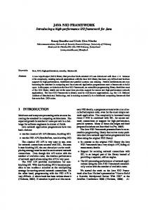
Interpret
Get Next Word No More Words Got one End
Recognize
Check State Compile Interpret Compile
Execute
The Forth text interpreter methods. reads from the input source and splits it into whitespace delimited words. Each word is fed into a list of actions which parse it. If the parsing is successful (e.g. it is a number or a word from the dictionary) the recognizer leaves the data and an method table to deal with it. Depending on the interpreter state one of the methods is executed to finally process the data. The first method is called in interpreter state. It is usually a noop, since the recognizer has done all the work already. 20
Chapter 3. Technical Guide
AmForth Documentation, Release 6.6
The 2nd method is responsible to perform the compile time semantics. That usually means to write it into the dictioanary or to execute immediate words. The third method is used by :command‘postpone‘ to compile the compilation semantics. It honors the immediate flags as well. Recognize is an iteration over a recognizer stack until the first parsing methods returns something different than DT:NULL. If the recognizer stack is exhausted without a match, the DT:NULL return value is generated. The string location that is passed to the parse actions is preserved and is restored for every iteration cycle.
Get Recognizer Stack
Rec-Stack Exhausted? Yes
Consume Rec-TOS DT:NULL
DT:NULL
Call Parse Action Success End
A recognizer consists of a few words that work together. To ease maintenance, a naming convention is used: The recognizer itself is named with the prefix rec:. The method table name gets the prefix r: followed by the same name as the recognizer. POSTPONE serialises the parsed data as literals and adds the compile action from the method table. This an almost generic operation, it depends only on the number of cells from the parsing actions. Recognizer List
The interpreter uses a list of recognizers. set-recognizers.
They are managed with the words get-recognizers and
The entries in the list are called in order until the first one returns a different result but DT:NULL. If the list is exhausted and no one succeeds, the DT:NULL is delivered nevertheless and leads to the error reactions. The standard recognizer list is defined as follows : default-recs ['] rec:intnum ['] rec:word 2 forth-recognizer set-recognizers ;
3.2. Architecture
21
AmForth Documentation, Release 6.6
The standard word marker resets the recognizer list as well. INTERPRET
The interpreter is responsible to split the source into words and to call the recognizers. It also maintains the state. : interpret begin parse-name ?dup if drop exit then forth-recognizer recognize ( addr len -- i*x r:table ) state @ if i-cell+ then \ get compile time action @i execute ?stack again ;
recognize always returns a valid method table. If no recognizer succeeds, the DT:NULL is returned with the addr/len of the unknown-to-handle word. API
Every recognizer has a method table for the interpreter to handle the data and a word to check (and convert) whether a string matches the criteria for a certain data type. \ order is important! :noname ... ; \ interpret action :noname ... ; \ compile action :noname ... ; \ postpone action dt-token: dt:foo : rec:foo ( addr len -- i*x dt:foo | DT:NULL ) ... ;
The word rec:foo is the actual parsing action of the recognizer. It analyzes the string it gets. There are two results possible: Either the word is recognized and the address of the data token is returned or the NULL data token is used which is actually a predefined method table named DT:NULL. The calling parameters to rec:foo are the address and the length of a word in RAM. The recognizer must not change it. The result (i*x) is the parsed and converted data and the method table to deal with it. There is a standard method table that does not require additional data (i*x is empty) and which is used to communicate the “not-recognized” information: r:fail. Its method table entries throw the exception -13 if called. Other pre-defined method tables are dt:num to deal with single cell numeric data, dt:dnum to work with double cell numerics and dt:xt to execute, compile and postpone execution tokens XT from the dictionary. The words in the method tables get the output of the recognizer as input on the data stack. They are excpected to consume them during their work. Default (NULL)
This is a special system level recognizer. It is never called actually but its data token (DT:NULL) is used as both a error flag and for the final error actions. Its methods get the addr/len of a single word. They consume it by printing the string and throwing an exception when called. The effect is to get back to the command prompt if catched inside the quit loop. :noname type -13 throw ; dup dup dt-token: dt:null \ this definition is never called actually : rec:fail ( addr len -- r:fail) 2drop dt:null ;
22
Chapter 3. Technical Guide
AmForth Documentation, Release 6.6
NUMBER
The number recognizer identifies numeric data in both single and double precision. Depending on the actual data width, two different data tokens are returned. The postpone action follows the standard definitions by not allowing to postpone numbers. Instead the number is printed and an exception is thrown. ' noop ' literal :noname . -48 throw ; \ subject to dispute dt-token: dt:num ' noop ' 2literal :noname d. -48 throw ; \ subject to dispute dt-token: dt:dnum : rec:intnum ( addr len -- n r:num | d r:dnum | r:fail ) number if 1 = if dt:num else dt:dnum then else dt:null then ;
FIND
This recognizer tries to find the word in the dictionary. If sucessful, the execution token and the flags are returned. The data token contains words to execute and correctly deal with immediate words for compiling and postponing. ( XT flags -- ) :noname drop execute ; :noname 0> if compile, else execute then ; :noname 0> if postpone [compile] then , ; dt-token: dt:xt : rec:word ( addr len -- XT flags dt:xt | dt:null ) find-name ?dup if dt:xt else dt:null then ;
Multitasking amforth does not implement multitasking directly. It provides the basic functionality however. Within IO words the deferred word PAUSE is called whenever possible. This word is initialized to do nothing (NOOP).
Exceptions Amforth uses and supports exceptions as specified in the ANS wordset. It provides the CATCH and THROW commands. The outermost catch frame is located at the interpreter level in the word QUIT. If an exception with a negative value is catched, QUIT will print a message with this number and and re-start itself. Positive values silently restart QUIT. 3.2. Architecture
23
AmForth Documentation, Release 6.6
The next table lists the exceptions, amforth uses itself. Exception -1 -2 -4 -13 -16 -50
Meaning silent abort abort with message stack underflow undefined word Invalid word search order exhausted
Thrown in ABORT ABORT” ?STACK rec-notfound, tick (create) SET-ORDER
Memory Allocation The ANS 94 standard defines three major data regions: name space, code space and data space. The amforth system architecture maps these memory types to the built-in ones: Flash, RAM and (if available) EEPROM. These three memory types have their own address space independently from the others. Amforth does not unify these address spaces into one. Amforth uses the flash memory as the location for all standard data spaces: name, code and data space. Contrary to the standard some words that should operate on the data space use RAM adresses instead. These words are HERE, @ (fetch), ! (store) and simimliar. Similiarly the so called transient regions are in RAM as well. Other words like , (comma) operate on the flash address and thus directly in the dictionary.
User Area The User Area is a special RAM storage area. It contains the USER variables and the User deferred definitions. Access is based upon the value of the user pointer UP. It can be changed with the word UP! and read with UP@ . The UP itself is stored in a register pair. The size of the user area is determined by the size the system itself uses plus a configurable number at compile time. For self defined tasks this user supplied number can be changed for task local variables. The first USER area is located at the first Address offset (bytes) Purpose 0 Multitasker Status 2 Multitasker Follower 4 RP0 6 SP0 8 SP (used by multitasker) 10 HANDLER (exception handling) 12 BASE (number conversion) 14 EMIT (deferred) 16 EMIT? (deferred) 18 KEY (deferred) 20 KEY? (deferred) 22 SOURCE (deferred) 24 >IN 26 REFILL (deferred)
data
address
(usually
RAMSTART).
The User Area is used to provide task local information. Without an active multitasker it contains the starting values for the stackpointers, the deferred words for terminal IO, the BASE variable and the exception handler. The multitasker uses the first 2 cells to store the status and the link to the next entry in the task list. In that situation the user area is/can be seen as the task control block. Beginning with release 3.7 the USER area has been split into two parts. The first one called system user area contains all the variables described above. The second one is the application user area that contains all variables defined with the USER command. The default application user area is empty and by default of size zero.
24
Chapter 3. Technical Guide
AmForth Documentation, Release 6.6
Compiler The Amforth Compiler is based upon immediate words. They are always executed, regardless of the value in the state variable. All non-immediate words get compiled verbatim with their respective execution token. It is simply appended to the current DP location. Immediate words are usually executed (unless some special action such as postpone is applied). The immediate words do usually generate some data or compile it to the dictionary. They are not compiled with their execution token. There are no optimization steps involved. The XT are written immediately into the dictionary (flash). The inner interpreter, the forth virtual machine, can, just like a real CPU, only execute words, one after the next. This linear control flow is usually not sufficient to do real work. The Forth VM needs to be redirected to other places instead of the next one, often depending on runtime decisions. Since Edsgar Dijkstra the structured programming is the preferred way to do it. AmForth provides all kinds of them: sequences, selections and repetitions. Sequences are the simple, linear execution of consecutive words. Selections provide a conditional jump over code segments. They are usually implemented with the ìf command. Multiple selections can be made with case. Repetitions can be unlimited or limited. Limited Repetitions can use flags and counter/limits to leave the loop. There is also support for out-of-band control flow: Exceptions. They provide some kind of emergency exits to solve hard problems. They can be catched at any level up to the outer text interpreter. It will print a message on the command terminal and will wait for commands.
Building Blocks All control structures can be implemented using jumps and conditional jumps. Every control operation results in either a forward or a backward jump. Thus 6 building blocks are needed to create them all: (branch), (0branch), >mark, resolve and 1+ @i >r ; : (0branch) if (branch) else r> 1+ >r then ;
Note the chicken-and-egg problem with the conditional branch operation. Contrary the MSP430. Its inner interpreter uses relative branches instead. That influences the next higher level word internally, but does not affect words using them. The mark words put the jump destination onto the data stack. This information is used by the resolve words to actually complete the operation. The mark has reserved and completes the forward jump. Every mark needs to be paired with the right resolve. : >mark dp -1 , ; : >resolve ?stack dp swap !i ; : resolve. The ?stack checks for the existence of a data stack entry, not for a plausible value. It the data stack is empty, an exception -4 is thrown. : ?stack depth 0< if -4 throw then ;
Highlevel Structures The building blocks described above create the standard control structures: conditional execution and various loop constructs. The conditional execution compiles a forward jump to another location. The jump destination is resolved with then. An else terminates the first jump and starts a new one for the final then. This way an alternate code block is executed at runtime depending on the flag given to the if. : if postpone (0branch) >mark ; immediate : else postpone (branch) >mark swap >resolve ; immediate : then >resolve ; immediate
There is a rarely used variant of the if command, that compiles an unconditional forward branch: ahead. It needs to be paired with a then to resolve the branch destination too. An else would not make any sense, but is syntactically ok. : ahead postpone (branch) >mark ; immediate
There are more variants of multiple selections possible. The case structure is based upon nested if‘s. Computed goto’s can be implemented with jump tables whith execution tokens as code blocks. Examples are in the lib directory. The loop commands create a structure for repeated execution of code blocks. A loop starts with a begin to which the program flow can jump back any time. : begin l ; immediate
26
Chapter 3. Technical Guide
AmForth Documentation, Release 6.6
unloop is an assembly word dropping the loop counter and loop limit information from the return stack. The ?do works differently. It uses the do and the leave stack to achieve its goals. ... ?docheck if do ... loop then ....
The helper word ?docheck checks the loop numbers and creates a well prepared stack content. \ helper word : ?docheck ( count limit -- count limit true | false ) 2dup = dup >r if 2drop then r> invert ; : ?do postpone ?docheck postpone if \ here we create the forward branch postpone do \ initialite leave stack swap >l \ put the IF destination on the leave stack ; immediate
The runtime action of do (the (do)) puts two information onto the return stack: The modified loop counter abd the loop limit. The loop index and the loop limit are modified by adding 0x8000 to both numbers. That makes it easy to check the boundary cross required by Forth by simply checking the controller overflow check. The price to pay is a slightly slower access to the loop index (I and J). The runtime of loop (the (loop)) checks the limits and with 0branch decides whether to repeat the loop body with the next loop counter value or to exit the loop body. If the loop has terminated, it cleans up the return stack. The +loop works almost identically, except that it reads the loop counter increment from the data stack. The access to the loop counters within the loops is done with i and j. Since the return stack is used to manage the loop runtime, it is necessary to clean it up. This is done with either unloop or leave. Note that unloop does not leave the loop!
DOES> DOES> is used to change the runtime action of a word that create has already defined. Since the dictionary is in flash which may only be written once, the use of create is should be replaced with the command to work properly. Its working is described best using a simple example: defining a constant. The standard word constant does exactly the same. > : con @i ; ok > 42 con answer ok > answer . 42 ok
The first command creates a new command con. With it a new word gets defined, in this example answer. con calls create, that parses the source buffer and creates a wordlist entry answer. After that, within con the top-of-stack element (42) is compiled into the newly defined word. The does> changes the runtime of the newly defined word answer to the code that follows does>. does> is an immediate word. That means, it is not compiled into the new word (con) but executed when con gets compiled. This compile time action creates a small data structure similar to the wordlist entry for a noname: word. The address of this data structure is an execution token. This execution token replaces the standard XT that a wrongly defined con (using create instead of builds) would have written already. This leads inevitably to a flash erase cycle, that may not be available on all platforms.
3.3. Compiler
27
AmForth Documentation, Release 6.6
Standard Wordlists Forth 2012 amforth implements most or all words from many Forth 2012 word sets. Most words are already included in the standard setup, others are loadable from files in the lib/forth2012 directory. A floating point library is available from the community repository. Words from the word set FILE-ACCESS are dropped completely. The others are at least partially implemented. Core and Core EXT All words from the CORE word set are available. CORE EXT drops the (deprecated) words C", CONVERT, EXPECT, SPAN and ROLL. Loop counters are checked on signed compares. Number Prefixes The number base can be specified by prepending the $, # or % signs. Single characters such as ‘a’ are supported via a loadable module. Defer and IS defer gives the possibility of vectored execution. Amforth has 3 different kind of such vectors, varying in how they are stored: EEPROM, RAM or the USER area. The EEPROM makes it possible to save the settings permanently, the RAM enables frequent changes. Finally the user area is for multitasking. Buffer: The buffer allocates a named memory (RAM) region. It is superior to the usual create foo xx allot since amforth has a non-unified memory model and the code snippet does not the same as an unified memory model forth (with the dictionary being at the same memory as the allot command works). Block Amforth has almost complete block support to work with the flash memory and I2C eeprom devices. To work with different backends, a layered design is used. The low level hardware access words load-buffer and save-buffer are deferred words that are called with a RAM buffer location (addr/len pair) and the block number. All thay have to do is to transfer the buffer content from/to the backend storage. The highlevel words from the BLOCK wordset do the buffer management and provide the user visible API. Double Number Double cell numbers work as expected. Not all words are implemented. Entering them directly using the dotnotation work for dots at the end of the number, not if the dot is somewhere within it. Exception Exceptions are fully supported. The words ABORT and ABORT" use them internally. The implementation is based upon a variable HANDLER which holds the current return stack pointer position. This variable is a USER variable. Facility The basic system uses the KEY? and EMIT? words as deferred words in the USER area. The word MS is implemented with the word 1MS that busy waits almost exactly 1 millisecond. The calculation is based upon the frequency specified at compile time. There are variants which are multitasking friendly but less accurate. The words EKEY and EKEY>CHAR are not implemented.
28
Chapter 3. Technical Guide
AmForth Documentation, Release 6.6
To control a VT100 terminal the words AT-XY and PAGE are written in forth code. They emit the ANSI control codes according to the VT100 terminal codes. File Access amforth does not have filesystem support. It does not contain any words from this word set. Floating Point amforth has a loadable floating point library. It contains the basic words to deal with single precision floats. The floats are managed on the standard data stack. After loading the library floats can be entered directly at the command prompt. Some speed sensitive words are available as assembly code as well. Locals The locals support offers a single local value with the name X. It can easily expanded to support more by the user. Memory Allocation amforth does not support the words from the memory allocation word set. Programming Tools Variants of the words .S, ? and DUMP are implemented or can easily be done. The word SEE is available as well. STATE works as specified. The word WORDS does not sort the word list and does not take care of screen sizes. The words ;CODE and ASSEMBLER are not supported. amforth has a loadable assembler which can be used with the words CODE and END-CODE. The control stack commands CS-ROLL and CS-PICK are not implemented. The compiler words operate with the more traditional MARK / RESOLVE word pairs. FORGET is not implemented since it would be nearly impossible to reset the search order word list with reasonable efforts. The better way is using MARKER from the library. An EDITOR is not implemented. [IF], [ELSE] and [THEN] are not implemented. n>r and nr> Fully supported Traverse-wordlist Iterating over a wordlist works. The name>xy words are supported. Word Lists and Search Order Amforth supports the ANS Search Order word list. A word list consist of a linked list of words in the dictionary. There are no limits on the number of word lists defined. Only the length of the active search order is limited: There can be up to 8 entries at any given moment. This limit can be changed at compile time in the application definition file. Internally the word list identifier is the address where the word list start address is stored in the EEPROM. Creating a new word list means to allocate a new EEPROM cell. Since the ANS standard does not give named word list there is library code available that implements the old fashioned vocabulary.
3.4. Standard Wordlists
29
AmForth Documentation, Release 6.6
Strings All words from the strings word set are supported.
Amforth COLD The startup code is in the file cold.asm. It gets called directly from the MCU reset vector. This assembly part of the startup code creates the basic runtime environment to start the virtual forth machine. It sets up the stack pointers and the user pointer and places the forth instruction pointer on the word WARM. Then it boots the forth virtual machine by jumping to the inner interpreter. The start addresses of the stacks are placed to the user area for later use as well. WARM The word WARM is the high level part of the forth VM initialization. When called from within forth it is the equivalent to a RESET. WARM initializes the PAUSE deferred word to do nothing, calls the application defined TURNKEY action and finally hands over to QUIT. TURNKEY The turnkey is a EEPROM deferred word that points to an application specific startup word. Its main task is to initialize the character IO to enable the forth interpreter to interact with the command prompt. The examples shipped with amforth do this by “opening” the serial port, switching to decimal number conversion and setting up the character IO deferred words (KEY, EMIT etc). QUIT QUIT initializes both data and return stack pointers by reading them from the user area and enters the traditional ACCEPT – INTERPRET loop that never ends. It provides the topmost exception catcher as well. Depending on the exception thrown, it prints an error message and restarts itself. MCU Access amforth provides wrapper words for the micro controller instructions SLEEP and WDR (watch dog reset). To work properly, the MCU needs more configuration. amforth itself does not call these words. Assembler Lubos Pekny has written an AVR8 assembler for amforth. To support it, amforth provides the two words CODE and END-CODE. The first creates a dictionary entry and sets the code field to the data filed address. The interpreter will thus jump directly into the data field assuming some machine code there. The word END-CODE places a JUMP NEXT into the data field. This finishes the machine instruction execution and jumps back to the forth interpreter. Memories Atmega micro controller have three different types of memory. RAM, EEPROM and Flash. The words @ and ! work on the RAM address space (which includes IO Ports and the CPU register), the words @e and !e operate on the EEPROM and @i and !i deal with the flash memory. All these words transfer one cell (2 bytes) between the memory and the data stack. The address is always the native address of the target storage: byte-based for
30
Chapter 3. Technical Guide
AmForth Documentation, Release 6.6
EEPROM and RAM, word-based for flash. Therefore the flash addresses 64 KWords or 128 KBytes address space. External RAM shares the normal RAM address space after initialization (which can be done in the turnkey action). It is accessible without further changes. For RAM only there is the special word pair c@/c! which operate with the lower half of a stack cell. The upper byte is either ignored or set to 0 (zero). All other types of external memory need special handling, which may be masked with the block word set. Input Output amforth uses character terminal IO. A serial console is used. All IO is based upon the standard words EMIT/EMIT? and KEY/KEY?. Additionally the word /KEY is used to signal the sender to stop. All these words are deferred words in the USER area and can be changed with the IS command. The predefined words use an interrupt driven IO with a buffer for input and output. They do not implement a handshake procedure (XON/XOFF or CTS/RTS). The default terminal device is selected at compile time. These basic words include a call to the PAUSE command to enable the use of multitasking. Other IO depend on the hardware connected to the micro controller. Code exists to use LCD and TV devices. CAN, USB or I2C are possible as well. Another use of the redirect feature is the following: consider some input data in external EEPROM (or SD-Cards). To read it, the words KEY and KEY? can be redirected to fetch the data from them. Strings Strings can be stored in two areas: RAM and FLASH. It is not possible to distinguish between the storage areas based on the addresses found on the data stack, it’s up to the developer to keep track. Strings are stored as counted strings with a 16 bit counter value (1 flash cell) Strings in flash are compressed: two consecutive characters (bytes) are placed into one flash cell. The standard word S" copies the string from the RAM into flash using the word S,.
Hardware Controller Amforth is designed to run on AVR Atmega and MSP 430 micro controllers. It requires 8KB flash memory for the basic system. The ATtiny micro controllers and a few ATmega types lack the minimum flash capacity. The ATtiny’s lack some machine instructions as well. AVR8 The AVR8 platform cover the Atmega microcontrollers from Atmel. They are 8-bit systems. Amforth emulates a 16-bit forth on them. Bootloader Support
Most AVR8 bootloaders will not work with amforth since they do not provide an application programming interface to rewrite a single flash cell. The default setup will thus replace any bootloader found with some core routines.
3.5. Hardware
31
AmForth Documentation, Release 6.6
It is possible to change the word !i to use an API and work with existing bootloaders. !i is a deferred word that can be re-targeted to more advanced words that may do address range checks, write success checks or simply turn on/off LEDs to visualize the flash programming. Fuses
Amforth uses the self programming feature of the ATmega micro controllers to work with the dictionary. It is ok to use the factory default settings plus the changes for the oscillator settings. It is recommended to use a higher CPU frequency to meet the timing requirements of the serial terminal. Fuses are the main cause for problems with the flash write operations. If the !i operation fails, make sure that the code for it is within the boot loader section. It is recommended to make the bootloader section as large as the NRWW section, otherwise the basic machine instruction spm may fail silently and the controller becomes unresponsive. CPU – Forth VM Mapping
The Forth VM has a few registers that need to be mapped to the microcontroller registers. The mapping has been extended over time and may cover all available registers. The actual coverage depends on the amount of additional packages. The default settings are shown in the table register_mappings.
Register Mapping
Forth Register W: Working Register IP: Instruction Pointer RSP: Return Stack Pointer PSP: Parameter Stack Pointer UP: User Pointer TOS: Top Of Stack X: temporary register
Extended Forth VM Register Mapping
ATmega Register(s) R22:R23 XH:XL (R27:R26) SPH:SPL YH:YL (R29:R28) R4:R5 R24:R25 ZH:ZL (R31:R30)
Forth Register A: Index and Scratch Register B: Index and Scratch Register
ATmega Register(s) R6:R7 R8:R9
In addition the register pair R0:R1 is used internally e.g. to hold the the result of multiply operations. The register pair R2:R3 is used as the zero value in many words. These registers must never be changed. The registers from R10 to R13 are currently unused, but may be used for the VM extended registers X and Y sometimes. The registers R14 to R21 are used as temporary registers and can be used freely within one module as temp0 to temp7. The forth core uses the T Flag in the machine status register SREG for signalling an interrupt. Any other code must not change that bit. Core System
Threading Model AmForth implements the classic indirect threaded variant of forth. The registers and their mappings are shown in table Register Mapping. Inner Interpreter For the indirect threading model an inner interpreter is needed. The inner interpreter does the interrupt handling too. It repeatedly reads the cell, the IP points to, takes this number as the address for the next code segment and jumps to that code. It is expected that this code segment does a jump back to the inner interpreter (NEXT). The IP is incremented by 1 just before the jumps are done to get the next cell.
32
Chapter 3. Technical Guide
AmForth Documentation, Release 6.6
Check_Interrupt W r s, r> ;
addr len wid -- NT ) \ link field \ flag field \ Name Token NT \ copy the string from RAM to flash \
All higher level structures are identical.
42
Chapter 3. Technical Guide
AmForth Documentation, Release 6.6
Memories
Flash Flash contains the dictionary. The actual placement depends on the device type but usually the amforth core system is at the higher addresses. User specific words start at flash start. Reqriting flash pages is only possible if enough RAM ressources are available to buffer a whole page. Since a page is usually 512 bytes in size, the smaller device types like the G2553 cannot rewrite flash cells. Info Flash A 128 bytes segment called INFO D is used for configuration data. This block is copied to RAM at startup. Any changes to the data are applied to this RAM copy. Only an explicit command SAVE writes the configuration settings back to the info flash. RAM RAM is used for the info flash copy, data like the USER area, buffers such as the terminal input buffer and the acutal user data. Technically it would be possible to place the dictionary here too since nothing in the MSP430 architecture prevents this. FRAM Some devices use FRAM instead of flash memory. While not strictly necessary, they too require the save command to make all changes to the dictionary permanent. This memory supports the create command.
Source Organization Overview amforth is written in assembler. Only a few are actually assembly words, most are pre-compiled forth code. There are three major directories containing the code: avr8, msp430 and common. Each contain a number of subdirectories like lib and words that contain actual source files. Almost every word uses its own source file with a descriptive name. These elementary source files are collected in include file sets, called dictionary files. Depending on the controller type, different dictionary file sets should be used. Most of the decisions are made automatically by using the single top-level file amforth.asm. The assemblers used suuport a list of include directories which is used in order. That makes it possible to have an application specific words directory that may contain the same file names as the amforth provided ones that take precedence during the assembly process. Likewise the controller specific directories are searched before the common directory.
Device Settings Every Atmega has its own specific settings. They are based on the official include files provided by Atmel and define the important settings for the serial IO port (which port and which parameters), the interrupt vectors and some macros. Adapting another ATmega micro controller is as easy as copy and edit an existing file from a similar type. The last definition is a string with the device name in clear text. This string is used within the word VER.
Application Code Every build of amforth is bound to an application. There are a few sample applications, which can be used either directly (AVR Butterfly) or serve as a source for inspiration (template application). The structure is basically always the same. First the file preamble.inc has to be included. After that some definitions need to done: The size of the Forth buffers, the CPU frequency, initial terminal settings etc. As the last step the amforth core is included.
3.6. Source Organization
43
AmForth Documentation, Release 6.6
For a comfortable development cycle the use of a build utility such as make or ant is recommended. The assembler needs a few settings and the proper order of the include directories.
Tools Host There a few number of tools on the host side (PC) that are specifically written to support amforth. They are written in script languages like Perl and python and should work on all major operating systems. They are not needed to use amforth but may be useful. Part description Converter The pd2amforth.pl script reads a part description file in XML format (comes with the Atmel Studio package) and produces the controller specific devices/controllername/* files. Documentation The tool makerefcard reads the assembly files from the words subdirectory and creates a reference card. The resulting LaTeX file needs to be processed with latex to generate a nice looking overview of all words available in the amforth core system. The command make-htmlwords creates the linked overview of all words on the amforth homepage. Uploader To transfer forth code to the micro controller some precautions need to taken. During a flash write operation all interrupts are turned off. This may lead to lost characters on the serial line. One solution is to send very slowly and hope that the receiver gets all characters. A better solution is to send a character and wait for the echo from the controller. This may sound awfully slow at the glance but it turned out to be a fast and reliable strategy. An example for the first strategy can be used with the program ascii-xfer. Calling it with the command line parameters $ ascii-xfr -s -c $delayChar -l $delayLine file > $tty
will work but the upload of longer files needs a very long time: $delayChar can be 1 or 2 ms, $delayLine around 800 ms. Uploader++ The powerful Python script amforth-shell.py is using echo to regulate uploading. It recognizes Forth comments, single and multi line, and skips uploading them. The shell also features automatic file inclusion via #include filename.frt meta commands and, what can save a lot of dictionary space and clutter, it does constant substitution for the AVR register names and the project’s own definitions (via a locally provided appl_defs.frt file). The shell has much more to offer, please read its script.
Controller There are a few tools that may be useful on the controller. They are implemented as loadable forth code that may affect internal data and work flows in a non-portable way. In particular are available a profiler (counting calls to words), a call tracer (printing a stack trace while executing the words), a timing utility (benchme), a few memory dump tools and a see that may be useful to revert the compilation process (gets some forth code from compiled words).
44
Chapter 3. Technical Guide
AmForth Documentation, Release 6.6
See also: Profiler Debug Shell Watcher Tracer
3.7. Tools
45
AmForth Documentation, Release 6.6
46
Chapter 3. Technical Guide
CHAPTER
FOUR
COMMENTED PROJECTS
A collection of projects using amforth.
Nodes on a RS485 Bus Author Erich Wälde Contact
[email protected] Date 2015-04-19 Contents • Nodes on a RS485 Bus – 1 Abstract – 2 Motivation: The Project “collector” – 3 Hardware Requirements – 4 Software Requirements – 5 Implementation Plan – 6 Code * 6.1 start * 6.2 changing the prompts * 6.3 stationID * 6.4 emit-on-off * 6.5 adding rs485 r/w handling * 6.6 mpc 1: making usart_rx_isr a forth level word · 6.6.1 replace usart_tx_isr with a Forth word · 6.6.2 register the new function as ISR * 6.7 mpc 2: adding mpc after all * 6.8 going to quiet mode on unparsable input * 6.9 turnkey – 7 creating a node * 7.1 counter sensor – 8 The somtimes-not-so-obvious things – 9 Finally – 10 References
1 Abstract The cookbook style recipes presented below are interconnected by the desire to create a solution connecting several controller nodes together by rs485 network for periodic data collection. A few decisions have been taken upfront: • The rs485-bus is wired up as “simplex” (not duplex).
47
AmForth Documentation, Release 6.6
• There is exactly one node on the rs485 network acting as bus-master (the data collecting Linux system) and initiating any data transfer. • Every node has to exlicitly switch its bus transceiver to “send” mode when writing data onto the bus. • There must be a means to address one node whereas all the other nodes must remain silent. Substantial parts of this solution were inspired or recycled from a project published by Lubos Pekny. The author is running a set of currently 5 data collecting controller nodes on one rs485 bus for several years now. The code provided stable operation so far. For this article the author decided to “redo everything” in plain amForth, well almost everything, as it turned out.
2 Motivation: The Project “collector” When starting with microcontrollers years ago I needed to do something with them, that looked useful at least to me. So very soon I started to deal with sensors to measure temperature, pressure, and humidity of air. The classical “weather station” project. This worked, but soon I wanted to have the values not only displayed but rather collected — some day nice graphs would be interesting, or so I thought. So I connected a small single-board-computer [1] to the only one controller with a serial cable. This worked for a long time. Later I had the idea to collect temperatures at other points in the house as well. I could have added more sensors and long cables to the only one controller, but instead I decided to add another controller at the end of a long cable. Now I needed a way to talk to two (or more) controllers connected “somehow” the the single board computer. I could have added more serial interfaces, one for each controller, but I didn’t like the idea. Instead I decided to connect two (or more) controllers via one long cable using the RS485-Bus specification. The RS485-Bus is an electrical specification. A (possibly twisted) pair of wires is used to connect two nodes. The signal is differential, the difference in potential between the two wires is used as information. That way the whole setup is fairly immune against noise, as this normally adds the same shift in potential to both wires. The standard is good for a distance up to 1200 m, but should work much longer distances with slow data rates and proper termination. In order to exchange information on the RS485-bus the same timing and encoding is used as on a normal serial interface (RS232). The idle levels are interpreted as 1, the first bit is the start bit and always 0, then 8 data bits follow, and then one or more stop bits are sent. The stop bits are also 1 and correspond to the idle levels. So there is nothing new here. However, if several nodes are on the bus, to which one am I talking? And if it is the wrong one, how do I “address” the correct one? In order to distinguish addresses (or control bytes) from ordinary data, some agreement has to be established, for example • Bytes with the most significant bit set are treated as addresses or control bytes • Bytes with the most significant bit cleared are treated as ordinary data If the bytes 0x00 .. 0x7f (the lower half of the ascii table) are sufficient for all data exchange, then 8 data bits are still good. If not, 9 data bits can be used in many cases. AVR controllers provide that possibility. There is a project using 9bit communication on Linux as well (uLan), Links section. In my case I decided to transfer all information as ascii strings, e.g. 7F01:8,22.40,22.87,23.24
where 7F is the station address (stationID) in hex, 01 is the sensor number on that node (also in hex), and after the colon a list of 4 numerical values, their precise meaning being entirely irrelevant at this point. The main advantage is that I can just read everything on the bus in clear with little technical overhead. Currently I run a set of 5 controllers with a variety of sensors: • temperature and humidity (indoors and outdoors), pressure of air • voltage of an accumulator providing power to a remote system • distance (ultrasonic range finder) which translates to the amount of water in a tank
48
Chapter 4. Commented Projects
AmForth Documentation, Release 6.6
• counts of meters (electricity, water, natural gas) The “collector” is a perl script running on the single board computer and collecting the data from the controllers every 2 or 10 minutes. This program acts as the bus master, the other nodes do not initiate any data exchange. The data is then accumulated in a sqlite database. A “viewer” perl script will then produce graphs of selected values over time. Other options are possible, of course.
3 Hardware Requirements All controller nodes need to have a RS485-transceiver. The transceiver needs 3 connections to the controller: 1. TX –> Data Out 2. RX Write/Read select (idle = read = low)
An RS232 – RS485 converter of some sort is needed to connect the serial interface of the collector computer to the bus. USB – RS485 dongles are available as well. Please note, that the connector should not produce a local echo of the bytes transmitted, or software needs to take care of the double echo. The controllers are sending an echo character as well, this serves as handshake when uploading forth code, too. Power supply can be local to any node, but serving power on 2 more wires is also possible. When having long cables +12V supply voltage and step down converters on every board seem like a good idea.
4 Software Requirements 1. Any node should be quiet and not write anything to the bus unless explicitly requested to do so. This explicit request translates into some sort of addressing. Preventing any output is most easily achieved by changing emit. 2. Bytes 0x00 .. control bytes).
0x7f are considered normal data, bytes 0x80 ..
0xff are considered adresses (or
3. every node needs to have an address or stationID assigned 4. The controllers make use of the so called multi processor communication (MPC) mode to ignore traffic between other nodes already in hardware. 5. a write operation to the bus must assert the W/R pin to write before transmission.
4.1. Nodes on a RS485 Bus
49
AmForth Documentation, Release 6.6
6. Upon completion of the (asynchronous) data transmit the W/R pin has to be released, e.g. automatically by using the transmit complete interrupt. 7. The implementation should be in Forth entirely. A few exceptions showed up during implementation. 8. If a node is power cycled, nothing weird should happen on power up. Especially nothing should be written to the bus at all. 9. a modified prompt shall include the address (stationID) of the node at the other end of the communication. This is solely to provide immediate visible feedback, it is not needed for proper communication. 10. While experimenting it turned out that sometimes more than one controller is in normal mode. They will produce what I call “echo loops”. The output (mostly error messages) of one node will trigger more output (error messages) of the other node. I decided to implement harsh measures: whenever command line will produce an error message, then instead put the node back to quiet mode.
5 Implementation Plan In order to achieve the above goals, a set of mutually independant things were implemented. 1. stationID, prompts This is to satisfy requirements 3 and 9. The code is fairly simple, even short. stationID is an eeprom backed value with a cache place in RAM. The prompt itself is produced by .ready. This is a deferred word and therefore can be overridden easily by another function. So we implement a new function p_id_rd which will then be registered into the deferred function .ready. 2. -emit / +emit In order to prevent any output from the controller, I chose to make emit point to drop rather than tx. -emit will take care of this. This word will be called in the next part at startup time. 3. rs485 read/write pin handling One pin on the controller has to be selected to drive the read/write-pin of the transceiver. The idle state should be low (0) or read, which is achieved by a pull-down resistor. • provide constants to declare the selected pin • switch the pin to output on startup • set the pin to write (1) before transmission • release the pin to read (0) upon completion. Use the transmit complete interrupt to achieve this. We can now write to and read from the RS485 bus. We can handle only one controller so far. 4. mpc — multi processor communication This is the most complex part. • set quiet mode set the serial interface to 7N2 (7 data bits, no parity bit, 2 stop bits), set the MPCM0 bit in register UCSR0C • when receiving a byte with the most significant bit set, inspect the byte and decide whether this is the local address or not • if not, remain in quiet mode • if yes, then switch the serial interface to normal mode (8N1) and handle all incoming data • set normal mode: set the serial interface to 8N1, clear the MPCM0 bit in register UCSR0C It turned out that the function usart_rx_isr is implemented in assembly and registered as a low level interrupt service routine (ISR). This prevents overriding the registered interrupt service routine with another function. I decided to change this and make usart_rx_isr a forth level routine (assembly change 2) and register it as a high level interrupt. This way the ISR can be replaced by some other function. 50
Chapter 4. Commented Projects
AmForth Documentation, Release 6.6
Unsurprisingly replacing the ISR needs explicit access to the ring buffer that the original ISR is using. It is accessed by key as well and should not change. So I added forth level headers to make the space in RAM available as forth constants/variables (assembly change 3) 5. recognizer: go quiet if command not found amForth provides recognizers. There is a list of them, which can be changed. The first in the list is rec:word, it will try to find the token in the word list. If it fails, the next one in the list is called: rec:num. It will try to parse the input token as a number. If it fails the list is exhausted and the final r:fail will be called to issue an error message and do some cleanup. I decided to add a third recognizer to the end of the list named rec:quiet. It will not parse the input token again, but clean up the arguments. Then it will set the controller to quiet mode (call -emit +mpc7) and signal success rather than error. This way the pointer in r:fail is not called. 6. startup / turnkey In the end all of the above things need to be put together to ensure correct startup and initialization of all parts involved. Pay attention to turnkey and power cycle.
6 Code This code was re-developed and tested on an atmega644p running amForth 5.5. 6.1 start The remainder of this article assumes that we have a working setup derived from the amforth/releases/5.5/appl/template
directory. Set appropriate values for the controller type, crystal frequency, and baud rate to appropriate values for your board. • Makefile MCU=atmega644p
• main.asm .equ F_CPU = 11059200 .set BAUD=115200
Now we are at the point where the controller should talk to us on the serial interface using a terminal program, e.g. minicom: Welcome to minicom 2.7 OPTIONS: I18n Compiled on Jan 1 2014, 09:30:18. Port /dev/ttyUSB1, 16:46:00 Press CTRL-A Z for help on special keys amforth 5.5 ATmega644P >
6.2 changing the prompts With the release 6.3 and newer the appearance of the prompt can be changed if we so desire:
4.1. Nodes on a RS485 Bus
51
AmForth Documentation, Release 6.6
amforth 6.3 ATmega644P > variable (p_rd) ok > ' .ready defer@ (p_rd) ! ok > : new_p_rd cr ." --new> " ; ok > ' new_p_rd is .ready ok --new> 1 3 + . 4 ok --new> (p_rd) @ is .ready ok >
This will be used in the next step to display the content represented by stationID in the ready-prompt. 6.3 stationID StationID is a value, permanently stored in EEPROM and copied to a RAM location on startup. So we need to load the appropriate word Evalue: include lib/forth2012/core/value.frt
After that we are able to create a value, the content of which is backed in EEPROM: $007f Evalue stationID
With this in place we are now in a position to create a new function implementing a new prompt. In order to make it always look the same (two digits, leading zeros) we add the word u0.r to the dictionary in dict_appl.inc (please note the leading dot and the quotes, since this is assembly syntax): .include "words/uzerodotr.asm"
reassemble and reflash amForth. Then define the new word p_id_rd : p_id_rd cr base @ hex [char] ~ emit stationID 2 u0.r [char] > emit space base ! ;
We should also take care to save and restore the content of base, since I decided to print out the value of stationID in hexadecimal. Using the new things should work like this: amforth 6.3 ATmega644P ok > stationID decimal . 127 ok > p_id_rd ~7F> ok > ' p_id_rd is .ready ok ~7F> $42 to stationID ok ~42>
52
Chapter 4. Commented Projects
AmForth Documentation, Release 6.6
The value $007F is the highest address available for the above mentioned 7-bit addressing scheme, so I chose it as the default. The exact value can be changed here or overwritten later when loading the code with something like $42 to stationID
6.4 emit-on-off In order to prevent the controller from writing to the rs485 bus unless explicitly requested, I decided to defer emit to drop just to make sure. This requires two fairly simple words variable old-emit ' emit defer@ old-emit ! : -emit ['] emit defer@ old-emit ! ['] drop is emit ; : +emit old-emit @ is emit ;
After loading the code we can test this: amforth 6.3 ATmega644P ok ~42> ~42> : hi ." howdy, mate!" cr ; ok ~42> hi howdy, mate! ok ~42> -emit hi +emit ok
6.5 adding rs485 r/w handling In order to drive the rs485 transceiver, we need to implement the following things: 1. select W/R pin This pin needs to be selected, initialized as output and set to low. $2B constant RS485_PORT \ memory mapped $2A constant RS485_DDR \ . $80 constant RS485_PIN_MASK : rs485-pin-output RS485_DDR c@ RS485_PIN_MASK or RS485_DDR c! ;
Of course the functions in lib/bitnames.frt could be used as well, but for the argument of smaller dependencies, I decided to implement this directly. 2. set W/R pin high (write) or low (read) Two simple functions will do this: : rs485-write RS485_PORT c@ RS485_PIN_MASK or RS485_PORT c! ; : rs485-read RS485_PORT c@ RS485_PIN_MASK invert and RS485_PORT c! ;
4.1. Nodes on a RS485 Bus
53
AmForth Documentation, Release 6.6
3. set W/R pin to write (1) before sending a byte Before sending any byte, we need to set the W/R pin high. So we reimplement tx-poll, the function that transfers one byte to the serial interface. $C6 constant UDR0 \ usart0 data register : rs485-tx-poll ( c -- ) begin tx?-poll until rs485-write UDR0 c! ;
4. release W/R pin upon transfer completion After sending the byte, the W/R pin should be released to zero. This happens some time after initiating a transfer. However, the Atmel engineers have anticipated this problem and provided the transfer complete interrupt for our convenience. : tx-complete-isr RS485_PORT c@ RS485_PIN_MASK invert and RS485_PORT c! ; $2C constant USART0__TXAddr \ USART0, Tx Complete $40 constant UCSR0B_TXCIE0 $C1 constant UCSR0B : +rs485 rs485-pin-output rs485-read ['] tx-complete-isr USART0__TXAddr int! ['] rs485-tx-poll is emit UCSR0B c@ UCSR0B_TXCIE0 or UCSR0B c! ; : -rs485 ['] noop USART0__TXAddr int! ['] tx-poll is emit UCSR0B c@ UCSR0B_TXCIE0 invert and UCSR0B c! ;
The functions +rs485 and -rs485 enable and disable the whole rs485 bus connection. Apart from changing the deferred word emit and registering the interrupt service routine to the transfer complete interrupt, the interrupt itself must be enabled in the register UCSR0B. At this point we have everything in place to connect to the controller via the rs485 bus. +rs485‘ needs to be called during startup, which is the only missing piece at this point. 6.6 mpc 1: making usart_rx_isr a forth level word While working on this particular implemention of my code, namely reimplementation in as much Forth code as possible, I came across a subtle feature of the amForth implementation (as of version 5.5). Interrupt handling in amForth is twofold: the low level part (written in assembly) is basically doing the bookkeeping, clearing the interrupt and then calling into a amForth table of registered functions. This provides the possibility to write interrupt service routines (ISR) in high level Forth rather than assembly. Registering your own ISR is a matter of one line: ' your-own-isr
Interrupt-Vector-Addr
int!
6.6.1 replace usart_tx_isr with a Forth word
This part is not particularly difficult, because a Forth equivalent is found already as a comment in the asm file.
54
Chapter 4. Commented Projects
AmForth Documentation, Release 6.6
; ; ; ; ; ; ; ;
forth code: : rx-isr USART_DATA c@ usart_rx_data usart_rx_in c@ dup >r + ! r> 1+ usart_rx_mask and usart_rx_in c! ; setup with ' rx-isr URXCaddr int!
I kept the name, but please note that it does not refer to the asm label any more — usart_rx_isr is now a proper Forth word. 6.6.2 register the new function as ISR
The new function must be registered somewhere in the startup of amForth, because otherwise there will be no access to the command loop via the serial interface. So in function applturnkey we add the equivalent of ' usart_rx_isr
USART0__RXAddr
int!
just before globally enabling interrupts. ; ( -- ) System ; R( -- ) ; application specific turnkey action VE_APPLTURNKEY: .dw $ff0b .db "applturnkey",0 .dw VE_HEAD .set VE_HEAD = VE_APPLTURNKEY XT_APPLTURNKEY: .dw DO_COLON PFA_APPLTURNKEY: .dw XT_USART ; register usart_rx_isr .dw XT_DOLITERAL .dw XT_USART_RX_ISR .dw XT_DOLITERAL .dw URXCaddr .dw XT_INTSTORE
; ' usart_rx_isr URXCaddr int!
.dw XT_INTON .dw XT_VER .dw XT_EXIT
Assembling amForth and programming the controller with these changes must result in an equally usable system as it was before. 6.7 mpc 2: adding mpc after all Entering MPC mode in this case means configuring the serial interface to 7N2 (7 data bits, no parity bit, 2 stop bits) and setting the MPCM0 bit in register USCR0A. In that mode, if a data frame is received with the most significant bit cleared (0), the the data frame is silently ignored. In that mode, if a data frame is received with the most significant bit set (1), then the data frame shows up in register UDR0, the data register of the serial interface. An interrupt is generated and the corresponding ISR is called. All nodes on the bus will inspect the just arrived address byte. If the value of the address byte is the same as the configured node address (also known as stationID), only then the serial interface is reconfigured to 8N1 4.1. Nodes on a RS485 Bus
55
AmForth Documentation, Release 6.6
and the MPCM0 bit is cleared. This node is then awake from a communication point of view. It will receive all following data frames and is expected to act on them. All other nodes on the bus will keep the 7N2 mode of the serial interface and remain silent from a communication point of view. The awake state will not end and must be changed explicitly. Things that need to be done are 1. provide a few definitions for readability (recycled from devices/$(MCU)/$(MCU).frt — make sure to load the correct file for your controller!) $2C $28 $40 $C0 $10 $08 $04 $01 $C1 $C2 $C6
constant constant constant constant constant constant constant constant constant constant constant
USART0__TXAddr \ USART0, Tx Complete USART0__RXAddr \ USART0, Rx Complete UCSR0B_TXCIE0 UCSRA \ UCSR0A, really UCSRA_FE0 \ frame error UCSRA_DOR0 \ data over run UCSRA_UPE0 \ parity error UCSRA_MPCM0 \ mpc mode enabled UCSR0B UCSRC UDR0
2. waiting for the currently active transfer to complete (reusing definitions from the rs485 section above) : txc
begin
RS485_PORT c@
RS485_PIN_MASK
and 0= until ;
This is needed whenever we want to switch to mpc mode. Without waiting we will destroy any ongoing transmit. 3. enabling MPC mode (7N2) : +mpc7 txc $0C UCSRC c! UCSRA c@ $01 or UCSRA c! ;
\ 7N2 \ MPCM0=1
4. disabling MPC mode (8N1) : -mpc7 ( -- ) UCSRA c@ $01 invert and UCSRA c! $06 UCSRC c! ;
\ MPCM=0 \ 8N1
5. access to the RX data ring buffer Handling incoming data unfortunately requires access to the variables of the rx ring buffer, which are not readily available in forth. In a local copy of drivers/usart-isr-rx.asm we add appropriate provisions. The existing declaration of the used RAM space and sizes ; sizes have to be powers of 2! .equ usart_rx_size = $10 .equ usart_rx_mask = usart_rx_size - 1 .dseg usart_rx_data: .byte usart_rx_size+2 usart_rx_in: .byte 2 usart_rx_out: .byte 2 .cseg
will be made available as amForth constants and variables. \ variable USART_RX_DATA N allot \ &buffer[0] \ variable USART_RX_IN \ index \ N 1- constant USART_RX_MASK \ length-1, length=2^n
56
Chapter 4. Commented Projects
AmForth Documentation, Release 6.6
; ( -- value ) constant USART_RX_DATA VE_USART_RX_DATA: .dw $FF0D .db "USART_RX_DATA",$00 .dw VE_HEAD .set VE_HEAD = VE_USART_RX_DATA XT_USART_RX_DATA: .dw PFA_DOVARIABLE PFA_USART_RX_DATA: .dw usart_rx_data ; ( -- addr ) variable USART_RX_IN VE_USART_RX_IN: .dw $ff0b .db "USART_RX_IN",$00 .dw VE_HEAD .set VE_HEAD = VE_USART_RX_IN XT_USART_RX_IN: .dw PFA_DOVARIABLE PFA_USART_RX_IN: .dw usart_rx_in ; ( -- value ) constant USART_RX_MASK VE_USART_RX_MASK: .dw $FF0D .db "USART_RX_MASK",$00 .dw VE_HEAD .set VE_HEAD = VE_USART_RX_MASK XT_USART_RX_MASK: .dw PFA_DOVARIABLE PFA_USART_RX_MASK: .dw usart_rx_mask
This provides the words USART_RX_DATA USART_RX_IN USART_RX_MASK for our usage. Alternately we could setup our own variables and replace rx-isr with a version looking at them. 6. handling an incoming byte according to MPC-mode UCSRA_FE0 UCSRA_DOR0 or UCSRA_UPE0 or constant UCSRA_RX_ERR : mpc? UCSRA c@ UCSRA_MPCM0 and ; : rx-err? UCSRA c@ UCSRA_RX_ERR and ; : rx-store ( udata -- ) USART_RX_DATA USART_RX_IN c@ dup >r + ! r> 1+ USART_RX_MASK and USART_RX_IN c! ; : mpc-rx-isr rx-err? 0= if UDR0 c@ \ -- udata mpc? if stationID = if -mpc7 then else rx-store then then ;
The new word command:mpc-rx-isr will inspect incoming data according to whether we are in MPC mode or not. It requires the node address in the value stationID as defined before. 4.1. Nodes on a RS485 Bus
57
AmForth Documentation, Release 6.6
7. string everything together In order to use all of the above we basically need to switch it on (and off): : +rs485.mpc ['] prompt_rd is p_rd \ overwrite p_rd +rs485 ['] mpc-rx-isr USART0__RXAddr int! \ overwrite usart_rx_isr -emit +mpc7 ; : -rs485.mpc ['] (p_rd) is p_rd ['] usart_rx_isr USART0__RXAddr int! -rs485 -mpc7 +emit ;
When using this in a turnkey word, make sure to disable emit before calling the original word applturnkey, because otherwise the output of ver will be written to the bus. : run-turnkey -emit applturnkey +rs485.mpc \ more initialization here \ begin \ your periodic work goes here \ again ;
We are all ready to go. Please note that you need some means to send 0x80 | 0xStationAddress to the bus to address the desired node. Once connected you need to issue +emit, and only after that the ok-prompt will show up. 6.8 going to quiet mode on unparsable input After everything worked thus far I found out, that sometimes more than one controller on the bus will be awake receiving data and acting on it. Most of the time this would result in error messages being sent to the bus, which in turn will create another round of error messages. I called this the echo loop. I did not find out, what really caused this behaviour, but instead I decided: whenever a node receives illegible input that cannot be handled properly, the node shall return to mpc quiet mode and not write any error messages at all. The desired behaviour is a fairly fundamental change to the command loop, however, it is easy to install thanks to the availability of recognizers. Any input will be parsed by a list of recognizers, the first to understand the input will trigger the corresponding work. The last in the list will be the one to possibly issue an error message. So we create a new recognizer and insert it into the list of recognizers before the one issueing error messages. First we need to load the word recognizer: include lib/recognizer.frt
After that we create a table holding 3 execution tokens. The first is to be called at runtime, the second at compile time, and the third during a postpone operation. :noname -emit +mpc7 ; ' noop
58
\ at runtime call the equivalent of ~end \ nothing to do at compile time
Chapter 4. Commented Projects
AmForth Documentation, Release 6.6
:noname type -48 throw ; \ postpone would be an error recognizer: r:quiet
The parsing word does basically nothing. If this recognizer is called, rec:word and rec:num have not been able to handle the input. So we simply drop the references to the unhandled input before the call into an entry of the newly created table r:quiet. : rec:quiet
( addr length -- t/f ) drop drop r:quiet ;
Registering and deregistering the new recognizer is a little involved, because we want to place it at the last position — if the last recognizer fails, the content of r:fail is called. After some fiddling, I decided to compare the last value with the one to be inserted or removed, such that repeated calls to “+rec:quiet” or “-rec:quiet” will not cause a problem. : +rec:quiet ['] rec:quiet \ -- r0 forth-recognizer get-recognizers \ -- r0 r1 r2 2 dup pick \ -- r0 r1 r2 2 r1 ['] rec:quiet if \ -- r0 r1 r2 2 1+ forth-recognizer set-recognizers else drop then ; : -rec:quiet forth-recognizer get-recognizers \ -- r0 r1 r2 3 dup pick ['] rec:quiet = if 1- forth-recognizer set-recognizers drop else 0 ?do drop loop then ;
+rec:quiet needs to be called in +rs485.mpc and similar for -rec:quiet. $28 constant USART0__RXAddr : +rs485.mpc ['] prompt_rd is p_rd \ overwrite p_rd +rs485 ['] mpc-rx-isr USART0__RXAddr int! \ overwrite usart_rx_isr +rec:quiet -emit +mpc7 ; : -rs485.mpc ['] (p_rd) is p_rd ['] usart_rx_isr USART0__RXAddr int! -rec:quiet -rs485 -mpc7 +emit ;
6.9 turnkey We are done. We can now put this together in a function to be called at system boot. The controller will immediately switch off any output and go to quiet mpc mode. As such the controller will behave well on a bus with 4.1. Nodes on a RS485 Bus
59
AmForth Documentation, Release 6.6
possibly other nodes. : run-turnkey -emit applturnkey +rs485.mpc ;
Please note that -emit must be called before applturnkey, because the later does call ver producing the well known output amforth 6.3 ATmega644P ok
or similar. But we do not want to write anything on the bus unless explicitly asked to do so.
7 creating a node While the above implementation is complete, it may not be obvious, how to create a sensor node with all the required bits around it. So at least the description of a working example seems needed. In my case the collector is a perl script, which will periodically address a list of nodes and for each of these • write the address byte 0x80 | addr to the bus • write +emit after that (no echo characters expected) • wait for the ok prompt • write ~data to the bus (waiting for each echo character, since those are coming from the controller now) • read all the characters which come as an answer, e.g. __Q 42:0005 4200:0
4201:0
4202:0
4203:0 C-- ok
or __Q 7F:0005 7F01:3,+19.50,+19.50,+19.50
7F02:3,514,516,518 C-- ok
• write ~end to the bus (again waiting for each echo character) The answer string is then parsed into pieces, and individual measurements are then inserted into a database table. The __Q and C-- tokens were inserted only to make parsing simpler. The second token consists of stationID:softwareVersion, both as a hex number. Tokens after that are either sensorID:Counter or sensorID:N,xlow,xmean,xhigh collections. Other formats are certainly possible, this is just my choice based on the decision its all plain ascii. This represents the high level view of the node as seen from the network (aka bus). So the words • +emit • ~data • ~end must be available on the node. So there are at least two ways to make ~data report meaningful output. 1. interrupt only sensors If all sensors can be handled by appropriate interrupt service routines, those shall fill the variables with meaningful values. ~data will then only read those values and report them over the bus. This setup is used for counters or meters. In my case the electricity meter has a so called S0 interface with two pins + and -. + must be pulled high by a pullup resistor and connected to a controller pin. The meter will short the + to the - pin for a few milliseconds thus reporting one count. If the pin at the controller either can react on such a pulse by issueing an interrupt (external or pin change interrrupt) or if the pin is
60
Chapter 4. Commented Projects
AmForth Documentation, Release 6.6
connected to a counter register, that’s all there needs to be done. Every low pulse will increment the value reported by ~data.
2. using the multitasker to do the work in the background If there is more work to be done, either on event or periodically, then using the multitasker is an option. There are only two tasks involved: the task serving the command line and the task periodically collecting sensor readouts into variables. The handling of sensors or events could be spread over more tasks, if needed for some reason. If ~data is called on the command line, it will report the stored values and optionally reset the variables. 7.1 counter sensor As an example I will outline the needed bits for a counter node. It will count active-low pulses on one of 4 pins. The controller is an atmega168, which features pin-change-interrupts on all port pins. The pulses are produced by an electricity meter with a so called S0 interface. This particular electricity meter will produce 1000 counts per kWh consumed, each count consists of pulling pin + down for 90 milliseconds. The pin change interrupt will trigger on falling and rising edges. There is only one interrupt for a group of eight pins (one port). So the interrupt service routine needs to find out, which pin exaclty triggered the interrupt, and whether a falling or rising edge did occur. On the falling edge we need to increment the associated counter for this pin. \ --- data handling ------------------------variable Count 4 cells allot variable Pins_old : pci1_isr ledsensor high PINC c@ $0F and \ -- pins Pins_old c@ \ -- pins alt
4.1. Nodes on a RS485 Bus
61
AmForth Documentation, Release 6.6
\ -- pins alt pins \ -- pins diff \ -- pins diff
over xor dup if
4 0 do \ dup 1 i lshift and if \ over 1 i lshift and 0= if \ 1 Count i cells + +! \ then then loop
for each (consequtive input) pin . bit one changed? . leading edge? . increment
then ( diff ) drop ( pins ) Pins_old c! ledsensor low ; : +pci1 $0F PCMSK1 c! \ pcint 8..11 active $02 PCICR c! \ pci1 active $02 PCIFR c! \ clear PCI1, just in case PINC c@ $0F and Pins_old ! ['] pci1_isr PCINT1Addr int! ; : -pci1 $00 PCICR c! $02 PCIFR c! \ clear PCI1, just in case ;
The function ~data will then read the counter and report the value found as a plain ascii string on the serial interface. No provisions are taken to implement any access locking, reading the two bytes of the counter might result in inconsistent values. \ \ \ :
counters are expected signed. A rollover can then be detected and distinguished from restart of the controller. therefore '.' not 'u.' in data.ls data.ls 4 0 do space stationID @ >< i + &4 hex u0.r colon Count i cells + @ decimal . loop
; : ~data leddata high ." __Q" .id+ver data.ls ." C--" leddata low
\ fixme: leddata \ datagram start \ stationID + swVersion \ datagram end
;
Since data is updated using an interrrupt service routine only, the available command loop is available to service any requests from the rs485–serial connection. If work has to be done outside the interrupt service routine, a multitasker can be used to run two tasks: one to read and process sensor data, and another one to run the command loop.
8 The somtimes-not-so-obvious things As one of my lecturers kept saying: **Afterwards** everything is obvious. However, the path to obviousness can be long and windy at times.
62
Chapter 4. Commented Projects
AmForth Documentation, Release 6.6
1. Always provide a jumper to optionally disconnect the RX pin of the transceiver, IF you want to keep the existing RS232 transceiver working. 2. Consider adding jumpers to disconnect the bus. This is occasionally useful. There is probably more to be said ...
9 Finally Like always this work would not have been possible without substantial help from others. Special thanks go to Matthias Trute for amForth, for providing valuable feedback and picking up suggestions; Lubos Pekny for proving, that it can be done; the members of the amforth-devel mailing list, the weekly IRC round and of the German “Forth Gesellschaft e.V.”; countless authors of documentation, code, or processes for all the countless pieces of software that comprise my workstation setup, e.g. bash, emacs and perl to name just three.
10 References 1. net4801 single board computer running the collector • http://www.soekris.com 2. Lubos Peknys mFC project using rs485 and mpc mode highly inspired this code and project • http://www.forth.cz 3. Pavel Pisa, implementing a 9-bit microLAN • http://cmp.felk.cvut.cz/~pisa/papers/pi-ulan-prot.pdf • http://ulan.sourceforge.net/
Date/Time to unix time and back Author Erich Wälde Contact
[email protected] Date 2015-11-11 To solve a particular problem with clocks, I decided to use epoch seconds (aka unix time). So this recipe demonstrates a working implementation. For starters we ask date for a current time stamp in epoch seconds: $ date +%s 1446650000
The conversion back can be done, too: $ date -u -d @1445566000 Fri Oct 23 02:06:40 UTC 2015
So we can produce test cases and verify or work.
leapyear? Along the way we need to decide, whether a given year is a leap year or not. The current rule says: If the year is a multiple of 400, it is. Otherwise If it is a multiple of 100, it is not. Otherwise if it is a multiple of 4, it is a leap year, otherwise it’s not. The code for this function takes the top of stack element, applies the rules and returns a true/false flag to the stack:
4.2. Date/Time to unix time and back
63
AmForth Documentation, Release 6.6
: leapyear? dup &4 over &100 swap &400 ;
( yyyy -- t/f ) mod 0= mod 0 and mod 0= or
A small amount of testing has never done any harm, so we load the corresponding module lib/forth2012/tester/tester-amforth.frt and feed a hand full of tests to the controller after that. decimal t{ 1970 t{ 1972 t{ 1999 t{ 2000 t{ 2001 t{ 2004 t{ 1900 t{ 3900 t{ 3996 t{ 4000
leapyear? leapyear? leapyear? leapyear? leapyear? leapyear? leapyear? leapyear? leapyear? leapyear?
-> -> -> -> -> -> -> -> -> ->
0 -1 0 -1 0 -1 0 0 -1 -1
}t }t }t }t }t }t }t }t }t }t
Running this code should list all tests as passed. This increases my confidence into the code — I can highly recommend test cases!
Manual conversion from epoch seconds to UT We shall try to convert the value from the first example above back into common date/time format. 1445566000 is greater than 65536 == 216 So with AmForth we need to use variables 2 cells wide. The function ud/mod (division with remainder) will help us with the calculation. decimal 1445566000. 60 ud/mod .s 3 367 41054 40 ok
40 is the correct value for seconds (remainder), the large double length number is the original number divided by 60, thus the time in full minutes. 60 ud/mod .s 4 6 8330 6 40
ok
6 is the correct value for minutes, the large number is the time in full hours. Division by 24 will lead us on: 24 ud/mod .s 5 0 16731 2 6 40
ok
In other words, the initial value 1445566000 in epoch seconds represents 02:06:40 UT time at 16731 days of the epoch, that is after 1970-01-01 So we need to convert the number of days into the correct number of years and months, including handling of leap years. It would be nice to have functions similar to ud/mod however, we need to come up with them ourselves. It should be noted that we need to extract the correct number of years first by subtracting days, and then convert the remaining days into months and days.
How many full years are in N days? First we define a constant to hold the begin of the epoch. And after that a funny named function, which returns the length of a given year in days. These are just to make the remaining code more readable.
64
Chapter 4. Commented Projects
AmForth Documentation, Release 6.6
#1970 constant __Epoch : 365+1 ( year -- 365|366 ) #365 swap leapyear? if 1+ then ;
Then we define years/mod which extracts the full years from a given number of days. It returns the corresponding year and the remainder of days. There is no magic in this function, just a plain book keeping exercise. We need to correctly account for leap years, the loop starts with the first year of the epoch, 1970. : years/mod ( T/day -- years T/day' ) dup #365 u< 0= if \ -- T __Epoch swap \ -- year T begin over 365+1 swap 1+ swap \ -- T-365 year+1 over 365+1 \ -- year' T' 365 over swap \ -- year' T' T' 365 u< until else __Epoch swap then ;
There might be more elegant solutions, however, this one works as the following tests should demonstrate. t{ 0 years/mod t{ 1 years/mod t{ 31 years/mod t{ 364 years/mod t{ 365 years/mod t{ 366 years/mod t{ 730 years/mod t{ 1094 years/mod t{ 1095 years/mod t{ 1096 years/mod t{ 1097 years/mod t{ 11322 years/mod t{ 11323 years/mod
-> -> -> -> -> -> -> -> -> -> -> -> ->
1970 1970 1970 1970 1971 1971 1972 1972 1972 1973 1973 2000 2001
0 1 31 364 0 1 0 364 365 0 1 365 0
}t }t }t }t }t }t }t }t }t }t }t }t }t
Continuing the above conversion yields: > .s 5 0 16731 2 6 40 ok d>s years/mod .s 5 295 2015 2 6 40 ok >
In the 16731 days are 45 full years, so the correct value for year is 2015 as expected. There are 295 days in that year left.
How many full months are in N days? A similar exercise of book keeping leads us to extract the correct number of months from the remainder above : 295 . So first I decided to create a list of accumulated days at the end of the month. The list covers common years, leap years need to be accounted for differently. Again, there is no particular magic. We search the list from its far end down until the number from the list is smaller than the remaining days given as argument. : months/mod ( year T/day -- year month T/day' ) dup 0= if drop 1 1
4.2. Date/Time to unix time and back
65
AmForth Documentation, Release 6.6
else &12 swap \ -- year month T begin over __acc_days + @i \ AmForth \ over cells __acc_days + @ \ gForth \ -- year month T acc_days[month] \ correct acc_days for leap year and months > 1 (January) 3 pick leapyear? 3 pick 1 > and if 1+ then over over swap \ -- year month T acc_days[month] acc_days[month] T u> while \ -- year month T acc_days[month] drop swap 1- swap \ -- year month-1 T repeat \ -- year month' T acc_days[month'] \ -- year month' T-acc_days[month'] swap 1+ swap 1+ then ;
We test this with the ongoing conversion: > .s 5 295 2015 2 6 40 ok > months/mod .s 6 23 10 2015 2 6 40 ok > swap rot .s 6 2015 10 23 2 6 40 ok >
The result is as expected. More tests can be applied: t{ t{ t{ t{ t{ t{ t{ t{ t{ t{ t{ t{ t{ t{ t{ t{ t{ t{ t{ t{ t{ t{ t{ t{ t{ t{ t{ t{ t{ t{
1970 1970 1970 1970 1970 1970 1970 1970 1970 1970 1970 1970 1970 1970 1970 1996 1996 1996 1996 1996 1996 1996 1996 1996 1996 1996 1996 1996 1996 1996
0 1 30 31 59 90 120 151 181 212 243 273 304 334 364 0 1 30 31 60 91 121 152 182 213 244 274 305 335 365
months/mod months/mod months/mod months/mod months/mod months/mod months/mod months/mod months/mod months/mod months/mod months/mod months/mod months/mod months/mod months/mod months/mod months/mod months/mod months/mod months/mod months/mod months/mod months/mod months/mod months/mod months/mod months/mod months/mod months/mod
-> -> -> -> -> -> -> -> -> -> -> -> -> -> -> -> -> -> -> -> -> -> -> -> -> -> -> -> -> ->
1970 1970 1970 1970 1970 1970 1970 1970 1970 1970 1970 1970 1970 1970 1970 1996 1996 1996 1996 1996 1996 1996 1996 1996 1996 1996 1996 1996 1996 1996
1 1 1 2 3 4 5 6 7 8 9 10 11 12 12 1 1 1 2 3 4 5 6 7 8 9 10 11 12 12
1 2 31 1 1 1 1 1 1 1 1 1 1 1 31 1 2 31 1 1 1 1 1 1 1 1 1 1 1 31
}t }t }t }t }t }t }t }t }t }t }t }t }t }t }t }t }t }t }t }t }t }t }t }t }t }t }t }t }t }t
This implementation may seem somewhat convoluted. I’m sure there are more elegant solutions possible, however, 66
Chapter 4. Commented Projects
AmForth Documentation, Release 6.6
readable code is highly valued, too. Passing the tests increases our confidence.
Converting Epoch Seconds to UT At this point we have the tools to convert unix time (epoch seconds) into the well known and much better readable date/time format. : d>s drop ; : s>ut ( d:EpochSeconds -- sec min hour day month year/UT ) #60 ud/mod \ -- sec d:T/min #60 ud/mod \ -- sec min d:T/hour #24 ud/mod \ -- sec min hour d:T/day d>s years/mod \ -- sec min hour year T/day months/mod \ -- sec min hour year month day swap rot \ -- sec min hour day month year ;
A fairly big list of test cases is nice. The last test will fail, because it overflows the size of 2variable. The second to last test will succeed, because I use unsigned values for unix time — contrary to to the standard definition. So this implementation is not impaired at the 2038 overflow and keeps working until 2106. t{ 0. s>ut -> 0 0 0 1 1 1970 }t t{ 3600. s>ut -> 0 0 1 1 1 1970 }t t{ 86400. s>ut -> 00 00 00 02 01 1970 }t t{ 31536000. s>ut -> 00 00 00 01 01 1971 }t t{ 100000000. s>ut -> 40 46 09 03 03 1973 }t t{ 951782400. s>ut -> 00 00 00 29 02 2000 }t t{ 1000000000. s>ut -> 40 46 01 09 09 2001 }t t{ 1044057600. s>ut -> 00 00 00 01 02 2003 }t t{ 1044144000. s>ut -> 00 00 00 02 02 2003 }t t{ 1046476800. s>ut -> 00 00 00 01 03 2003 }t t{ 1064966400. s>ut -> 00 00 00 01 10 2003 }t \ leap year, end of February t{ 1077926399. s>ut -> 59 59 23 27 02 2004 }t t{ 1077926400. s>ut -> 00 00 00 28 02 2004 }t t{ 1077926410. s>ut -> 10 00 00 28 02 2004 }t t{ 1078012799. s>ut -> 59 59 23 28 02 2004 }t t{ 1078012800. s>ut -> 00 00 00 29 02 2004 }t t{ 1078012820. s>ut -> 20 00 00 29 02 2004 }t t{ 1078099199. s>ut -> 59 59 23 29 02 2004 }t t{ 1078099200. s>ut -> 00 00 00 01 03 2004 }t t{ 1078099230. s>ut -> 30 00 00 01 03 2004 }t t{ 1078185599. s>ut -> 59 59 23 01 03 2004 }t t{ 1096588800. s>ut -> 00 00 00 01 10 2004 }t t{ 1413064016. s>ut -> 56 46 21 11 10 2014 }t t{ 1413064100. s>ut -> 20 48 21 11 10 2014 }t \ 31 bit max t{ 2147483648. s>ut -> 08 14 03 19 01 2038 }t t{ 2147483649. s>ut -> 09 14 03 19 01 2038 }t \ 32 bit max t{ 4294967295. s>ut -> 15 28 06 07 02 2106 }t \ this is still working because I use \ Epoch seconds as 32 bit *unsigned* integer \ in disagreement with the standard definition \ overflow here :-) with amForth, not gForth t{ 4294967296. s>ut -> 16 28 06 07 02 2106 }t
The interested reade will note at this point, that time zones were not considered up to this point.
4.2. Date/Time to unix time and back
67
AmForth Documentation, Release 6.6
Converting UT back to Epoch Seconds The inverse function is another book keeping exercise. Beginning with the year we convert the entries on the stack to days and then to increasingly smaller units, adding up the appropriate values as needed. : ut>s ( sec min hour day month year -- d:T/sec ) \ add start value T=0 0 over \ -- sec min hour day month year T=0 year __Epoch \ -- sec min hour day month year T year Epoch ?do i 365+1 + loop \ -- sec min hour day month year T/days 2 pick 1\ -- sec min hour day month year T/days month-1 __acc_days + @i \ -- sec min hour day month year T/days acc_days[month] \ amForth \ cells __acc_days + @ \ -- sec min hour day month year T/days acc_days[month] \ gForth + \ -- sec min hour day month year T/days swap \ -- sec min hour day month T/days year leapyear? rot 2 > and if 1+ then \ \ -- sec min hour day T/days swap 1- + \ -- sec min hour T/days s>d #24 1 m*/ rot s>d d+ \ -- sec min T/hours #60 1 m*/ rot s>d d+ \ -- sec T/minutes #60 1 m*/ rot s>d d+ \ -- T/sec ;
More interesting test cases taken from Wikipedia: t{ t{ t{ t{ t{ t{
20 00 52 36 20 40
33 40 49 25 01 46
03 02 05 08 11 09
18 14 18 14 13 03
05 07 07 01 07 03
2033 2017 2029 2021 2012 1973
ut>s 2000000000 }t ut>s 1500000000 }t ut>s $70000000 }t ut>s $60000000 }t ut>s $50000000 }t ut>s 100000000 }t
Time Zone CET/CEST In order to handle time zones I decided to define constants providing the offset to UT in seconds. This information is added to the stack before the date and time values. #3600 constant CET #7200 constant CEST : dt>s ( tzoffset sec min hour day month year -- d:epochsec ) ut>s rot s>d d;
And a last round of test cases: t{ t{ t{ t{ t{ t{ t{ t{ t{ t{ t{ t{
68
CET CET
0 0
0 0
0 1
1 1
CET CET CET
59 59 23 1 59 59 0 02 0 0 1 2
CET CET CET CET CET
1 0 1 2 59 59 23 31 0 0 0 1 1 0 0 1 59 59 23 28
1 1970 dt>s 1 1970 dt>s 0. s>ut 1 1970 dt>s 01 1970 dt>s 1 1970 dt>s 86400. s>ut 1 1970 dt>s 1 1970 dt>s 2 1970 dt>s 2 1970 dt>s 2 1970 dt>s
-> -3600. }t -> 0. }t -> 0 0 0 1 1 1970 }t -> 82799. }t -> 86399. }t -> 86400. }t -> 00 00 00 02 01 1970 }t -> 86401. }t -> 2674799. }t -> 2674800. }t -> 2674801. }t -> 5093999. }t
Chapter 4. Commented Projects
AmForth Documentation, Release 6.6
t{ t{ t{ t{ t{ t{ t{ t{ t{ t{ t{ t{ t{ t{ t{ t{ t{ t{
CET CEST CEST CEST CET CET
0 30 6 00 00 00
CET CET
00 00 0 0
CET CET
0
0 15 3 00 00 00
0
00 00
CEST 40 46 CET
00 00
0 12 17 00 00 00
1 3 1970 1 6 1971 12 10 2014 29 06 2000 29 01 2000 28 02 2000 951692400. 00 29 02 2000 1 1 1 1970 0. 1 29 2 1972 68169600. 01 28 02 1972 68083200. 03 09 09 2001 1000000000. 01 01 01 2004 1072915200.
dt>s dt>s dt>s dt>s dt>s dt>s s>ut dt>s dt>s s>ut dt>s s>ut dt>s s>ut dt>s s>ut dt>s s>ut
-> -> -> -> -> -> -> -> -> -> -> -> -> -> -> -> -> ->
5094000. 44619330. 1413126186. 962229600. 949100400. 951692400. 00 00 23 27 951778800. 0. 0 0 0 1 68169600. 0 0 0 29 68083200. 00 00 00 28 1000000000. 40 46 01 09 1072915200. 00 00 00 01
}t }t }t }t }t }t 02 }t }t 1 }t 2 }t 02 }t 09 }t 01
2000 }t
1970 }t 1972 }t 1972 }t 2001 }t 2004 }t
Happy Forthing. Coinforth including an ARD101 Tutorial by Dennis Ruffer Cranberry-net a remote sensing network for cranberry bogs, wetlands etc.by Andreas Wagner A scientific paper: Use of Forth to Enable Distributed Processing on Wireless Sensor Networks
4.2. Date/Time to unix time and back
69
AmForth Documentation, Release 6.6
70
Chapter 4. Commented Projects
CHAPTER
FIVE
COOKBOOK
The Cookbook is a collection of small and not so small recipes. Every recipe is intended to deal with exactly one task. It is a living document, so expect changes at any time.
Popular Boards Arduino Hello World The example demonstrates a blinking LED. Most arduino’s have one attached to the port Digital-13. For this recipe, the amforth system is already loaded onto the ardiuno. Instructions to do it are in the User’s Manual. To quickly test the hardware start a terminal (e.g. screen /dev/ttyACM0 38400) and enter the following commands (assuming an Arduino Uno) > $20 $24 c! > $20 $25 c! > $00 $25 c!
The LED turned on until the last command is executed. The character > is the command prompt, if you see it, you can enter any commands. You’ll never enter that character yourselves. A command line can be up to 80 characters long. The commands above are pretty obscure. To make them easier to understand we define labels for some numbers, so called constants: > $25 constant PORTB > $24 constant DDRB
The arduino uses its own numbering schema for pins, but for now we use the atmega one: digial-13 is the same as bit 7 of port B. Port B has 8 pins and three registers to configure them. we need two of them: The Data Direction Register (DDR) and the PORT (Output) Register. The third register is used for reading from the port (PIN). The above commands can now be written as > $20 DDRB c! > $20 PORTB c! > $00 PORTB c!
Technically the same but easier to read. Next we do not want to enter all commands interactively. Forth has the reputation of an extendible command set. Good forth coding style means to have many small words which do exactly one thing. Most forth commands are built with only a handful other commands. The first command in this example sets up the Data Direction Register DDR to configire the LED Port as an output pin. In arduino sketch it would be:
71
AmForth Documentation, Release 6.6
void setup() { pinMode(13, OUTPUT); }
The same in Forth is: > : led-init ok >
$80 DDRB c! ;
With this command line the interpreter learns a new command: led-init. This command can be called immediately. > led-init ok >
It writes the number 128 (hex 80) to the register DDRB (hex 24) as defined above. This makes the 7th bit of PORTB an Output pin. Calling our newly defined word does not change anything visible. But with the next word, the LED will turn on: : led-on $80 PORTB c! ;
Here the 7th bit will be set to 1, and that makes the led to be connected to VCC (5V) and it will turn on (the LED is connected to ground already). If the led-on command does not turn on the LED just call the led-init command (again). The led-init is needed after an reset or power cycle as well. Now that the led is active, we want a command to turn it off. One solution is to repeat the command from above: 0 PORTB c!. Smarter is a new command word: : led-off
0 PORTB c! ;
You can now use the newly defined commands to turn the led on and off: > led-on led-off led-on led-off ok >
Since there is no timing yet, you may not even see the led flash, amforth is pretty fast. Our next word will simplify this and gives the real blink experience: : led-blink led-on 500 ms led-off 500 ms ;
Calling this command will turn on the led, waits for half a second, turn it off again and waits another half a second before returning to the command prompt. With this command you can blink the led a few times > led-blink led-blink led-blink ok >
The led will blink for a 3 seconds before the ok and returning to the command prompt. To make it blink “forever”, we define another command word: : blink-forever ." press any key to stop " begin led-blink key? until key drop ;
72
Chapter 5. Cookbook
AmForth Documentation, Release 6.6
Since this is our first command which needs more than 1 line, the interpreter acts more complex. It changes the command prompt until the end of the command definition is reached (the command ;) The ouput in the terminal window looks like > : blink-forever ok." press any key to stop" okbegin ok led-blink ok key? okuntil okkey drop ok; ok >
This word first prints some text (“press any key to stop”) and starts a loop. This loop lets the led blink once and checks for a keystroke. If no key is pressed, the loops is repeated. If a key is pressed, the loop is terminated. The last two commands are housekeeping: get the key pressed and forget it. Otherwise the key pressed would be the first character of the next command line. The advantage of defining many words is that you can test them immediately. Thus any further code can rely on words already being tested. That makes debugging a lot easier. The drawback of that many words? You need to remember their names. Where to go next This example is very basic. Next steps may involve library code like Digital Ports. Related to it are the Shells And Upload for files with forth code. More Arduino related stuff is in Arduino Analog.
Arduino Analog Accessing the Analog ports for reading needs the files lib/bitnames.frt for basic routines, the file appl/arduino/blocks/ports-arduinotype.frt for the actual ports and appl/arduino/blocks/wiring_analog.frt for the code to do the work. After loading the files, the Analog Conversion Module has to be initialized with the adc.init. This has to be done after a reset and power cycle as well. Now it is time to connect some hardware to one of the ports labled Analog In. Once this is done, some simple commands will work: > analog.1 adc.get u. 67 ok >
The ADC on the ATmega has a resolution of 10 bits, thus a number between 0 and 1023 can be expected as the result. Note that the ADC module needs some time between two conversion. If you do it too fast, expect malfunctions or even crashes. A simple 50 ms circumvent most problems. \ \ \ \ \ \ :
continuously read the adc port and print the new value if it has changed considerably since last round note the 50ms delay to keep things run smoothly. A key press will return to the command prompt analog-test 0 begin ( -- old )
5.1. Popular Boards
73
AmForth Documentation, Release 6.6
analog.1 adc.get swap over - abs 6 > 50 ms if dup u. then key? until key drop drop ;
( ( ( ( ( (
-- old new ) -- new old new ) -- new f ) wait...) -- new ) -- new f )
AVR Butterfly The Butterfly Demo board from Atmel uses an Atmega169 controller. It uses the internal 8MHz oscillator which can be calibrated with the external 32kHz quartz. amforth uses the serial connection (3pin connection on the left side) as it’s terminal. amforth completely replaces the flash content. It overwrites the bootloader. You definitely need ISP or JTAG to upload amforth to the controller. Afterwards the serial programming does not work anymore. You’ve been warned! A lot of useful code and examples how to use the various parts of the butterfly can be found at the wiki of the German FIG Forth e.V. at www.forth-ev.de/wiki/doku.php/projects:avr:hilfsmittel. Basic Knowledge of the German language is required. The 32 kHz external quartz can be used to generate a timer tick. The following definition may help: \ implement a timer with the 32kHz oszillator decimal \ timer/counter subsystem 182 constant ASSR \ timer/counter2 179 constant OCR2A 178 constant TCNT2 176 constant TCCR2A 112 constant TIMSK2 75 constant GPIOR2 55 constant TIFR2 4 constant OC2addr 5 constant OVF2addr variable tick \ increment the tick variable : timer2isr ( -- ) 1 tick +! ; \ initialize and start the timer. : +32kHz ( -- ) \ Set timer 2 to asyncronous mode (32.768KHz crystal) 1 3 lshift ASSR c! \ Start with prescaler 128 1 0 lshift 1 2 lshift or TCCR2A c! \ Wait until timer 2's external 32.768KHz crystal is stable begin ASSR c@ 1 2 lshift \ TCN2UB 1 0 lshift or \ TCR2UB 1 1 lshift or \ OCR2UB and
74
Chapter 5. Cookbook
AmForth Documentation, Release 6.6
until 0 tick ! \ use overflow interrupt ['] timer2isr OVF2addr int! 1 TIMSK2 c! ; : -32kHz \ Turn off interrupt 0 TIMSK2 c! \ Turn off timer 2 asynchronous mode ASSR c@ 1 3 lshift invert and ASSR c! ;
Texas Instruments LaunchPad 430 Texas Instruments has the MSP430 microcontroller familiy. It is completely different to the AVR Atmegas. Amforth recently started to support it as well. The Forth kernel is (almost) the same, many tools like the amforth-shell work for both too. Since the MSP430 is new, bugs and other oddities are more likely than for the Atmegas. The sources are made for the naken_asm assembler. Playing with the Launchpad The LEDs can be used as follows : : : : : :
red:init red:on red:off green:init green:on green:off
1 34 bm-set ; 1 33 bm-set ; 1 33 bm-clear ; 64 34 bm-set ; 64 33 bm-set ; 64 33 bm-clear ;
Example for (machine) code (instead of the forth code above) code red:init $D3D2 , $0022 , end-code code red:on $D3D2 , $0021 , end-code code red:off $C3D2 , $0021 , end-code
There are many ways to wait, e.g. do other things while waiting (PAUSE). A simple approach is do nothing: : ms 0 ?do 1ms loop ;
Now let the red LED blink ONCE : blink red:on 100 ms red:off 100 ms ;
Test it! Now! The compiled version is much faster than the sequence “1 33 bm-set 1 33 bm-clear” (watch the red flashes). Next is to let it blink until a key is pressed : blink-forever begin blink key? until key drop ;
A big difference to the AVR’s is that amforth for the MSP430 needs an explicit save command to make all writes to the dictionary permanent. Otherwise every changes are lost at cold or reset and moreover a re-flash is necessary. Hardware Setup At the first glance, the hardware setup is trivial: Connect your Launchpad to the USB port of your PC. It may take a while until the modem manager detects that it is not a device it can handle. Now open a terminal (I use minicom) 5.1. Popular Boards
75
AmForth Documentation, Release 6.6
and set the serial port settings: /dev/acm0, 9600 and 8N1 without flow control. MSP430 G2553
The mspdebug to actually program the controller uses the rf2500 protocol: > mspdebug rf2500 "prog launchpad430.hex " MSPDebug version 0.22 - debugging tool for MSP430 MCUs Copyright (C) 2009-2013 Daniel Beer This is free software; see the source for copying conditions. There is NO warranty; not even for MERCHANTABILITY or FITNESS FOR A PARTICULAR PURPOSE. Trying to open interface 1 on 007 rf2500: warning: can't detach kernel driver: No data available Initializing FET... FET protocol version is 30394216 Set Vcc: 3000 mV Configured for Spy-Bi-Wire fet: FET returned error code 4 (Could not find device or device not supported) fet: command C_IDENT1 failed Using Olimex identification procedure Device ID: 0x2553 Code start address: 0xc000 Code size : 16384 byte = 16 kb RAM start address: 0x200 RAM end address: 0x3ff RAM size : 512 byte = 0 kb Device: MSP430G2xx3 Number of breakpoints: 2 fet: FET returned NAK warning: device does not support power profiling Chip ID data: 25 53 Erasing... Programming... Writing 424 bytes at 0200... Writing 188 bytes at 1000... Writing 4096 bytes at e000... Writing 4008 bytes at f000... Writing 32 bytes at ffe0... Done, 8748 bytes total
Your Amforth terminal session (minicom) should now print some readable characters like +------------------------------------| amforth 5.6 MSP430G2553 8000 kHz | > |
Thats all. If nothing has happened look for error messages in the mspdebug window. Try replugging the launchpad. Some more information are in the Amforth with Raspberry PI recipe. You can reprogram the controller via USB whilst the terminal session is still active. In this case you’ll see repeated welcome strings from amforth due to some resets. +------------------------------------| amforth 5.6 MSP430G2553 8000 kHz | > amforth 5.6 MSP430G2553 8000 kHz | > amforth 5.6 MSP430G2553 8000 kHz | > amforth 5.6 MSP430G2553 8000 kHz | > amforth 5.6 MSP430G2553 8000 kHz | > |
76
Chapter 5. Cookbook
AmForth Documentation, Release 6.6
MSP430 F5529 & FR5969
Thess chips require the libmsp430.so from TI which is (at least with ubuntu) not part of the mspdebug package. I used the one from Energia and copied it into /usr/lib. $ mspdebug tilib "prog amforth-5529.hex" MSPDebug version 0.22 - debugging tool for MSP430 MCUs Copyright (C) 2009-2013 Daniel Beer This is free software; see the source for copying conditions. There is NO warranty; not even for MERCHANTABILITY or FITNESS FOR A PARTICULAR PURPOSE.
tilib: can't find libmsp430.so: libmsp430.so: cannot open shared object file: No such file or dire
If the following error message is displayed tilib: MSP430_Initialize: Interface Communication error (error = 35)
the modem manager is still using the serial port. Just wait for it. The next error message is potentially more troublesome mspdebug tilib "prog amforth-5529.hex" MSPDebug version 0.22 - debugging tool for MSP430 MCUs Copyright (C) 2009-2013 Daniel Beer This is free software; see the source for copying conditions. There is NO warranty; not even for MERCHANTABILITY or FITNESS FOR A PARTICULAR PURPOSE. MSP430_GetNumberOfUsbIfs MSP430_GetNameOfUsbIf Found FET: ttyACM0 MSP430_Initialize: ttyACM0 FET firmware update is required. Re-run with --allow-fw-update to perform a firmware update. tilib: device initialization failed
Now you have to update the programming module on the launchpad. Be aware that this is a potentially dangerous action, it may seem to brick the chip (if not, you’re lucky) if something goes wrong: $ mspdebug tilib --allow-fw-update MSPDebug version 0.22 - debugging tool for MSP430 MCUs Copyright (C) 2009-2013 Daniel Beer This is free software; see the source for copying conditions. There is NO warranty; not even for MERCHANTABILITY or FITNESS FOR A PARTICULAR PURPOSE. MSP430_GetNumberOfUsbIfs MSP430_GetNameOfUsbIf Found FET: HID_FET MSP430_Initialize: HID_FET FET firmware update is required. Starting firmware update (this may take some time)... tilib: MSP430_FET_FwUpdate: MSP-FET / eZ-FET recovery failed (error = 73) tilib: device initialization failed
In this case try running the command as root e.g. via sudo $ sudo mspdebug tilib --allow-fw-update [sudo] password for : MSPDebug version 0.22 - debugging tool for MSP430 MCUs Copyright (C) 2009-2013 Daniel Beer This is free software; see the source for copying conditions. There is NO warranty; not even for MERCHANTABILITY or FITNESS FOR A PARTICULAR PURPOSE. MSP430_GetNumberOfUsbIfs MSP430_GetNameOfUsbIf
5.1. Popular Boards
77
AmForth Documentation, Release 6.6
Found FET: HID_FET MSP430_Initialize: HID_FET FET firmware update is required. Starting firmware update (this may take some time)... Initializing bootloader... Programming new firmware... 0 percent done 34 percent done 67 percent done 100 percent done Update complete Done, finishing... MSP430_VCC: 3000 mV tilib: MSP430_VCC: Internal error (error = 68) tilib: device initialization failed
The error 68 signals “ok, I’m almost done”. Now re-run the same command to finally do the firmware update. Note some subtle differences in the output like the HID_FET vs. ttyACM0. $ sudo mspdebug tilib --allow-fw-update MSPDebug version 0.22 - debugging tool for MSP430 MCUs Copyright (C) 2009-2013 Daniel Beer This is free software; see the source for copying conditions. There is NO warranty; not even for MERCHANTABILITY or FITNESS FOR A PARTICULAR PURPOSE. MSP430_GetNumberOfUsbIfs MSP430_GetNameOfUsbIf Found FET: ttyACM0 MSP430_Initialize: ttyACM0 FET firmware update is required. Starting firmware update (this may take some time)... Initializing bootloader... Programming new firmware... 4 percent done 20 percent done 36 percent done 52 percent done 68 percent done 84 percent done 100 percent done Update complete Done, finishing... MSP430_VCC: 3000 mV MSP430_OpenDevice MSP430_GetFoundDevice Device: MSP430F5529 (id = 0x0030) 8 breakpoints available MSP430_EEM_Init Chip ID data: 55 29 18 Available commands: = erase alias exit break fill cgraph gdb delbreak help dis hexout
isearch load load_raw md mw opt
Available options: color enable_bsl_access enable_locked_flash_access fet_block_size
78
power prog read regs reset run
save_raw set setbreak setwatch setwatch_r setwatch_w
simio step sym verify verify_raw
gdb_loop gdbc_xfer_size iradix quiet
Chapter 5. Cookbook
AmForth Documentation, Release 6.6
gdb_default_port Type "help " for more information. Use the "opt" command ("help opt") to set options. Press Ctrl+D to quit. (mspdebug) MSP430_Run MSP430_Close
If done properly the actions looks as follows $ sudo mspdebug tilib --allow-fw-update MSPDebug version 0.22 - debugging tool for MSP430 MCUs Copyright (C) 2009-2013 Daniel Beer This is free software; see the source for copying conditions. There is NO warranty; not even for MERCHANTABILITY or FITNESS FOR A PARTICULAR PURPOSE. MSP430_GetNumberOfUsbIfs MSP430_GetNameOfUsbIf Found FET: ttyACM0 MSP430_Initialize: ttyACM0 FET firmware update is required. Starting firmware update (this may take some time)... Initializing bootloader... Programming new firmware... 75 percent done 84 percent done 84 percent done 91 percent done 96 percent done 99 percent done 100 percent done 100 percent done Initializing bootloader... Programming new firmware... 4 percent done 20 percent done 36 percent done 52 percent done 68 percent done 84 percent done 100 percent done Update complete Done, finishing... MSP430_VCC: 3000 mV MSP430_OpenDevice MSP430_GetFoundDevice Device: MSP430FR5969 (id = 0x012d) 3 breakpoints available MSP430_EEM_Init Chip ID data: 69 81 30 Available commands: = erase alias exit break fill cgraph gdb delbreak help dis hexout Available options: color
5.1. Popular Boards
isearch load load_raw md mw opt
power prog read regs reset run
save_raw set setbreak setwatch setwatch_r setwatch_w
simio step sym verify verify_raw
gdb_loop
79
AmForth Documentation, Release 6.6
enable_bsl_access enable_locked_flash_access fet_block_size gdb_default_port
gdbc_xfer_size iradix quiet
Type "help " for more information. Use the "opt" command ("help opt") to set options. Press Ctrl+D to quit. (mspdebug) MSP430_Run MSP430_Close
Now your hardware is configured to upload the hexfiles from amforth $ mspdebug tilib "prog amforth-5529.hex"
giving the amforth command prompt in your serial terminal amforth 6.1 MSP430F5529 8000 kHz > words key? key emit? emit ...
Amforth with Raspberry PI No, this recipe is not abot using amforth on the Raspberry PI, but use the RPi as the development platform for the microcontrollers it supports. Compiling amforth for the Atmegas requires the Atmel Assembler which runs only on some, widespread however, platforms like Windows and x86 Linux with wine. It is however possible to use the avrdude program to flash the controller. The MSP430 variant got the full toolchain working. The necessary tools naken_asm and mspdebug work fine. Installation The setup has been tested with pidora, other linux’s should work the same way. The mspdebug utility requires direct access to the USB port. This can be either achieved by running it as root or (better) by adding a file /etc/udev/rules.d/46-TI-Launchpad.rules with the content (a single line) ATTRS{idVendor}=="0451", ATTRS{idProduct}=="f432", MODE="0660", GROUP="plugdev"
Restart udev afterwards and re-plug the launchpad. The user account you’re using has to become a member of the plugdev group. Check with id, re-login if necessary. The naken_asm is installed from the sources. Just follow the instructions. Other tools are the make utility (or ant), the editor and the terminal program.
General Code Examples Defining and using Arrays The traditional approach is the following: create my-array 42 cells allot
This creates the dictionary entry named my-array and allocates 42 cells in RAM. BUT: the my-array dictionary entry is not connected to the allocated RAM. The correct solution is: 80
Chapter 5. Cookbook
AmForth Documentation, Release 6.6
variable my-array
42 cells allot
This makes the dictionary entry named my-array, sets up the link to the RAM address and allocates an additional amount of 42 cells in RAM. Forth 200x introduced a new word named Buffer:. With it the above code turns into 43 buffer: my-array
please note the different sizes! The buffer:-implementation allocates the exact number of bytes whereas the variable version adds the given size parameter to the 1 cell it allocates anyways. The use of the array is quite simple: : my-array-@ cells my-array + @ ; : my-array-! cells my-array + ! ;
Arrays of structures This example uses structures. Structures can be used after including of the structures.frt file. First a hash data structure consisting of two elements is defined. This structure is used to create an array of a few elements afterwards. begin-structure hash field: hash.key field: hash.value end-structure \ \ \ \ :
inspired by CELLS ( n -- size ) calculates the size of n items of the type hash hash-cells hash * ;
\ define a hash-array : hash: hash-cells buffer: does> swap hash-cells + ;
The helper word hash-cells calculates the size of the data structure in terms of byes, just like the standard word cells does it. Now we’re using the words (using the amforth-shell). First define an array of 4 hash pairs. After that store a key/value pair at a particular position and retrieve it again later. (ATmega16)> ok (ATmega16)> ok (ATmega16)> ok (ATmega16)> 42 ok (ATmega16)> 4711 ok (ATmega16)>
4 hash: my-hash 42 3 my-hash hash.key ! 4711 3 my-hash hash.value ! 3 my-hash hash.key @ . 3 my-hash hash.value @ .
If you place the data structure in a different memory (e.g. the EEPROM) adapt the code accordingly. buffer: needs to be replaced with a similiar allocation word and @/! with the proper memory access words. Remember, memory is not always 2 bytes per cell. See also: 5.2. General Code Examples
81
AmForth Documentation, Release 6.6
Structures
Blocks Blocks are the simple mass storage for forth. The mass storage is divided in a series of fixed size memory segments that are transferred at once. To identify a memory segment, a block number is used. This number start with 1 and can be as big as the cell size allows: 65535. Every block has a fixed size. The ANS94 standard set this size to 1024 bytes, which is rather huge for most atmega’s (only a few would have enough RAM to handle it). The file lib/blocks/blocks.frt has a configurable constant called blocksize which is set to 512. This matches the native block sizes of sd-cards too. That way amforth can address 32Mb mass storage. There is only one block buffer. The usual block commands are available: block and buffer to load a new block and save a modified block. update to mark the current block as modified. To display the block contents two different list commands are available: one for text data, and one for generic (binary) data (based upon dump). load and thru work too. > hex 1 list 0143 FF FF FF FF FF FF FF FF FF FF FF FF FF FF FF FF ................ 0153 FF FF FF FF FF FF FF FF FF FF FF FF FF FF FF FF ................ 0163 FF FF FF FF FF FF FF FF FF FF FF FF FF FF FF FF ................ 0173 FF FF FF FF FF FF FF FF FF FF FF FF FF FF FF FF ................ .... not modified > s" .( This is screen #1)" 1 block cmove update > 1 list 0143 2E 28 20 54 68 69 73 20 69 73 20 73 63 72 65 65 .( This is scree 0153 6E 20 23 31 29 FF FF FF FF FF FF FF FF FF FF FF n #1)........... 0153 FF FF FF FF FF FF FF FF FF FF FF FF FF FF FF FF ................ 0163 FF FF FF FF FF FF FF FF FF FF FF FF FF FF FF FF ................ 0173 FF FF FF FF FF FF FF FF FF FF FF FF FF FF FF FF ................ .... modified > flush-buffers \ or load a different block to write back block 1
The Block commands to the buffer management and provide the high level access. The actual read and write process is delegated to 2 deferred words: save-buffer and load-buffer. They get the RAM address of the block buffer and the block number to do the data transfer. They can be changed to talk with various backends. So far the I2C EEPROM Blocks serial EEPROM modules and the built-in flash memory are supported. Other targets such as SD-Cards or SPI memory modules can be added as well.
section, that makes the word list entry a proper callable word. The big advantage over create is that create requires a rewrite of the contents of the execution token. That is on microcontrollers with the flash based dictionary only possible if a single cell can be re-programmed. The Atmegas can do that with little efforts, the MSP430 lacks essential ressources to do so. From the programming perspective there are no differences. section as well. All other occurances of create should remain unchanged.
82
Chapter 5. Cookbook
AmForth Documentation, Release 6.6
: constant create , does> @i ; \ or : constant @i ;
Using create/does> The command combination create .. does> creates a challange on a microcontroller forth which dictionary resides in flash memory since create writes the execution token. A subsequent does> replaces this execution token with some other value. The AVR can reprogram it on the fly, the MSP430 places a much higher burden to achieve it. Due to the size of a single flash page the the sequence create/does> works on the AVR8 only. The combination works on all platforms without restrictions as a plug-in replacement. A subtle error will be made with the following code : const create , does> @ ;
This code does not work as expected. The value compiled with , is compiled into the dictionary, which is read using the @i word. The correct code is : const create , does> @i ;
Similarly the sequence : world create ( sizeinformation ) does> ( size is on stack) ... ;
allot
does not work. It needs to be changed to : world variable ( sizeinformation) allot does> @i ( sizeinformation is now on stack) ... ; ;
See also: Defining and using Arrays
Deferred Words Deferred words a technique that allows to change the behaviour of a word at runtime. This is done by storing an execution token under a certain name that is executed whenever that name is called. The stack effect is entirely that of the stored execution token code. The basic specification is at www.forth200x.org/deferred.html which is a must-read now. Amforth supports different locations to store the execution token. The AVR8 provides 3 different variants: Edefer stores in EEPROM, Rdefer stores in RAM and Udefer stores in the USER area. The MSP430 has only RAM (Rdefer) since flash is not changeable, except the info flash area. Depending on the storage location, different initalization actions may be required at startup. Only the AVR8 EEPROM based defers work without further actions and every changes are kept likewise. Assigning a new execution token uses the command IS for all defers, regardless of the actual location used. AmForth uses the deferred words technique internally: • turnkey is an EEPROM (AVR8) or info flash (MSP430) based deferred word that is executed from QUIT during startup and reset. • the words key, key?, emit, and emit? are USER deferred words for low level terminal IO. (AVR8) • refill and source are USER deferred words used by the forth interpreter to get the next command line. • pause is a RAM based deferred word that is called whenever a task switch can be done. It is set to noop per default.
5.2. General Code Examples
83
AmForth Documentation, Release 6.6
• !i does the actual flash write of a single cell. It is intended for Unbreakable AmForth (AVR8) Since there is no standard defer word, the developer has to choose where to store the execution tokens. An EEPROM location is keept over resets/restarts and is valid without further initialization. A USER based deferred word can be targeted to different words in a multitasking environment and finally a RAM based deferred word can be changed frequently. How Defers work Defers store an execution token. When the name of the defered word is called, they fetch this token and execute it. When the name is compiled into another definition, this fetch-execute happens when calling this other word. That way even a compiled deferred word can be changed later on since it’s only the defer definition that got compiled, not its content. Xdefer foo : bar foo ; ' words is foo bar > ' noop is foo > bar >
> > > >
Xdefer is one of the various defer defining word. Regardless of the actual type, all defers behave the same way. The defer defining words are created with the same design: : Rdefer ( "name" -- ) (defer) here , 2 allot [: @i @ ;] , \ used to read [: @i ! ;] , \ used by IS ;
The first command (defer) creates the dictionary entry “name” and sets up the runtime behaviour (execution token). The next line allocates a memory region (RAM in the example) and compiles its address. The two quotations are called to access the data item. They are called with the address of the compiled address (thus the @i). That way two memory accesses are performed: first is to get the address from the dictionary entry the second to fetch/store from/to the address in the right memory pool. Sealing Defers It is sometimes necessairy to prevent a deferred word from changing. This can be achieved with the following word : defer:seal ( XT -- ) dup defer@ ( -- XT' XT ) swap ( -- XT XT') dup ['] quit @i ( get DO_COLON) swap !i 1+ dup rot swap !i 1+ ['] exit swap !i ;
With it, the dictionary entry is patched directly to change it from beeing a defer to a colon word named as the deferred word calling only the current XT stored in it (ATmega32)> Edefer mytest ok (ATmega32)> ' ver is mytest ok (ATmega32)> mytest
84
Chapter 5. Cookbook
AmForth Documentation, Release 6.6
amforth 5.3 ATmega32 ok (ATmega32)> ' mytest 5 - 10 idump 10E0 - FF06 796D 6574 7473 10CB 0836 005C 07D6 10E8 - 07E0 FFFF ... ok (ATmega32)> ' mytest defer:seal ok (ATmega32)> ' mytest 5 - 10 idump 10E0 - FF06 796D 6574 7473 10CB 3800 078C 381A 10E8 - 07E0 FFFF ... ok (ATmega32)> mytest amforth 5.3 ATmega32 ok (ATmega32)>
..mytest..6.\...
..mytest...8...8
Technically the word mytest is changed to the same dictionary content as if it was defined as : mytest ver ;
This is possible since a deferred word occupies 3 flash cells in the body and the faked colon definition needs only 2: the XT of the deferred word and the exit call.
Disabling the terminal command echo Sometimes it may be desirable to turn off the echo function in accept when entering commands. One solution to do it is to temporarily redirect the emit to do nothing. variable tmpemit : -emit ['] emit defer@ tmpemit ! ['] drop is emit ; : +emit tmpemit @ is emit ; > 1 2 3 ok > .s 0 809 1 80B 2 80D ok > -emit ok >
3 2 1 .s +emit
Alternately the definition : +emit tmpemit @ ['] emit defer! ;
could be used as well.
Interrupt Service Routines An interrupt can occure any time. Interrupts are handled with standard forth words. They must not have any stack effect. The interrupt forth word is executed within the context of the current user area and stack frame. Using throw is not recommended since it will affect the user area of the interrupted task. +int ( – ) enable the interrupt handling globally -int ( – ) disable the interrupt handling globally int@ ( n – XT ) fetch the XT of the interrupt service routine for interrupt n
5.2. General Code Examples
85
AmForth Documentation, Release 6.6
int! (XT n – ) store the XT as the handler for interrupt n. This has immediate effect. int-trap ( n – ) simulate interrupt n Interrupts are processed in two stages. First stage is a simple low-level processing routine. The low-level generic interrupt routine stores the index of the interrupt in a CPU register. The inner interpreter checks every time it is entered the register for a non-Null value. If it is set the interrupt processing routine is activated. It uses the interrupt number and calculates the index into an platform specific table (AVR uses the EEPROM, the MSP430 the index flash).
Defining and using Macros Macros are small code snippets that do not represent a colon word for itself but the code is used verbatim in other definitions. To use them, include the file lib/macro.frt (requires evaluate.frt and amforth version 4.7ff) > macro square " dup *" ok > : foo 5 square . ; ok > foo 25 ok
square can be called just like a word definition as well. > 6 square . 36 ok >
There is only one drawback: the macro string cannot contain the delimiting character itself. You’re free to choose any character however > macro square2 _ dup *_ ok > 5 square2 . 25 ok >
Multitasking Multitasking is a way to execute separate chunks of program code (tasks) apparently simultaneous on a single CPU. Of course, the separate tasks will run one after another. If the CPU can switch between them fast enough, separate tasks may appear to execute in parallel. Multitasking in amforth is achieved as cooperative multitasking 1 : In every task the programmer defines places, where control is given up, such that the next task can run. The tasks current state is stored in a piece of memory called the task control block (TCB). TCBs are organized in a simple, linked list and are visited in round–robin fashion. What is a Task? Every task owns a piece of RAM, where it finds a set of runtime information (user area) and where it has its own space for the data and return stacks. This space is called a task control block (TCB). Is is referred to by the task id or tid, which happens to be the start address of the TCB by convention[#]_ The runtime information includes: • status, whether the task is awake or sleeping 1
86
as opposed to preemptive multitasking
Chapter 5. Cookbook
AmForth Documentation, Release 6.6
• follower, points to the next task in the list • where do the stacks start and how many entries are currently on them • the current value of base • pointers to deferred words such as key, emit and the like • the content of the stacks is not regarded part of the task control block. They can be located anywhere as long as their location is known. They do belong to the task, however. Viewed from afar, a task is just a piece of RAM holding a small set of important information. Switching Tasks To switch execution from one task to the next, the following things need to happen somehow: • store the relevant bits of the current runtime in the task control block (stack pointers, mainly) • look up the next task’s control block • switch the userarea-pointer to that control block • unfold the same bits, which were stored before giving up control, back into the runtime • resume execution at the next instruction of the new task So the problem is mainly an exercise in saving and restoring all relevant information. Using the Multitasker Problem
Simultaneous execution of several blocks of code (tasks) is desired on a single CPU. Solution
Include the file lib/multitask.frt in your programm, define separate tasks as separate words. The start of everything needs a little extra code (see starttasker). This solution is working together with turnkey. Sample Program
The following example creates two tasks: 1. the command loop keeps running 2. increment a Counter N, write its value to PORTB. The intention is to make connected LEDs blink. \ run_multitask -- tested with amforth-4.7, atmega-32 $38 constant PORTB $37 constant DDRB include lib/multitask.frt \ load the multitasker : ms ( n -- ) 0 ?do pause 1ms loop ; \ call pause on wait variable N : init $ff PORTB c! \ portB: all pins high $ff DDRB c! \ all pins output 0 N !
5.2. General Code Examples
87
AmForth Documentation, Release 6.6
; : run-demo \ --- task 2 --begin N @ invert PORTB c! 1 N +! &500 ms again ; $20 $20 0 task: task_demo \ create task, allot tcb + stack space : start-demo task_demo tib>tcb activate \ words after this line are run in new task run-demo ; : starttasker task_demo task-init \ create TCB in RAM start-demo \ activate tasks job onlytask task_demo tcb>tid alsotask multi ; : run-turnkey \ make cmd loop task-1 \ start task-2 \ activate multitaskingMultitasking applturnkey init starttasker ; ’ run-turnkey is turnkey \ make run-turnkey start on power up
When the program is started, LEDs connected to PORTB will blink. However, the prompt is presented as well and commands will be handled. > run-turnkey amforth 6.3 ATmega32 ok > tasks 149 running 309 running Multitasker is running ok > N @ . 199 ok >
Discussion
The two tasks will happily run along provided, that both tasks call pause regularly. This call is built into the command loop already. It is possible to call run-turnkey as turnkey. The program will survive a power cycle, because task: stores the neccessary information in flash memory: 1. the address of the task control block 2. the start of the data stack (sp0) 3. the start of the return stack (rp0) 88
Chapter 5. Cookbook
AmForth Documentation, Release 6.6
The sizes of the stacks are not explicitly stored. They can be inferred from the knowledge that all space is allocated as one chunk. However, amforth does not protect the stack from overflows. Exceeding the allocated stack space does cause unexpected crashes of your programm (see below at task:). task-init prepares the task control block located in RAM. It erases any previous content, stores the addresses of the stacks, the top–of–stack address for the data stack, base, and the status of the task (sleeping). start-demo adds the calls to the tasks body into the TCB and stack space. task: will use three entries from the stack. 1. additional size of the user area in this task. This space can be used to create user–variables, which belong to this task only. 2. size of the task’s return stack 3. size of the task’s data stack. Both stack sizes may be as small as $20 bytes. However, programs exceeding a certain complexity may experience inexplicable crashes. If the program works in the foreground but not as a task, increasing the stack sizes may help. Please note that calling ms, which in turn calls 1ms will not produce accurate time intervals any more, depending on how much time is spent in the other tasks. One might argue that the startup sequence (starttasker) is way too long and should not be handled by the programmer. On the other hand, full control over the startup might be useful in unforeseen ways. Multitasker: The Gory Details amforth ships the file lib/multitask.frt featuring a multitasker based on code by Brad Eckert. Task Control Block
The layout of the task control block is fixed. Technically it is located at the start of the so called User Area. The first 6 entries (status ... handler) are not intended for changes by the programmer. The next 6 entries (base ... /key) are commonly changed by the programmer. If more space for user variables is desired, the user area needs to be increased specifically. When defining user variables, the offset of that variable from the start of the user area needs to be specified. It is the programmers duty to keep track of how many entries have been used. Also as a consequence the tid of a task holds the start address of the user area for that task. Its value is copied into the user pointer upon task switch. The user pointer is fetched and stored with up@ and up!, respectively (see definition of wake below). Two offsets into the TCB are defined as user variables. They produce the address of TCB[0] and TCB[2] respectively, correctly using the current TCB’s address. decimal 0 user status 2 user follower
After that two noname: words are defined. These words will not have a header in the vocabulary, their execution tokens (xts) are stored in the constants pass and wake. Their values will be stored in the status field (TCB[0]). :noname ( ’status1 -- ’status2 ) cell+ @ dup @ 1+ >r ; constant pass :noname ( ’status1 -- ) up! sp @ sp! rp! ; constant wakeMultitasking
Switching Multitasking on and off
To switch between tasks the deferred word pause is used. Normally, pause does nothing. Therefore turning multitasking off is simple:
5.2. General Code Examples
89
AmForth Documentation, Release 6.6
\ stop multitasking : single ( -- ) [’] noop is pause ;
A new word multitaskpause is defined, which will switch from this to the next task. \ switch to the next task in the list : multitaskpause ( -- ) rp@ sp@ sp ! follower @ dup @ 1+ >r ; \ start multitasking : multi ( -- ) [’] multitaskpause is pause ;
multitaskpause looks short and innocent, but a little explanation is called for: rp@ sp@ sp ! follower @ dup @ 1+ >r
\ \ \ \ \ \ \ \ \
----------
rp rp rp rp rp rp rp rp rp
sp sp tcb[sp] tcb[2] tid' tid' status' tid' pfa tid'
| | | | | | | | |
fetch the current return stack pointer fetch the current data stack pointer TOS get the addr of user variable to store TOS store, TCB[8] := TOS get the address of TCB[2] fetch it's content, tid of the next task fetch status of the next task (xt) xt \Verb|>body| put pfa of pass or wake on the returnstack
When multitaskpause exits, the interpreter finds the xt of wake or pass on the return stack and will continue execution there. If status was pass, the next task is sleeping, so we need to look for the next next task: cell+ @ dup @ 1+ >r
\ \ \ \ \ \ \
--------
rp rp rp rp rp rp rp
tid' tid'[2] tid'' tid'' tid'' tid'' status'' tid'' pfa tid''
| | | | | | |
these are still on the stack point to follower get the tid of the next next task fetch status of next next task (xt) xt of >body put xt of next next tasks status on return stack
This is repeated until an awake task is found. If status was wake, the next task should be running, so we need to unfold it: \ -- rp tid’ these are still on the stack up! \ -- rp make user pointer point to tid’
This was the magic line. Now the stacks are different stacks! We left the old task’s data stack behind with rp on top. Now we look at the new task’s stack and find rp’ of that task on top of it. sp @ sp! rp!
\ \ \ \ \
------
rp’ rp’ tid’[sp] get addr of TOS locationMultitasking rp’ sp’ retrieve stack pointer of now current task rp’ store it in (activate) stack pointer store rp’ of this task in current rp
Switching multitasking on is simply pointing pause to multitaskpause. The inner workings are far from obvious, but they have been proven to work. Handling tasks
We need a few words to change the status of tasks:
90
Chapter 5. Cookbook
AmForth Documentation, Release 6.6
: stop : task-sleep : task-awake ( -- ) pass status ! pause ; \ sleep current task ( tid -- ) pass swap ! ; \ sleep another task ( tid -- ) wake swap ! ; \ wake another task
A little more tricky is setting up a piece of code to be run in a task. activate will be used in a snippet similar to this. : run-demo ( interesting work here ... ) ; $20 $20 0 task: task_demo \ create task, allot tcb + stack space : start-demo task_demo tcb>tid activate \ words after this line are run in new task run-demo ;
activate will store the xt of run-demo on the return stack belonging to the TCB. It will also save the address of top of return stack on top of the data stack belonging to the same TCB, and the address of TOS in the field TCB[sp]. This particular order of information is expected by wake. : cell- negate cell+ negate ; \ continue the code as a task in a predefined tcb : activate ( tid -- ) dup 6 + @ cellover 4 + @ cell- ( -- tid sp rp ) \ point to RP0 SP0 r> over 1+ ! ( save entry at rp ) \ skip all after ACTIVATE over ! ( save rp at sp ) \ save stack context for WAKE over 8 + ! ( save sp in tos ) task-awake ;
onlytask initializes the linked list with the current task only. It copies the tid of the current task into the field TCB[follower] to create a circular list. \ initialize the multitasker with the current task only : onlytask ( -- ) wake status ! \ own status is running up@ follower ! \ point to myself ;
alsotask links a new task given by its tid into the list behind the current task. : alsotask ( tid -- ) [’] pause defer@ >r \ stop multitasking single follower @ ( -- tid f) over ( -- tid f tid ) follower ! ( -- tid f ) swap cell+ ( -- f tid-f ) !
5.2. General Code Examples
91
AmForth Documentation, Release 6.6
r> is pause \ restore multitasking ;
And then there is tasks to print the tid of every task in the list and its state to the serial console. It will also report, whether the multitasker is switched on or not. If you uncomment the three commented lines, then the values of top–of–stack and start–of–stack for the data and return stacks are also printed out. This might be useful for debugging. : tasks ( -- ) status ( -- tid ) \ starting value dup begin ( -- tid1 ctid ) dup u. ( -- tid1 ctid ) dup @ ( -- tid1 ctid status ) dup wake = if ." running" drop else pass = if ." sleeping" else abort" unknown" then then \ dup 4 + @ ." rp0=" dup u. cell- @ ." TOR=" u. \ dup 6 + @ ." sp0=" dup u. cell- @ ." TOS=" u. \ dup 8 + @ ." sp=" u. cr cell+ @ ( -- tid1 next-tid ) over over = ( -- f flag) until drop drop ." Multitasker is " [’] pause defer@ [’] noop = if ." not " then ." running" ;
Creating a TCB
So there is only one thing left to do, namely create space for a TCB and the stacks. : task: ( C: dstacksize rstacksize add.usersize "name" -- ) ( R: -- addr ) create here , \ store address of TCB ( add.usersize ) &24 + allot \ default user area size \ allocate stacks ( rstacksize ) allot here , \ store sp0 ( dstacksize ) allot here , \ store rp0Multitasking 1 allot \ keep here away, amforth specific does> \ leave flash addr on stack ; : : : :
tcb>tid ( f -- tid ) @i ; tcb>sp0 ( f -- sp0 ) 1+ @i ; tcb>rp0 ( f -- rp0 ) 2 + @i ; tcb>size ( f -- size ) dup tcb>tid swap tcb>rp0 1+ swap -
;
task: allots memory for the task control block and its associated stacks. The sizes of the stacks are taken from the data stack. The start of the data stack (SP0) is stored in TCB[6], the start of the return stack (RP0) is stored in TCB[4]. Then new tid is moved from the return stack to the data stack. The task is marked as sleeping and one more byte is allot’ed to keep here out of the way. This is an implementation feature of amforth. Also please note that stacks are growing downwards. task-init initializes a TCB and copies the information stored in flash into their correct locations.
92
Chapter 5. Cookbook
AmForth Documentation, Release 6.6
: task-init ( f -- ) dup tcb>tid over tcb>size 0 fill \ clear RAM for tcb and stacks \ fixme: possibly use init-user? dup tcb>sp0 over tcb>tid &6 + ! \ store sp0 in tid[6] dup tcb>sp0 cell- over tcb>tid &8 + ! \ store sp0-- in tid[8], tos dup tcb>rp0 over tcb>tid &4 + ! \ store rp0 in tid[4] &10 over tcb>tid &12 + ! \ store base in tid[12] tcb>tid task-sleep \ store ’pass’ in tid[0] ;
Versions of lib/multitask.frt prior to amforth-4.7 are broken in that there is no permanent storage as described above. These versions of the multitasker work, but they do not survive a power cycle.
Pitfalls Using Forth on a microcontroller is something different to work on a PC. Some potential pitfalls are discussed here. Memory content On the PC restarting the Forth system resets the dictionary content. On the microcontroller, the dictionary is unchanged, but the RAM contents is totally different. You definitly need a proper initialization phase for each and every byte in RAM. Starting with version 5.9 amforth cleans all RAM content to 0, older version keep it unchanged. Stack depth’s The standard stack depth is 40 cells for both return and data stacks. A well written program may never reach that limit. Using interrupts may cause trouble if they happen in a nested way. For speed reason, amforth does not check the stack depth’s itself. You can check them with a marker byte (e.g.$dead) at the stack limit that is checked regularily.
Prompts Since release 6.3 amforth has three redefinable prompt words, version 6.6 adds a fourth one (.input). They are called in the outer interpreter quit: : quit ( -- ) lp0 lp ! sp0 sp! rp0 rp! \ setup the stacks [ \ switch to interpret mode begin \ an endless loop begins state @ 0= if .ready then refill .input if ['] interpret catch ?dup if dup -2 < if .error then recurse \ restarts without turnkey then else .ok then again ;
5.2. General Code Examples
93
AmForth Documentation, Release 6.6
The .input is called after a refill and defaults to cr. It is responsible for the linefeed after each command before the command output can start. Changing it to space gives the look and feel of others forth’s which mix command input and output on the same line. Be aware that most tools for the commandline interface will not work than. > 1 3 3 > ' ok > 1 >
2 3 .s 2 1 ok space to .input 2 3 .s 6 3 2 1 3 2 1 ok
The .ready is called whenever the system signals its readyness for input. It’s default starts a new line and displays the > character. The definition is USER_P_RDY Udefer .ready :noname ( -- ) cr ."> " ; is .ready
After this prompt, the refill action is called when the command line has been processed. The .ok prompt word is used when the input line has been processed successfully. It’s default displays the “ok” string USER_P_OK Udefer .ok :noname ( -- ) ." ok " ; is .ok
The third prompt word is called whenever the systems detects an error or an unhandled exception. It default prints the exception number and the position in the input buffer where the error has been detected USER_P_ERR Udefer .error :noname ( n -- ) ." ?? " \ print the exception number in decimal base @ >r decimal . \ print the position in the input buffer >in @ . \ restore base r> base ! ; is .error
The :nonames indicate that the default actions don’t have a name in the dictionary. The defers are stored in the USER area since all other words related to command IO are there too. Any replacement words are expected to follow the stack diagrams otherwise the system may crash.
Redirect IO The IO system consists of 4 words: EMIT, EMIT?, KEY and KEY?. The are deferred words, e.g. they can be changed at runtime. Output Amforth has many words like ." and type to write information. All these words do not do the output work actually, they call emit for each and every single character. : morse-emit ( c -- ) ... \ some code to let a buzzer beep for the character c ; ' morse-emit is emit \ now everything gets morsed out. even the prompt \ unless your morse-emit does not call the previous \ emit nothing will be displeyd s" let it beep" type
The same technique may be used for e.g. a 44780 LCD. The new code has to take care of everything like scrolling etc as well. 94
Chapter 5. Cookbook
AmForth Documentation, Release 6.6
To complete the picture, another word emit? should be redefined. It is called in front of to check whether the output is possible. If no such check is necessary or possible, just do an ’ true is emit? Unless you do not change the turnkey action as well, everything gets reset to serial IO whenever you call WARM. Input Input is based upon single characters. The command key? checks whether an unread character is available and key fetches it. To read an user supplied buffer, the command accept can be used. It reads until either the buffer is filled or an end-of-line character is found (caridge return and/or line feed). Depending on the input source, different strategies may be used. The simplest way is to poll the input device frequently and hope that no character is lost. More sophisticated is the use of interrupts. They can be called at any time and almost guarantee that no characters will be lost. The interrupt usually fills an internal small buffer key and key? can deal with. : ps2-key-isr ( -- ) \ get the most recent key stroke \ place the key-event in a queue ; : ps2-key? ( -- f ) \ check the input queue, return true if \ a key-event is unread ; : ps2-key ( -- c ) \ read and unqueue the oldest key-event from the \ queue. ; \ the next word changes the terminal input to \ the PS2 based system. This cannot be done interactivly! : ps2-init ( -- ) \ initialize ps2-key-isr ['] ps2-key? is key? ['] ps2-key is key ;
There are some notes that may affect your program • If a multitasker is used take care to include calls to pause in your key? and emit? definitions. • It is not uncommon that key calls key? in a loop until a character is available. • AmForth uses one of the following words depending on the WANT_RX_ISR settings. It defaults in preamble.inc to WANT_RX_ISR=1. WANT_RX_ISR 0 rx-poll and rx?-poll
1 rx-isr and rx?-isr
• All IO words with more complexity (e.g. type or accept call any of the 4 deferred words. There is no need to change them. • Amforth uses the control characters for the line editing (e.g. backspace, TAB, CR/LF). Characters are 8 bit numbers (ASCII). Multibyte-Characters are not currently supported. See also: Disabling the terminal command echo
Simple Strings On the command line, strings are part of the current SOURCE buffer. Their content is usually lost, when SOURCE gets REFILL’ed. The command
5.2. General Code Examples
95
AmForth Documentation, Release 6.6
> s" hi there" type hi there ok >
works fine. If you split the commands into two lines like > s" hi there" ok > type ei there ok >
it will print the last character of type and the remaining characters from the previous command line. If a string has to be used later on, it needs to be moved to another buffer within the same command line or accept is used to enter the string into some other buffer (see below for an example). > s" hi there" pad swap cmove> \ length information gets lost ok > pad 7 type hi ther ok >
In colon definitions, s" does something completely different: It copies the whole string from the SOURCE buffer to flash (into the dictionary) and at runtime provides the flash address and length of the string. This data can be used with e.g. ITYPE. \ allocate RAM for the string content. 20 buffer: namestring variable age \ enter string and print them : input ( buf-addr buf-len prompt-addr prompt-len -- buf-addr buf-len ) cr itype over swap accept ; : getname ( -- addr len ) namestring 20 s" Who are you? " input ; \ [1] : getage 0. \ [2] pad 3 \ [3] s" How old are you? " input >number 2drop d>s \ [4] age ! ;; : .name : .age
( addr len -- ) type ; ( -- ) age @ u. ;
: .hallo cr ." Nice to meet you" .age ." year old " .name \ [5] ." ." cr ; \ putting it all together : ask getname getage .hallo ;
Running the command ask gives the following session > ask Who are you? Hannu How old are you? 23 Nice to meet you 23 year old Hannu.
96
Chapter 5. Cookbook
AmForth Documentation, Release 6.6
ok >
Notes 1. s" compiles a string into flash. The compiled string gets a runtime that leaves the address/length pair of the compiled string and skips its content for further program execution. 2. Places a double cell zero value onto the stack to be used at >number. 3. pad is a commonly used temporary storage pool. It is not used by the system itself. Its location is relative to HERE, so every change to HERE will move PAD as well. 4. >number is a standard word that converts a string to a number. To get the actual age (assuming a reasonable value) the 2drop removes some returned data. Finally the double cell age is converted to single cell and stored at the variable age. 5. getname leaves the actual length of the name string on the stack. This length information is not stored elsewhere. .name removes this information so you cannot reconstruct this data. > : label: create s, , does> ; ok > 42 s" hello" label: example ok > example icount itype hello ok > example icount 2/ 1+ + @i . 42 ok >
s, copies a string from RAM to flash, increasing the DP. The storage format follows the counted string schema: first cell is the length information, followed by the characters, 2 per flash cell. A zero byte is appended if necessary to fill the last flash cell. It is an internal factor of s". This recipe is based upon ideas from Hannu Vuolasaho and Michael Kalus.
Structures Structures are used to keep complex data in one place. Classical use cases are records. To use structures, load the file lib/forth200x/structure.frt into the controller. It has no further dependencies. \ simple test example for forth200x structures \ define a new data structure named list. begin-structure field: l.p \ field: l.n \ field: l.d \ end-structure
list previous next data
\ create an instance of the datastructure list \ named listroot list buffer: listroot \ access an element from the instance $55aa listroot l.d ! \ place a structure at a special place begin-structure atmega-port cfield: PIN cfield: DDR
5.2. General Code Examples
97
AmForth Documentation, Release 6.6
cfield: PORT end-structure \ Atmegas have 3 addresses per port, use \ the lowest one here $39 constant PORT-A \ set all pins to output $ff PORT-A DDR c!
The example shows a few aspects that should be known: • field names are global entries in the dictionary, one should choose good names for them. Names like a are a no-go. One possibility is the schema structure-name->fieldname • structures keep definitions in flash, the data goes to RAM. The package works with amforth version 4.0 and newer. See also: Defining and using Arrays
Loop With Timeout Many low level routines require to wait for a specific condition come true: A transmission is finished, a flag is set etc. Most of the time these action do work fine. But sometimes, the check loop does not terminate for some (usually stupid) reason and the program essentially crashed. \ wait for twi finish : twi.wait ( -- ) begin TWCR c@ 80 and until ;
To circumvent such unwanted endless loops, a timeout is often a solution. This ensures that the loop will be left, regardless what happens. This recipe is based upon the timer module from the lib/hardware directory, that provides a millisecond tick that can be used for timeouts as well. A timeout loop is basically a modified begin that takes a runtime parameter: the maximum allowed time for a particular loop. The loop terminater (again, until, etc) is left unchanged. If the loop terminates properly, the timeout is ignored, otherwise an exception is thrown. It is up to the programmer to catch that exception. If it is not catched, the forth interpreter will do it and returns to the command prompt. \ timeout-begin is a potentially endless loop \ that terminates after a predefined timeout \ in the case of a timeout an exception is thrown variable alarmtime : (init-alarm) @tick + alarmtime ! ; : (check-alarm) alarmtime @ expired? if -512 throw then ; : timeout-begin postpone (init-alarm) postpone begin postpone (check-alarm) ; immediate
98
Chapter 5. Cookbook
AmForth Documentation, Release 6.6
Since the alarm checks are simple, some precautions should be obeyed: • The timer gives a millisecond resolution. • The longest timeout period is 65.535 seconds (slightly more than a minute). • The timeout-loop cannot be nested. If you want to use it in a multitasking environment, change the variable to a user. • Don’t forget to initialize and start the timer. \ testcase. timeout after 100ms : foo 100 timeout-begin noop again ;
Trouble Shooting There are several pit falls, one may fall into. There are two milestones for a working amforth: A working command prompt and a successful compilation. No prompt By experience: check your hardware. Check whether you use the serial port that you configured in amforth. Many atmegas have more than one serial port and usually the wrong one is configured. Next check the baud rate and the cpu frequency. They must match the configured numbers. There are some fuses as well that affect the cpu frequency. Check them too! Failed to compile If your prompt works, the compile step may fail as well. A definition may not return to the command prompt or any further command fails without any message. There are usually two reasons: The fuses and the fuses. Amforth requires that the whole NRWW section is used for the bootloader. If the bootloader section is smaller than the maximum (largest) NRWW size, compilation fails. Another sensitive fuse is the boot reset vector (bootrst). It has to point to address 0, not to the NRWW section. Usually it means to set it to off value.
Turnkey applications Turnkey application automatically execute a word upon startup. The default turnkey action establishes the serial line communication and prints the welcome messages (version number, cpu name, frequency). When the turnkey action finishes, the control is handed over to the amforth interpreter loop, which never finishes. Turnkey itself is a deferred word. That means that it can be changed by applying a new execution to it. Whether the turnkey action leaves data on the stack is up to the application needs. Turnkey is called with an empty data stack. : myinit ( -- ) \ some code ; \ save the xt of myinit into turnkey vector (an eeprom variable) ' myinit is turnkey
5.2. General Code Examples
99
AmForth Documentation, Release 6.6
Special care must be taken if the turnkey action should not be replaced but appended. To achieve this, the current turnkey action has to be stored elsewhere and this execution must be called inside the new turnkey command. \ \ \ \ \
some dependency files #include avr-values.frt #include is.frt #include ms.frt #include defers.frt
\ keep the previous turnkey action. ' turnkey defer@ Evalue tk.amforth : tk.custom \ call the previous turnkey action tk.amforth execute \ now something specific e.g. 1000 ms ; ' tk.custom is turnkey
Be aware that the initialization sequence must not be repeated, this will create an endless loop by calling the turnkey action inside itself.
Shells And Upload amforth-shell.py The amforth-shell.py from Keith Amidon may simplify the interaction with amforth and the forth code management while uploading projects. It is a python2 script that runs fine on Linux, other platforms may work as well. The tool takes care of the correct transfer of the source code and will optionally pre-process the sources: e.g. replace the register names with their numeric values. This saves valuable flash (dictionary) space since most of these registers are used only once. mt@ayla:~/amforth$ cat tools/test.frt \ this is a test INT1Addr . ver 1000 ms cr 1000 ms ver cr ver 1000 ms mt@ayla:alias|grep amforth-shell alias u0='$HOME/amforth/tools/amforth-shell.py -p /dev/ttyUSB0 --no-error-on-output' mt@ayla:~/amforth$ u0 test.frt |I=mcudef |I=using device.py for atmega1280 |F=....test.frt |C| 1|\ this is a test |S| 2|INT1Addr . |O| 2|4 |S| 3|ver 1000 ms cr |O| 3|amforth 4.9 ATmega1280 |S| 4|1000 ms |S| 5|ver cr ver |O| 5|amforth 4.9 ATmega1280 |O| 5|amforth 4.9 ATmega1280
Note the replacement of the INT1Addr with 4 in line 2. This is done by using the device.py file from the core/devices/atmega1280p directory which is automagically identified and loaded at startup. And second note, that the file is found automatically in the subdirectory tools. 100
Chapter 5. Cookbook
AmForth Documentation, Release 6.6
The amforth-shell.py utility has a lot of more features: an interactive command prompt with dynamic command completion and command history (stored across multiple invocations), a lot of runtime checks and so on. To enter an interactive session, just call it with the port name mt@ayla:~/amforth$ u0 -i |I=Entering amforth interactive interpreter |I=using device.py for atmega1280 (ATmega1280)> # (and pressing TAB twice) # #directive #exit #update-cpu #edit #ignore-error #update-words #cd #error-on-output #timeout-next (ATmega1280)> #
#quote-char-word #s #include
#tib #timeout #string-start-
Note that not all words displayed here are actual commands on the controller itself. The terminal provides commands itself, they start with a # (hash mark). To locate the files, the utility checks the current work directory or, if set, the directories from the environment variable AMFORTH_LIB. Be careful when using a directory with many files, the startup may take a long time due to the directory tree scanning. mt@ayla:~/amforth$ grep AMFORTH ~/.profile AMFORTH=~/amforth AMFORTH_LIB=$AMFORTH/lib:$AMFORTH/examples export AMFORTH_LIB mt@ayla:~/amforth$
e4thcom - A Terminal For Embedded Forth Systems Manfred Mahlow has a nice tool for working with various Forth’s. It works primarily on Linux systems and supports among other things uploading of source code to remote systems. More information and downloads are available at http://wiki.forth-ev.de/doku.php/en:projects:e4thcom
Programming and Debugging Forth Assembler Amforth is written in assembly language. Writing assembly words usually requires a rebuild of the hex files and flashing them to the controller. Lubos Pekny developed an assembler that runs within amforth and does not require a change of the amforth sources. Its syntax is a mixture of the standard Atmel assembly and forth. The mnemonics are close to Atmel’s. The forth influence leads to a postfix notation and that the words that do the actual code generation end with a comma. Start To use it, load the file lib/assembler.frt and its dependencies into a running amforth. The assembler uses word lists to organize itself. The assembler supports all common mnemonics regardless of the controller type. The assembler words are in a seperate word list. To activate it, the following sequence is typically used: forth only also assembler
This resets the word list order and adds the assembler word list. After successfully compiling the assembler word, the word list can be removed with previous.
5.3. Programming and Debugging
101
AmForth Documentation, Release 6.6
Simple Example The example uses the assembler for words that could easily be written in plain forth. Nevertheless an implementation in assembler is done. The code itself it taken from a posting on Roboforum.RU $2F constant tccr1a $2E constant tccr1b \ stop timer1 \ : t1> 0 TCCR1 c! ; code t1> tccr1b R2 out, end-code \ start timer1 @ normal mode, prescaler=8 ( 1us counter @8MHz ) \ : s" version" environment? drop . 50 ok > s" version" environment search-wordlist drop . 50 ok >
In addition to this information (esp for those who use the newest revision from the source repository) the built timestamp maybe useful as well. To get it, AmForth needs to be compiled with the file words/built.asm included. Calling it prints the date and time the hexfile was generated in the current terminal. > built Nov 22 2012 23:12:94 ok >
The assembly code uses some avr asm specific macros, the string length information is hardcoded. ; ( -- ) System ; R( -- )
102
Chapter 5. Cookbook
AmForth Documentation, Release 6.6
; prints the date and time the hex file was generated VE_BUILT: .dw $ff05 .db "built",0 .dw VE_HEAD .set VE_HEAD = VE_BUILT XT_BUILT: .dw DO_COLON PFA_BUILT: .dw XT_DOSLITERAL .dw 11 .db __DATE__ ; generated from assembler .dw XT_ITYPE .dw XT_SPACE .dw XT_DOSLITERAL .dw 8 .db __TIME__ ; generated from assembler .dw XT_ITYPE .dw XT_EXIT
Subversion Revision Number If you are using the subversion sandbox from the sourceforge repository, the following solution from Enoch provides the subversion revision number. His solutions extends the Makefile to generate a small forth snippet that contains the information as a string. AMFORTH := ../amforth/trunk CORE := $(AMFORTH)/core DEVICE := $(CORE)/devices/$(MCU) SVNVERSION := `svnversion -n $(AMFORTH)` $(TARGET).hex: $(TARGET).asm *.inc words/*.asm $(CORE)/*.asm $(CORE)/words/*.asm $(DEVICE)/*.asm $(XASM) -I $(CORE) -o $(TARGET).hex -e $(TARGET).eep -l $(TARGET).lst $(TARGET).asm echo ": svnversion .\" r$(SVNVERSION)\" ;" >svnversion.frt
Running make creates the file svnversion.frt in the current directory that contains the output of the svnversion -n command. Uploading this file creates the forth command _svnversion_ that prints it in the terminal. \ #include svnversion.frt : myturnkey \ snip applturnkey space svnversion ; ' myturnkey is turnkey \ \
The result: ~~~~~~~~~~~ amforth 4.9 AT90CAN128 r1306M
GIT Branch Name Adding the name of the current GIT branch is slightly more complex. The first step is creating a template file as appl/words/git-info.tmpl This file will be transformed into an assembly file with some search-replace 5.3. Programming and Debugging
103
AmForth Documentation, Release 6.6
actions during this copy. ; ( -- ) System ; R( -- ) ; GIT Info VE_GITINFO: .dw $ff08 .db "git-info" .dw VE_HEAD .set VE_HEAD = VE_GITINFO XT_GITINFO: .dw DO_COLON PFA_GITINFO: .dw XT_DOSLITERAL .dw @BRLEN@ .db "@BRNAME@" .dw XT_ITYPE .dw XT_EXIT
The next step is to add the file words/git-info.asm to the list of included files (e.g. dict_appl.inc). The final step is to add a rule to the build tool. In this example, ant is used, so edit the build.xml file in the project application directory as follows:
With these settings, a new command is available git-info. It prints the current branch name in the terminal: > git-info master ok >
Its easy to add this command to the applturnkey actions as well.
104
Chapter 5. Cookbook
AmForth Documentation, Release 6.6
Conditional Interpret It is often desirable to do actions conditionally. E.g. define a word if it’s not there. For that, the words [defined] and [undefined] can be used. Amforth lacks an [if] to really make use of them. A real [if] is not that easy and a huge piece of code since it has to support nested [if] too. A way simpler solution is the following. It is restricted to the current SOURCE content, which is usually the current command line. The basic idea is a conditional comment: ?\. It takes a flag and works like \ if the flag is true. if the flag is false, the remaining line is interpreted as if nothing has happened. : ?\ ( f -- ) if postpone \ then ; immediate
The use is straigt forward: \ define foo unless it already exists [undefined] foo ?\ : foo ." I'm foo " ; \ call a word if defined [defined] ver 0= ?\ ver
This recipe is based on a usenet posting of Bruce McFarling, 13.7.2014, on comp.lang.forth.
Coroutines Coroutines are a computer science building block. From a users perspective they form a way to let code in different words communicate with each other. Thus coroutines can be seen as a simple way to multitask. The key command is co: : co r> r> swap >r >r ;
Producer/Consumer A producer generates data which a consumer deals with. The example simply generates sequence of numbers which are printed to the terminal. The sequence ends when a value of 10 is reached. : producer ( n -- n' n' ) begin 1+ dup co again ; : consumer 0 producer begin dup . 10 < while co repeat r> drop drop ;
The producer is quite simple. It is an endless loop that increases the TOS element, duplicates it and calls the partner. It creates a potentially endless stream of increasing numbers on the stack. For every new number, the other process (the consumer) is called via co to ... consume this number. > consumer 0 1 2 3 4 5 6 7 8 9 10 ok >
The consumer has a little more to do. It is responsible to initially call the producer and to clean up after finishing. Ceavats Since there is dark stack magic in place, a construct like : producer ( n -- n' n' ) begin 1+ dup co again ; : consumer begin dup . 10 < while co repeat ; : runit 0 producer consumer r> drop drop ;
5.3. Programming and Debugging
105
AmForth Documentation, Release 6.6
wont work. For such code, the co command needs to go deeper into the return stack. For the same reason calls to CO inside DO-loops wont work. This is due to the loop parameters on the return stack.
Ctrl-C To interrupt a running system at any time and reset it to the prompt a keyboard command ctrl-c is often used. AmForth can honour such a keystroke as well. To achieve it, a small code change needs to be applied and a new hex file pair has to be flashed to the controller. The code change affects the interrupt usart handler (drivers/usart-rx-isr.asm). Here add the 4 lines 5-8: 1 2 3 4 5 6 7 8 9
lds xh, USART_DATA ; optional: check for certain character(s) (e.g. CTRL-C) ; and trigger a soft interrupt instead of storing the ; charater into the input queue. cpi xh, 3 brne usart_rx_store jmp 0 usart_rx_store: lds xl, usart_rx_in
With this change, whenever the keyboard sends the ascii code 3 (for ctrl-c) it is catched immediately and a soft reset is made. it requires that the WANT_ISR_RX option is set to 1.
Customize AmForth Customization takes place when you create the hex files. It requires to edit files and re-generate them using the assembler. All customization is done in the application master file. A good starting point is template/template.asm. If you change any other file, good luck. You can look for these options in the code however. Application / Board specific Every application is unique. Thus you need to create your own amforth specific to your intended environment. There is no generic image that works everywhere. First make a copy of the appl/template directory (myapp in this example). mt@ayla:~/amforth/appl$ cp -r template myapp
Next edit the template.asm in the mayapp directory. You may want to rename the file later. There are only a few lines that need your attention. ; include the amforth device definition file. These ; files include the *def.inc from atmel internally. .include "device.asm"
This line is tricky. It uses the generated include file but does not specify the controller type itself. The magic is in the list of INCLUDE directory that is defined in the Makefile. Alternatively change the line to .include "devices/atmega1280/device.asm"
please use the same directory name from the pd2amforth run above. The downside of using the controllerdependent directory name instead of some makefile variables is that you have to keep the definition of the controller type in sync in
two files. The makefile always need the information for the programmer. The next essential information is the frequency your controller uses. It is necessary (at least) to calculate the proper usart settings and to get the right delay in the forth word ms. 106
Chapter 5. Cookbook
AmForth Documentation, Release 6.6
; amforth needs two essential parameters ; cpu clock in hertz, 1MHz is factory default .equ F_CPU = 16000000
The last setting is the command terminal for the prompt. There are a few predefined settings. Unfortunately Atmel has changed the wording over time. In most cases make sure that the number in the _0 reflects the number in the RXEN0 definitions and the final 0 in the UCSZ00. Elder controllers do not have a number suffix, just delete it (atmega32 may serve as an example for it). ; initial baud rate of terminal .include "drivers/usart_0.asm" .equ BAUD = 9600 .equ USART_B_VALUE = (1 0 $30 edump 0000 - FFFF 0EA3 0121 0052 0CC7 3B65 0019 0B2B 0010 - 0014 0014 0E66 0001 0014 FFFF FFFF FFFF 0020 - FFFF FFFF FFFF FFFF 0000 0000 085F 080F ok
....!.R...e;..+. ....f........... ............_...
idump Flash. Unlike the other memories, flash has 16 bits per address unit: > $dc0 $20 idump 0DC0 0DC8 0DD0 0DD8 ok
-
3830 6568 02FF 3800
0DC5 0078 0430 3B23
38D0 0DAB 381A 02D5
3837 3800 FF05 02DD
002E 3B23 342E 02DD
381A 02D5 6568 02DD
FF05 02DD 0078 02DD
322E 02DD 0DC6 02FF
08...878...8...2 hex....8#;...... ..0..8...4hex... .8#;............
Exceptions Exceptions are a way to commicate situations that cannot easily handled. An exception is a number. And only a number. The process to send an exception is called throw. The communication process follows the call stack upwardly. At any level it can be catched. Catching an exception means to handle it. It is possible to re-throw an unhandled exception. The standard amforth system has an outermost exception catcher. It handles all exceptions by printing their number and returning to the command prompt. Exceptions are thread local. It is up to the user to catch all exceptions that may occure, since threads do not have an outermost exception catcher. An unhandled exception freezes the system. The Forth standard specifies a number of exceptions already. Amforth provides a Subset The general way to catch an exception is to call a word by it’s execution token with catch. catch is much like execute except that it is capable to handle exceptions: : foo -2883 throw ; : bar .... ['] foo catch ?dup if ( -- e ) \ ... handle exception or throw \ re-throw it, leaving bar then \ only executed if no exception occured or one got handled ... ;
User supplied exception codes should be in the range -65000 .. -4096. To garantuee uniquness, an exception number generator should be used. It can be as simple as -4096 Evalue exception : exception ( -- n ) exception dup 1- to exception ;
110
Chapter 5. Cookbook
AmForth Documentation, Release 6.6
Every call to exception allocates a new exception number. It can be used as exception constant !!foo exception constant !!bar
... if !!foo throw then ... ... if !!bar throw then ...
Extended VM At the Euroforth 2008 Stephen Pelc presented a paper http://www.complang.tuwien.ac.at/anton/euroforth/ef08/papers/pelc.pdf with some interesting extensions to the Forth virtual machine model. He proposed 4 new registers A, B, X, and Y. They can be used to simply store temporary data. More intelligent use cases arise from certian pointer operations with auto-increment and auto-decrement facilities. AmForth adapts these ideas by combining the operations for A and X (B and Y similiarly). All commands are implemented in assembly using free registers and are included at compile time by adding the line .include "words/reg-a.asm" .include "words/reg-b.asm"
They do not depend on other files. Basic Usage Both registers A and B act the same way. They are not used inside any standard AmForth code and are not thread local. Since they use CPU registers, they work faster than variables or other memory based data. To store data into a register, the command >a is used. Getting back the data is done with a>. Unlike the similiar looking >r, repeated calls to >a overwrite the register contents. > a> . 6183 ok > 17 >a ok > a> . 17 ok >
Pointer Voodoo The registers can work as address registers. The command a@ reads the RAM location, the A register points to. By using a@+ the data is read and the register is incremented by 1 cell (2 bytes). Similiar the a@-: the data is read and the register is decremented by 1 cell. > : dump swap >a 2/ 0 do a@+ . loop ; ok > source dump 7320 756F 6372 2065 7564 706D ok >
To store data, the commands a!, a!+ and a!- can be used. They store the Top-Of-Stack Element to RAM where the A register points to and modify it afterwards (if applicable). The words na@ and na! give access to the memory location n bytes relative to the current value of the A register. The content of the A register is not changed.
5.3. Programming and Debugging
111
AmForth Documentation, Release 6.6
> : dump swap >a 2/ 0 do i cells na@ . loop ; ok > source dump 7320 756F 6372 2065 7564 706D ok >
Portable Version The registers are an extension of the underlying forth VM. There is no official reference implementation available. To experiment with them, the following code may be useful. 1 cells constant cell variable reg:a reg:a reg:a a> @ ; a> ! ; a> + @ a> + !
: : : : : :
>a a> a@ a! na@ na!
! ; @ ;
\ : : : :
post-increment fetch/store a@+ cell reg:a +! a@ ; a!+ cell reg:a +! a! ; a@- cell negate reg:a +! a@ ; a!- cell negate reg:a +! a! ;
\ \ : : : :
alternativly pre-increment fetch/store a@+ a@ cell reg:a +! ; a!+ a! cell reg:a +! ; a@- a@ cell negate reg:a +! ; a!- a! cell negate reg:a +! ;
; ;
Amforth has a highly optimizied assembler implementation of these commands.
Un-Doing Definitions During development and testing it is often desirable to start over again and forget everything. Traditional forth’s have the word FORGET. Amforth uses another, more modern approach: marker. marker needs planning. Before use, include the file:‘dict_compiler2.inc into your list of include packages to generate the hex files. Next upload the file lib/ans94/core-ext/marker.frt. If you encouter errors that the word set-current is not defined, you forgot to include the file dict_compiler2.inc. Now the command marker creates a named snapshot of the current memory state to that you can return to any time afterwards. This includes all definitions and wordlists defined after the snapshot is taken. They get completely deleted and the occupied memories (flash, ram, eeprom) are available again. > marker empty ok > : foo ." foo" ; ok > foo foo ok > empty ok > foo foo ?? -13 3 > empty
112
Chapter 5. Cookbook
AmForth Documentation, Release 6.6
empty ?? -13 5 >
Note that the snapshot itself is gone as well. If you want it again, just re-create it.
Forward Declarations Forward declarations are used to create recursive calls. forward: foo : bar foo ;
One solution for this task is Deferred Words. Edefer foo : bar foo ; :noname ... ; is foo
They work usually fine. Furthermore they are based upon standard techniques. Another solution for forward declarations uses a Just-In-Time (JIT) approach. With it a forward declaration resolves itself when called without further user (or programmer) interaction: 1 2 3 4 5 6 7 8
> forward: foo > : bar foo ; > bar found only forward declaration. > : foo ." hey" ; > bar hey >
Line 1 declares foo to be defined later. This foo must not be called directly! The next line defines a word bar that uses foo. Note that foo is not yet a code definition. The word bar can be safely executed however. When the program execution of bar arrives at foo, the JIT module starts. This module first gets the name of the forwardly defined word (foo) and looks it up in the dictionary If find-name gets an XT for foo it is checked whether it is the XT of the forward: declaration or another one. If it is the XT of the forward: declaration, execution is aborted with an error message. If an XT is found, that fulfils the requirements, two things happen: First the call to foo in the callee (bar) is changed from the original one (that goes to the forward declaration) to the new one that is found by find-name. Plus the XT is executed itself. As a result, a repeated call to bar will not call the JIT runtime checks again but hands over directly to the new foo. foo can be redefined again. Any already resolved references will remain, still not resolved references will resolve to the new definition: > > > > > > > > > >
forward: foo : bar foo ; : baz foo ; bar found only forward declaration. : foo ." I'm number 1" ; bar I'm number 1 ok : foo ." I'm number 2" ; baz I'm number 2 ok bar I'm number 1 ok baz I'm number 2 ok
>
5.3. Programming and Debugging
113
AmForth Documentation, Release 6.6
The implementation uses internal data structure knowhow. The word forward: creates words that performs the above discussed runtime behaviour when called inside another definition. It is assumed that they are only called within a colon definition. : forward: dp create , does> dup 1- swap @i here iplace here count ( copy to temporary ram) find-name if \ unless some wordlist voodoo ... swap over = abort" found only forward declaration." dup r@ 1- !i execute else \ can only happen if search wordlist has been changed true abort" unresolved forward declaration" then ;
Late Binding A similiar definition to forward: can be used to implement late binding. In this case a forward reference will not get permanently resolved but looks up the dictionary every time it get called. : execute-late: dp create , does> dup 1- swap @i here iplace here count ( copy to temporary ram) find-name if \ unless some wordlist voodoo... swap over = abort" found only forward declaration." execute else \ can only happen if search wordlist has changed true abort" unresolved forward declaration" then ;
This has a huge runtime penalty since on every invocation a dictionary lookup will be made. An option would be the use of search-wordlist command instead of find-name if a proper (short) word list exists. > execute-late: foo > : bar foo ; > bar found only forward declaration. > : foo ." I'm number 1" ; > bar I'm number 1 ok > : foo ." I'm number 2" ; > bar I'm number 2 ok >
Jump Tables Author Erich Wälde Summary: store precomputed values in a flash table / constructing a jump table I wanted to store precomputed values in a permanent table. In one case the values were precomputed by evaluating a special declaration syntax. In the other case a list of :noname ... ; Definitions were going to be accessed through a (jump) table. For the second problem I wrote down something like
114
Chapter 5. Cookbook
AmForth Documentation, Release 6.6
Warning: does not work, please continue to read for the solution! create Table :noname 1 VarA +! ; :noname 2 VarA +! ; ...
, ,
This is not only naive, but also wrong: I’m mixing the compiled code with the XTs to be stored. So the table did contain the XTs in the wrong places mixed with the corresponding code. Once I understood this, I came up with the idea to generate the code and store the XTs in a RAM table first, and then copy the table from RAM to FLASH. Additionally, the table was initialised with noop as default value, since several entries remained empty, i.e. had nothing to do. I could have pushed the XTs on the stack, but with >50 entries this did not seem correct to me. Here we go: First we define the length of the final table in entries and allocate the corresponding RAM space and proved a function to fill it with default values (fill would not help here, because fill copies bytes rather than cells): variable SomeVar \ variables needed by the code snippets should variable OtherVar \ go BEFORE variable T.ram #10 constant T.len variable T.ram T.len cells allot : T.init ['] noop T.len 0 do dup T.ram i cells + drop ;
! loop
The RAM space can be released after producing the flash table, even though T.ram continues to exist as a word. When compiling the :noname code snippets (think anonymous functions), we want to store the freshly generated XT at a given location in the ram table. A separate word makes the source code look nice (provisions against index overflow were added): : >T.ram ( xt idx -- ) dup 0 T.len within if cells T.ram + ! else drop \ or throw then ;
To copy the content of T.ram to a new table in flash, the following function will do the work. In expects the number of items and the source address on the stack and consumes the next token of the source code as name for the new table. : >ftable ( srcaddr len -- ) ( ccc.name ) create ( consumes ccc.name ) ( len ) 0 do ( srcaddr ) dup i cells + @ , loop ( srcaddr ) drop does> \ fixme: needed??? ;
Now we are equipped to compile the anonymous functions and store the XTs in T.ram: T.init :noname :noname
#1 SomeVar +! ; #8 SomeVar +! #1 OtherVar ! ;
5.3. Programming and Debugging
#3 >T.ram
\ function for field #3
#4 >T.ram
\ function for field #4
115
AmForth Documentation, Release 6.6
Note that the anonymous functions can be of arbitrary length. The order, in which the fields in T.ram is filled, is irrelevant. It is not neccessary to fill all fields, since they all were initialized with the XT of noop. After the table is prepared to our liking, we copy it to flash: T.ram T.len >ftable T.flash
The new, permanent table is called T.flash in this example. We can now release T.ram with T.ram to here
provided we did not define any other variables in the meantime. The XTs in T.flash can be called like this: : T.run ( index -- ) dup 0 T.len within if ( index ) T.flash + else drop \ or throw then ;
@i
execute
Port Code From C There is a lot of C code out there. And there is no easy way to use it in AmForth. This recipe gives some hints for porting C code. A lot of more examples can be found at Rosetta Code. Register Names and Bits AmForth provides the same register names as C. All addresses are memory mapped. Many registers are split into bitgroups, that got names as well. In C these names are usually bitnumbers, AmForth uses the bitmaps as specified in the Atmel resource files. Single bits are straight forward: C: TIMSK0 |= (1prf @ . 1 ok > 0 ' foo xt>prf ! ok >
Quotations Quotations are a programming technique to embed code inside of code. These embedded code snippets have an execution token but no name token. Quotations use two new commands [: and ;]:
5.3. Programming and Debugging
117
AmForth Documentation, Release 6.6
: foo ... [: some words ;] execute ... ;
This code could be written as :noname some words ; Constant #temp# : foo ... #temp# execute ... ;
Quotations are not (yet) standardized by the forth2012 committee, but they seem to do so in the near future. The amforth implementation has no dependencies and is used to implement some value-variants: Double Cell RAM Value and inside the Serial Peripheral Interface SPI
Efficient RAM Usage RAM is probably the scarcest resource of an atmega. To make the best of it, some additional words may be helpful. cvariable cvariable acts like variable but does not allocate a cell (2 bytes) but only 1 byte of RAM. Access to it is limited to c@ and c!. To indicate the size, one may want to use the Hungarian Notation. There are a few possible implementations. One uses carnal knowledge of the inner workings, the other one relies on the fact that 1 cell is 2 bytes RAM in amforth. : cvariable here constant 1 allot ; \ carnal knowledge \ just a variable, but gives one byte RAM back to pool \ : cvariable variable -1 allot ;
Use of such small variables is just like other ones: answer cvariable \ allocates 1 byte only! 42 answer c! answer c@ . \ troublesome answer @ . \ undetermined 4242 answer ! \ destroys other data
See also: Defining and using Arrays and the cvalue section in Values
Recognizer The Forth text interpreter is able to work with numbers and command words. Its main purpose is to transform the text representation into a format closer to the system level and deal with them. Numbers are converted to their binary form for the data stack, command words are found in the dictionary and are further dealt with their execution tokens (and header flags). In standard Forth there is no easy way to add new data types to the text interpreter and to associate actions with them for the different interpreter states. For example there are no native string literals. They are mimicked by using a command word (s"). A recognizer fills this gap. It consists of two major parts: A word which does the parsing and converting. And a group of three methods for dealing with the data, the parsing word produces. These methods are used in interpret and compile state, and to postpone the data in colon definitions. Amforth has recognizers for dealing with numbers and words from the dictionary built-in. To create and manage more recognizers, the words get/set-recognizers are used. They work similar to the get/set-order for word lists. 118
Chapter 5. Cookbook
AmForth Documentation, Release 6.6
The word recognizer: takes three execution tokens and defines the method table. The word to parse the input stream takes a string as input and leaves either the method table r:fail (and no further data) or some data together with the method table defined with recognizer:. The interpreter takes care of the rest. It is possible to modify >in inside the parsing word if the data contains whitespace. Debugging such words can be tricky however. String Literals A string is delimited by two " symbols. The first one starts the string and the next one is the end of it. Everything in between is the string content. A string is denoted by its start address and its length. When compiling, the string needs to copied to the dictionary together with a runtime action. Since a string can contain whitespace, the parsing word needs to deal with >in. The string address and length is valid for the lifetime of the SOURCE buffer only, a refill will change the content. ' noop ' sliteral :noname type -48 throw ; recognizer: r:string : rec:string ( addr len -- ) over c@ [char] " if 2drop r:fail exit then negate 1+ >in +! drop \ expand parse area [char] " parse \ get trailing delimiter -1 /string \ remove limiter r:string ; ' rec:string get-recognizers 1+ set-recognizers
The first line is simply the method table definition. The first two methods are already defined in amforth so nothing special here. The third method is called when the data is beeing postponed. For now, a string cannot be postponed, which would essentially lead to a string copy from the defining word to the new one. Instead an exception -48 is thrown. The rec:string definition is more complex. The first line over c@ [char] " if 2drop r:fail exit then
is the check whether the current word start with a " character. If it does not, the two arguments are dropped and the special method table r:fail is returned. If the first character is a " the main task is to find the delimiting next ". Since the >in needs to be set to the location of this character as well, we use the word parse which does this work for us. negate 1+ >in +! drop \ reset parse area to SOURCE
This line re-adjusts the parsing area to the beginning of the word inside SOURCE. The code [char] " parse
\ get trailing delimiter
scans the whole input for the delimiting " and returns it. Finally some address cosmetics has to be done to include the very first character as well. Finally the r:string method table is returned together with the string itself. The last command adds the string recognizer to the list of the recognizers the interpreter uses and activates it this way. Now we can enter strings as native data without the s" command. > "foo" type foo ok > " foo" type foo ok > " foo" type foo ok
5.3. Programming and Debugging
119
AmForth Documentation, Release 6.6
" foo" type foo ok > " foo bar baz " type foo bar baz ok > : test " foo bar " itype ; ok > test foo bar ok > >
Configuration Stacks In Forth stacks are ubiquitous. Not only the data stack and the returnstack are used but many more can be found. Some of them hold configuration data like the search order stack which contains the wordlist-id’s for the interpreter. Amforth got the recognizers as an additional core level stack. All these stacks are placed in the EEPROM storage and they have a few things in common: • they are used at system level. • they are seldom changed. • they are used with an iterator. EEPROM Layout A stack is a contiguus eeprom space. The first cell has the actual stack depth, followed by the stack elements. \ create a 11 elements stack > edp constant a-stack 12 cells eallot
The constant a-stack is used to further work with the stack. Commands There are three basic stack commands: • get-stack and set-stack transfer the whole stack content to/from the data stack. That makes it possible to change the stack with the standard stack commands. Note, that the top-of-stack contains the actual stack depth. • map-stack The iterator calls a predefined word for every stack element and leaves the iteration if the action word tells to do so get/set-stack
These commands transfer the data to/from the eeprom storage from/to the data stack. Only the actual stack depth is transferred. map-stack
The map-stack command is the stack iterator. It calls an execution token for every stack element. The execution token is expeced to return a flag to decide whether the iteration continues or shall be ended prematurly. The command map-stack itself leaves a flag that informs about this termination cause. True means that a premature exit has been done, false means that the iteration was made for all elements. The execution token is a nice example for Quotations. What it does is to use the stack element and generate a flag. If the flag is false (0), the data stack should be unchanged to make another iteration possible. If the flag is true (-1), the data stack can be changed to the final result. 120
Chapter 5. Cookbook
AmForth Documentation, Release 6.6
The word called gets the actual stack element as the parameter. A flag is the return value. A true means, that this call was the last one, a false means, that the stack iteration continues with the next element. A simple example is printing the word names of the recognizer stack. The EE_RECOGNIZERLISTLEN is a constant with the EEPROM address of the recognizer stack. The quotation extracts the name and prints it. The false flag makes sure, that every stack member is called. Since the final result of the iteration is not relevant, it gets simply dropped. : .recs [: ( XT -- false ) >name icount $ff and itype space 0 ;] EE_RECOGNIZERLISTLEN map-stack drop ;
A slightly more complex iterator is the dictionary lookup word. It has to use the addr/len information for each wordlist from the ORDER stack. That makes it necessary to keep this information inside the quotation. : find-name ( addr len -- xt +/-1 | 0) [: ( addr len wid -- xt +/-1 -1 | addr len 0 ) >r 2dup r> search-wordlist dup 0 if >r nip nip r> -1 then ;] EE_ORDERLISTLEN map-stack 0= if 2drop 0 then ;
Since the quotation already deletes the addr/len from the data stack if the word is found, this cleanup is only necessary if no word could be found at all. A similiar example is used for the recognizer stack. The main difference is the other meaning of the stack element and another iteration abort condition. : do-recognizer ( addr len -- i*x r:table|r:fail ) [: ( addr len rec:XT -- i*x r:table -1 | addr len 0 ) rot rot 2dup 2>r rot execute 2r> rot dup r:fail = if drop 0 else nip nip -1 then ;] EE_RECOGNIZERLISTLEN map-stack ( -- i*x addr len r:table f ) 0= if \ no recognizer did the job, cleanup and add r:fail as default result 2drop r:fail then ;
Testing For quite some time it is a good practice to write test cases for software for and during the development. With them a developer can be sure that the words do what they are supposed to do. Forth has a long tradition in this area starting with the ANSI standard from 1994. John Hayes wrote a tester and defined a test case synatx which got into widespead use since then. Amforth has adapted its code with the file lib/ans94/tester-amforth.frt. The changes from the original are rather minor: Turn all keywords into lowercase. Prepare for Tests The tester requires only marker which is defined in file:lib/ans94/core/marker.frt. There are no further dependencies.
5.3. Programming and Debugging
121
AmForth Documentation, Release 6.6
Using Test Cases The tester uses 4 words: TESTING add your comment here is a “talking comment” to make the output somehow look nice. t{ starts a new test. Prepare the stack and call your function, then -> indicates that the test code is complete. Add the remaining stack after this word. }t completes the test by comparing the stack with the expected stack. If everything is well, the ok prompt will appear. A test summary is not printed, but that could Write a file with your new library function, e.g. \ function.frt \ define some new function : plus + ;
Then write the test cases, e.g. \ function-test.frt \ load the tester from lib/ans94/tester #include tester-amforth.frt \ load the code under test #include function.frt \ run the tests TESTING the tester ----------------------------------------t{ t{ t{ t{ t{ t{
1 1 + -> 2 }t 1 1 plus -> 2 }t 1 1 plus -> 3 }t \ incorrect 1 2 plus -> 3 }t \ tester contiues $FFFF 1 plus -> 0 }t 1 2 3 4 plus -> 1 2 7 }t
Now load the file function-test.frt to the controller and watch the show. TESTING the tester ----------------------------------------ok > t{ 1 1 + -> 2 }t ok > t{ 1 1 plus -> 2 }t ok > t{ 1 1 plus -> 3 }t INCORRECT RESULT: t{ 1 1 plus -> 3 }t ok > t{ 1 2 plus -> 3 }t ok > t{ $FFFF 1 plus -> 0 }t ok
With the command -ans-tester everythings gets unloaded and is ready for the next run. Acknowlegment This recipe is based upon an email from Erich Wälde on the amforth-devel mailing list.
122
Chapter 5. Cookbook
AmForth Documentation, Release 6.6
Tracer Sometimes it is useful to watch a word working. A simple trace utility that prints the name of the word and the stack content at the beginning helps to get important information. \ flag to dynamically turn trace output \ on and off variable tracing? : trace:on -1 tracing? ! ; : trace:off 0 tracing? ! ; : tracer tracing? @ if cr itype cr .s else drop drop then ; \ save the name of the word for use in tracer : : >in @ >r : r> >in ! parse-name postpone sliteral postpone tracer ;
After loading these few lines into the controller, every word being defined afterwards prints it’s name and the stack content at runtime. > : foo 1 ; ok > : bar 2 foo ; ok > : baz 3 bar ; ok > trace:on ok > baz baz bar 0 2221 3 foo 0 2219 2 1 2221 3 ok > .s 0 2217 1 1 2219 2 2 2221 3 ok > trace:off ok > baz ok >
It requires amforth version 4.7 and up. (sliteral is missing in earlier versions). This tracer is based on posts from Emma Ledwidge and Gerry in the usenet group comp.lang.forth in January 2012.
Upgrade AmForth You may want to upgrade AmForth if you encounter a bug that is fixed in a later revision or want to make use of a certain new feature. In this recipe I assume that you use the standard filesystem layout. The first step is to unpack the new release archive into a new directory. Do not try to overwrite an existing installation. The 2nd step is a full copy of the Atmel/ directory from your existing installation into the new tree. This copy has to include the Appnotes*/ directories and the avrasm32.exe file from Atmel. These files are 5.3. Programming and Debugging
123
AmForth Documentation, Release 6.6
verbatim copies from an Atmel AVR Studio installation and are not included into the AmForth distribution (guess why). The next step is to make sure, that the template sample application can be compiled without problems. If you encounter any error, fix it first. If everything went well, you can copy your application directory from the old tree into the new directory tree and carefully re-apply all changes that the template application has got since you started your own application. The major source for information is the change log on the AmForth Webpage and the Source Code Repository.
Unbreakable AmForth This recipe gives some hints how to protect AmForth from being (partially) destroyed and to be able to recover from accidents without re-flashing the system. Flash protection The first line should be a flash protection. It prevents the !i to write to places where it should not. This can be done by creating a new word, that does some bounds checking and does the final write command only if everything is ok. \ write protect everything up to this command : save-!i [ dp 12 + ] literal over < if (!i-nrww) else -20 throw then ; ' save-!i is !i
After these few lines, all flash up to this definition is now write-protected. All forbidden access will generate an exception. The offset added makes sure that our new command protects itself as well. The code in the NRWW section (file:dict_appl_core.inc) is already write protected, the controller itself makes sure of that. A write attempt to this locations does not generate an exception, it will be ignored silently. EEPROM protection Protect the EEPROM is more difficult. AmForth rewrites a few cells during normal development, which makes a simple write protection as described for the flash rather useless. Furthermore AmForth uses the EEPROM content at very early stages in the boot process. Any safety action needs thus be hard-coded in warm and it will need a trigger to start the EEPROM recovery. This could be a check for some data or a hardware based information. As long as the command prompt works, the data that got saved by a marker definition is sufficient to reset to a working system.
Values The standard VALUE gives access to memory content like a variable does. The difference between these two is that a value gives a actual data whereas a variable leaves the address of the data on the stack. The place, where a value stores the data is usually not known. There is only one way to change it: use of TO. > 42 Evalue answer ok > answer . 42 ok > 4711 to answer ok > answer . 4711 >
124
Chapter 5. Cookbook
AmForth Documentation, Release 6.6
This resembles the intended usage pattern for EEPROM: Write seldom, read often. The forth standard defines a few value types: 2VALUE for double cell data, FVALUE for floating point numbers and the single cell sized VALUE itself. They all use the same TO command to change their content. This requires a non-trivial implementation to achieve it. Amforth uses a simple data structure for each value in the dictionary (flash), almost identical to the one used by defer. The first element contains the address of the actual data. This first field is followed by 2 execution tokens (XT) for the read and write operations. This makes the runtime operations fairly easy. The read operation (the 2nd element in the data structure) is called with the address of the 1st element. It is expected that the read operation leaves the data on the data stack. Similiar the write operation. The TO command simply executes the write execution token (the 3rd element). The similarities between values and defers goes as far as to and is are in fact identical and can be used with both. This generic approach allows not only single cell data in EEPROM but any data everwhere. The following examples illustrate this with an implementation of a value that stores a single byte in RAM and a cached version of the standard EEPROM value. They have in common that calling their names give the data and applying TO to them stores new data. cvalue Cvalues store a single byte in RAM. The first element in the value data structure in the dictionary is the address of the RAM byte. The defining word allocates it. Like any other RAM based data its content is not preserved over resets and restarts. \ two helper functions, not called directly : c@v @i c@ ; : c!v @i c! ; : cvalue ( n "name" -- ) (value) \ create a new wordlist entry here , \ the address of the RAM memory ['] c@v , \ method for the read operation ['] c!v , \ method for the write (TO) operation here c! \ initialize the RAM content 1 allot \ formally allocate the RAM byte ;
Using this new value is straight forward: > 42 cvalue answer ok > answer . 42 ok > 17 to answer ok > answer . 17 ok >
After its definition the new size restricted value is used like any other value. To read it, simply call its name. To write to it, use the TO command. As a bonus, all operations are save against overflows: > $dead to answer ok > hex answer . AD ok >
cached Value A cached value is a value that stores the data in EEPROM but tolerates heavy write access by using a RAM cell as a cache. This RAM cell gets all write operations. The eeprom is not written until an explicit flush is performed.
5.3. Programming and Debugging
125
AmForth Documentation, Release 6.6
At startup the cache needs to be warmed, this is not done automatically. \ 2 is a magic number : @cache 2 + @i @ ; : !cache 2 + @i ! ; \ cache related words : flush-cache 1+ dup 2 + @i @ swap @i !e ; : warm-cache 1+ dup @i @e swap 2 + @i ! ; : cache-value (value) \ create the vocabulary entry dup ehere dup , dup cell+ to ehere !e \ allocate an EEPROM cell. ['] @cache , \ XT for the read method ['] !cache , \ XT for the write methon here 2 ( 1 cell ) allot dup , ! \ allocate a RAM cell and initialize it ;
The following example session creates a cached value and demonstrates the content of the two memory’s during normal execution. > ehere \ keep the eeprom address for later direct access ok > 42 cache-value c-dp ok > 17 to c-dp ok > c-dp . dup @e . \ RAM and EEPROM contents are different! 17 42 ok > ' c-dp flush-cache ok > c-dp . dup @e . 17 17 ok >
Note that there is a difference in programming style between the load/store and the addiional warm/flush operations. The latter use a code sequence like ' value method
instead of the standard TO schema method value
Its fairly simple to achieve the TO schema for the other commands as well, but since this requires a parsing word (which is state smart too) the forth gurus consider this suboptimal. A second argument against may be the growing acceptance of the OO notation object method with object beeing kind of an address. : flush ' state @ if postpone literal postpone flush-cache else flush-cache then ; immediate
Double Cell RAM Value A very compact implementation (a single short word) makes use of Quotations: \ a value in RAM with 2 cells data storage \ requires quotations and 2@/2! from double wordset
126
Chapter 5. Cookbook
AmForth Documentation, Release 6.6
: 2rvalue ( d -- ) (value) here , [: @i 2@ ;] , [: @i 2! ;] , here 2! 4 allot ;
This value stores a double cell information in RAM. The read and write methods are embedded as quotations. See also: I2C EEPROM VALUE Quotations
Walking Wordlists Wordlists are the building block of the dictionary. A wordlist is a single linked list of entries. Entries are compiled colon words, assembly words or data structures created with create. The link chain ends when the next pointer is zero. A wordlist grows usually upward in the flash memory, while the links point downwards. The anchor of a wordlist is the stored in an EEPROM cell, which address is the wordlist identifier. Walking a wordlist requires the following steps 1. get the WID (e.g. environment) 2. read the starting address from the EEPROM (line 2) It the name field address of the first word. 3. start the loop until zero is reached (lines 4+5) 4. keep the vital iterator data (line 6) 5. do some work with the entry, consuming the NFA-copy from the previous line (line 7) 6. go to the next entry (line 8) 7. repeat the loop body The implementation of the word show-wordlist may illustrate this: 1 2 3 4 5 6 7 8 9 10
: show-wordlist ( wid -- ) @e begin ?dup while dup icount $ff and itype space nfa>lfa @i repeat ;
The sequence $ff and masks the entry flags (e.g. immediate) and extracts the actual string length for use with the following itype. Way easier is using the traverse-wordlist available since amforth version 5.2. With it, the above changes to \ print the name of a single wordlist entry : show-word ( nt -- flag ) name>string itype space true \ see spec of traverse-wordlist : show-wordlist ( wid -- ) ['] show-word swap traverse-wordlist ;
5.3. Programming and Debugging
127
AmForth Documentation, Release 6.6
Watcher A Watcher is a tool that monitors the access to a memory region. If a predefined memory location is accessed (read, written to or both) something is done in addition. In its simplest case, a message is printed. The next few code lines use a single watch address. Any access to it is trapped and calls the Debug Shell. \ core routines variable watch-addr defer watch-action \ redefine memory access words : ! dup watch-addr @ = if watch-action then ! ; : c@ dup watch-addr @ = if watch-action then c@ ; : c! dup watch-addr @ = if watch-action then c! ; \ this one is the last one : @ dup watch-addr @ = if watch-action then @ ; \ simply use the debugshell ' ?? is watch-action \ possible modifications \ use an address range \ use a list of addresses (address ranges)
After loading these lines, any word that uses memory access words will be watched for access to a particular address. If it is accessed, the debug shell will come up for further work.
Hardware Modules (Generic) LCD HD44780 The LCD HD44780 is kind of the lingua france amongst the display modules found on microcontrollers. They need 4 data bits and 3 control bit to work. Gerald Wodni published a LCD driver module on TheForth.net which works with amforth as well. The basic driver module needs only a few adjustments basically moving the IMMEDIATE from within the definitions to rigth after the finishing semicolon. \ Demo for using the library with Mecrisp on an MSP430G2553 \ (c)copyright 2017 by Gerald Wodni \ adapted for amforth on the same platform by Matthias Trute \ \ \ \ \ \ \ \
Wiring: LCD uC D4 -- P2.0 D5 -- P2.1 D6 -- P2.2 D7 -- P2.3 RS -- P2.4 E -- P2.5
\ RW
-- GND
\ #require 1-ms.frt \ #require ms.frt \ Ports $29 constant P2OUT $2A constant P2DIR : init-ports $3F P2OUT c!
128
Chapter 5. Cookbook
AmForth Documentation, Release 6.6
$3F P2DIR c! ; : cbis! ( bm addr -- ) dup c@ rot or swap c! ; : cbic! ( bm addr -- ) dup c@ rot invert and swap c! ; : 0 0= 0= ; : lcd-mode-data ( -- ) $10 P2OUT cbis! ; : lcd-mode-cmd ( -- ) $10 P2OUT cbic! ; : lcd-nibble ( x -- ) $F P2OUT cbic! $F and P2OUT cbis! 1ms $20 P2OUT cbic! 1ms $20 P2OUT cbis! 1ms ;
\ clear data \ set data \ pulse E
\ #require lcd-hd44780.4th \ swap-dragon image (3 by 2 create d0 $00 c, $02 c, $03 create d1 $00 c, $00 c, $00 create d2 $00 c, $08 c, $18 create d3 $1F c, $1D c, $18 create d4 $1B c, $1F c, $1F create d5 $1F c, $17 c, $03
custom c, $07 c, $00 c, $1C c, $10 c, $0E c, $01
chars) c, $06 c, $11 c, $0C c, $00 c, $0A c, $00
c, c, c, c, c, c,
$00 $11 $00 $00 $0A $00
c, c, c, c, c, c,
$00 $0A $00 $00 $1B $00
c, c, c, c, c, c,
$0C $1B $0C $00 $00 $00
c, c, c, c, c, c,
: demo init-ports \ set ports 2 lcd-init \ 2 line lcd d0 0 lcd-char \ transmit dragon custom chars d1 1 lcd-char d2 2 lcd-char d3 3 lcd-char d4 4 lcd-char d5 5 lcd-char lcd" theforth.net " 0 lcd-emit 1 lcd-emit 2 lcd-emit $40 lcd-ddram \ 2nd line lcd" amforthMSP430" 3 lcd-emit 4 lcd-emit 5 lcd-emit ;
Calling the demo command displays some text and a nice swap dragon
Hardware Modules (AVR) Dallas 1-Wire Devices Dallas 1-Wire devices use 1 wire (besides ground level) to connect a peripheral device with the hostmaster. A common use case are the temperature sensors DS18[S|B]20. The communication protocol between the device and the micro controller is simple but at some points very timing sensible. The typical wiring is shown in the picture. The pull up resistor is recommended as well as the connection to VCC. This recipe is based upon work from Brad Rodriguez for the 4C4th project. He split the 1-wire module into two 5.5. Hardware Modules (AVR)
129
AmForth Documentation, Release 6.6
130
Chapter 5. Cookbook
AmForth Documentation, Release 6.6
parts: a bit level layer for all the dirty, time critical work with only 2 small assembly words, and all other stuff in portable forth code. Despite the fact, that he uses another controller type, the forth code remained almost the same. To use the 1-wire module new AmForth hexfiles have to be created with the file drivers/1wire.asm included into your project master file (e.g. template.asm) All configuration is done with 2 constants that are set in the same file. They define, which pin is connected to the 1-wire bus. There are no defaults ; Port and Pin for the 1-wire bus. .equ OW_BIT=4 .equ OW_PORT=PORTE .include "drivers/1wire.asm"
After burning the new system into the controller, two new words are available: 1w.reset and 1w.slot. The 1w.reset reinitializes the 1-wire bus and gives a flag, whether at least one device is present or not. It would not make much sense to continue, if no device is recognized. : 1wirejob ... 1w.reset if do-the-job then ... ;
The 1w.slot writes the LSB to the 1-wire bus and reads one bit back, if a 1 was written. It turns off all interrupts for approx 60 microseconds to achieve the correct timing. The lower byte of the TOS is rotated so repeated calls to 1w.slot can transfer all bits of a bytes without further code. It is probably the smartest word of the whole package. : 1w.touch ( c1 -- c2 ) 1w.slot 1w.slot 1w.slot 1w.slot 1w.slot 1w.slot 1w.slot 1w.slot ; : 1w.put ( c -- ) 1w.touch drop ; : 1w.get ( -- c ) $ff 1w.touch ;
1-Wire Tools The first useful tool is the low level 1w.reset. It checks whether at least one 1-wire device is present and working or not. Other useful tools are in the file 1wire.frt. They perform a ROM search to print all ROM id’s of the connected devices. (ATmega1280)> hex 1w.showids 10 11 E5 68 2 28 4C 75 CC 2 ok (ATmega1280)>
8 0
0 2A 0 CD
Code specialized for temperature sensors is in the file 1wire-temp.frt. Keep in mind, that at least 2 different sensor types are available with different result encoding’s. The code is not currently capable to take care of the differences. > hex create sensor2 28 , 4C , 75 , CC , 2 , 0 , 0 , CD , ok > decimal sensor2 1w.convert 750 ms sensor2 readtemp temp>pad pad count type 18.0 ok >
Possible Improvements The module opens the door to the 1-wire world. It is by far not complete or finished. Some things could (or should?) be done better. Feel free to improve them and share them, please.
5.5. Hardware Modules (AVR)
131
AmForth Documentation, Release 6.6
Command IO The standard command IO uses interrupt driven receive and polled send. The receive interrupt fills an 16 byte long ring buffer. The KEY and KEY? words are vectored to code that checks this buffer and acts accordingly. : isr data-port c@ >rx-buf ;
The KEY and KEY? words can check whether there are unread characters in the buffer and act accordingly.
Digital Ports Atmegas have digital ports each with 8 individual pins. They that can be configured as input and output pins. To make an easy use of them, amforth has a small library bitnames.frt in the lib directory. The name port indicate that only IO ports can be used with this library. Since the addresses used are RAM addresses, the whole address can be used, not only the IO range. The addresses are accessed on byte level. For single bits (portpin: definitions) the bitnumber can exceed the 8 bits a byte can hold. In this case the address is increased to a value that contains the bit specified: e.g. bit 24 of address 80 is the same as bit 0 of address 83. Bitmaps are bound to the byte they address. PORTB 1 portpin: led
Output pins
The simplest hardware is a LED connected to one pin. The following sequence initializes the pin and turns the LED on: > PORTB 1 portpin: led ok > led is_output ok > led low
To turn it off, simply execute > led high
132
Chapter 5. Cookbook
AmForth Documentation, Release 6.6
Input pins Input pins are used to get the voltage state: High or Low. A simple hardware would be as follows: VCC ^ | +-+ | | | | +-+ | | 0 +-----------+ | | \ Port \ + \> | | ---GND
The resistor is not really needed, the pin can be configured to use an internal resistor. PORTB 0 portpin: mykey ok > mykey is_input ok > mykey pin_pullup_on
>
If the key is not pressed, the resistor (either the internal pull up or the external resistor) drives the voltage to high. If you read the pin, you will get a 1 in this example: > mykey pin@ . 1 ok
if the key gets pressed, it will connect the controller pin with ground level, giving a 0 > mykey pin@ . 0 ok
Bit Pattern The library can deal with bit patterns as well. +-----+-----+-----+-----+-----+-----+-----+-----+ | 0 | 0 | 0 | 0 | 1 | 1 | 1 | 1 | +-----+-----+-----+-----+-----+-----+-----+-----+ > > > >
addr $0f bitmask: addr-low %01000000 addr c! \ set all bits at addr $ff addr-low pin! \ set only a few bits $03 addr-low pin!
The pin! command changes the bits to the value given only for those bits which are set to 1 in the bitmask. In this example, only the lower 4 bits are changed, the upper ones are left unchanged: +-----+-----+-----+-----+-----+-----+-----+-----+ | 0 | 1 | 0 | 0 | 1 | 1 | 1 | 1 | +-----+-----+-----+-----+-----+-----+-----+-----+ +-----+-----+-----+-----+-----+-----+-----+-----+ | 0 | 1 | 0 | 0 | 0 | 0 | 1 | 1 | +-----+-----+-----+-----+-----+-----+-----+-----+
5.5. Hardware Modules (AVR)
133
AmForth Documentation, Release 6.6
The same masking policy applies to pin@. Internally the portpin definition is converted into a bitmask. The words high and low which set resp. clear the bitpositions are optimized versions of pin!: : high $ff rot rot pin! ; : low $00 rot rot pin! ;
Note: The extended bit range for single bits are available in amforth 5.3 or later. The file bitnames.frt works with older version too.
EEPROM This recipe is about the internal EEPROM storage of the atmega’s. It does not deal with external devices such as I2C or SPI EEPROM chips. The EEPROM contains usually 512 to 2048 bytes, depending on the actual controller type. The address range goes from zero (0) upwards and is independent of the other memory regions flash and RAM. The address unit is the byte, just like RAM. There is no alignment involved. The usage pattern of the EEPROM is write seldom read often. which is slightly different from flash (write almost never, read very often) and RAM (read and write very often). Any data written to EEPROM is kept over reset and power off. built in’s The basic words to access EEPROM are @e and !e. They operate with the standard 2 bytes forth cells to read and write data. There is no byte-level access. 2 @e u. 64 82 !e
Amforth uses EEPROM internally already. To keep track of the free memory area the command ehere gives the first free EEPROM address. > ehere u. 82 ok >
The following commands manage EEPROM space: Edefer and Evalue. Evalue is works according to the ANS94 standard word value. > 1 Evalue one ok > one u. 1 ok > 17 to one ok > one u. 17 ok >
The Edefer word defines a word that, when called executes another word by its execution token. Amforth uses this technique to implement the turnkey action. your own stuff To use EEPROM storage without Evalue or Edefer, the command ehere is the building block. It is the pointer to the first unused byte in the EEPROM. It is itself a Evalue that can be adjusted with to to allocate (or free) address space.
134
Chapter 5. Cookbook
AmForth Documentation, Release 6.6
> : Eallot ehere + to ehere ; ok > ehere u. 17 Eallot ehere u. 84 101 ok > 84 constant my-eeprom ok > my-eeprom u. 84 ok >
Adjusting ehere as described above is consistent with later use of Evalue and Edefer. Arrays Arrays can be placed in EEPROM as well : Ebuffer: ehere constant Eallot ; ( n -- ) ( similar to buffer: from forth200x) ok > 42 Ebuffer: my-array ok > : my-array-@ cells my-array + @e ; ok > : my-array-! cells my-array + !e ; ok > >
The recipes Defining and using Arrays and Values may give further ideas. Note: Evalue was called simply value in revisions earlier than 5.3. Eallot was Ealloc and did leave the start address of the allocated memory region.
Efficient Bit Manipulation Idea and Implementation: Enoch Some Atmegas have a number of General Purpose IO Registers. They are not connected to any hardware but can be used with special instructions. They are executed in one CPU cycle and have the additional advantage to be interrupt safe. This solution differs from the bitnames approach in that it does not operate on addresses but creates new commands that do so. PORTA 0 port:hi! relay_on PORTA 0 port:lo! relay_off
A bitname solution would look like PORTA 0 portpin: relay : relay_on relay high ; : relay_off relay low ;
The implementation of the first solution generates highly optimized machine code. The bitname solution is more generic but significantly slower and is not interrupt safe. : port:hi ( portadr bitno -- ) \ SBI swap $20 - 3 lshift or $9A00 or code , end-code ; : port:lo ( portadr bitno -- ) \ CBI swap $20 - 3 lshift or $9800 or code , end-code ;
5.5. Hardware Modules (AVR)
135
AmForth Documentation, Release 6.6
Additionally some range checks should be applied to make sure that the instruction does actually work as it should be : _bitio dup $1F U> if &-9 throw then over $7 U> if &-9 throw then ; : port:hi ( portadr bitno -- ) swap $20 - _bitio 3 lshift or $9A00 or code , end-code ;
\ SBI
: port:lo ( portadr bitno -- ) swap $20 - _bitio 3 lshift or $9800 or code , end-code ;
\ CBI
I2C EEPROM Blocks Stores Blocks in I2C serial EEPROM attached to TWI. Code A quick start with the amforth-shell is as follows (ATmega16)> #include i2c-eeprom-block.frt .... lots of files included, approx 1,5kB dictionary space ... for testing and inspekting (ATmega16)> #include list-dump.frt \ from lib/ans94/block ... loading code and dependencies ok
Configuration The I2C hardware drivers need two initialization steps. The first is the I2C/TWI hardware init (i2c.init or simply i2c.init.default) and the device init as i2c.ee.blockinit. After these two commands, which need to run before use in e.g. turnkey, the I2C memory modules can be accessed. > i2c.init.default \ initialize TWI hardware module in slow speed > 24c64 $50 i2c.ee.blockinit \ set up for block level access
Place these two commands (or similar ones) in the application turnkey word. The parameters to the i2c.ee.blockinit are the page-size (there are some convenient constants, see below) and the I2C hardware id ($50). All subsequent access to the device depend on these information. They can be changed any time. More Information is in the recipe Blocks. The specs of almost every serial EEPROM mention, that after a write action, 5 milliseconds have to pass before the next access can be made. The library takes care of this for every page written. It splits the the data transfer of the (possibly) larger buffer size to the actual page size of the controller too. To configure the page sizes, the command i2c.ee.setpagesize has to be used. It takes the page size in bytes as the parameter. To make the source code more readably, constant names like 24c64 are provided.
136
Chapter 5. Cookbook
AmForth Documentation, Release 6.6
Device Type 24c08 24c16 24c32 24c64 24c128 24c256 24c512 24c1024
Size 1KB 2KB 4KB 8KB 16KB 32KB 64KB 128KB
Page Size 16 16 32 32 64 64 128 256
The code assumes 2-byte addresses inside the memory and a single I2C hardware address (0x50). Modules which use multiple I2C addresses work within the limits of a single address. See also: Two Wire Interface TWI/I2C I2C EEPROM VALUE
I2C Bus Scanner The word i2c.detect from file i2c-detect.frt provides a nicely formatted overview of all connected I2C devices. (ATmega1280)> i2c.init.default ok (ATmega1280)> i2c.detect 0 1 2 3 4 5 6 7 8 0: -- -10: -- -- -- -- -- -- -- -- -20: -- -- -- -- -- -- -- 27 -30: -- -- -- -- -- -- -- -- -40: -- -- -- -- -- -- -- -- -50: 50 51 -- -- -- -- -- -- -60: -- -- -- -- -- -- -- -- -70: -- -- -- -- -- -- -- -ok (ATmega1280)>
9 --------
A --------
B --------
C --------
D --------
E --------
F --------
In this example, two devices are connected: a port expander (PCF 8574) and two EEPROMs (a 24c64 and a ST 4128 BWP). The missing addresses are excluded since they are not valid I2C 7-bit device addresses. They are not probed as well. A similar command exists on Linux platforms. See also: Two Wire Interface TWI/I2C, I2C Generic
I2C EEPROM I2C EEPROMs are attached to the I2C bus (TWI). They provide usually a few KB of storage which can be reprogrammed quite often (millions of write cycles). Some chips can be reprogrammed withouts limits (FRAM’s). Every I2C module has one (or more) hardware identifier(s). This address is needed to select one chip of possibly many on the bus.The default for EEPROMs is $50. If a chip is selected, the actual memory address and the data are transferred. The current I2C library works with chips that use a 2 byte address. Consult the datasheet, if in doubt. EEPROMs with only one I2C address (i2c.detect) and at least 8 Kbit (1 KByte) should work. Special care must be taken when data is written across the EEPROM internal page boundaries. Most EEPROM will wrap around the read and write operation to the beginning of the current EEPROM page. For this library only the block access words know about eeprom pages.
5.5. Hardware Modules (AVR)
137
AmForth Documentation, Release 6.6
Source Code The source code for the EEPROM is in the file lib/hardware/i2c-eeprom.frt. It depends on lib/hardware/i2c.frt. It is recommended to use the amforth-shell to upload the file since it automatically resolves all dependencies. (ATmega16)> #include i2c-eeprom.frt .... lots of files included ok (ATmega16)>
Runtime Using the eeprom requires the setup of the TWI module of the controller. (ATmega16)> i2c.init.default ok (ATmega16)>
\ initialize TWI hardware module in slow speed
When the I2C system works (check with i2c.detect from I2C Bus Scanner) everything is ready to store data. A more convenient method to handle more data is what the I2C EEPROM Blocks provide. Access There are words for 1 byte data and cell sized (2 bytes) data. They need two address information: the hardware id (usually $50) and the address within the selected device.
[email protected] ( addr hwid - c ) Fetch a byte from addr using the I2C module identified with hwid c!i2c.ee ( c addr hwid – ) Store a byte at addr using the I2C module identified with hwid @i2c.ee ( addr hwid - n ) fetch a cell from addr using the I2C module identified with hwid !i2c.ee ( n addr hwid – ) Store a cell at addr using the I2C module identified with hwid Warning: Note that the write operations do not wait. Most (but not all) I2C memory modules require a 5 millisecond delay after a write before the next access can be made. See also: I2C EEPROM Blocks and I2C EEPROM VALUE
I2C Generic The basic low-level words provide a rather raw access to the I2C bus and its devices. Since the bus has some standard actions, which are always the same, some combinations are useful factors. i2c.begin ( addr – ) start a I2C communication with the device addr. This involves sending the start condition and the address with the write bit cleared. In addition, the variable i2c.current gets the addr information to be available for user applications. i2c.begin-read ( addr – ) start a I2C read communication with the device at addr. This means that the device address is used with the read bit set. i2c.end ( – ) The communication ends with sending the I2C stop condition and the bus is released. The variable i2c.current is cleared. With these commands an I2C transaction becomes i2c.hw.id i2c.begin .... i2c.end
138
Chapter 5. Cookbook
AmForth Documentation, Release 6.6
Inside the begin/end scope, the basic I2C routines for writing (i2c.tx) and reading can be used. They work with the device selected with i2c.begin. Most I2C devices use rather small data packets they exchange with the host. It’s not uncommon to place the data on the data stack instead of providing a RAM buffer. For these tasks the following words are provided. They to work within the begin/end scope described above. i2c.c@ ( addr – c ) Start a bus cycle and read one byte from the device. Afterwards release the bus. i2c.c! ( c addr – ) Start a bus cycle and write one byte to the device. Afterwards release the bus. i2c.n! ( x_n .. x_1 n addr – ) Start a bus cycle and send n bytes to the device. Afterwards the STOP condition is sent and the bus is released. i2c.n@ ( n addr – x_n .. x_1 ) Start a bus cycle and receive n bytes from the device. To acomplish that, a start is triggered with the read bit of the addr set. Afterwards the STOP condition is sent and the bus is released. i2c.m!n@ ( n xm .. x1 m addr – x1 .. xn ) A combination of the two above. It creates the I2C transaction scope and sends m bytes to the device. Afterwards the data transfer direction is switched by sending a repeated start and n bytes are read from the device. Finally the STOP condition is sent and the bus is released. Example - Port Expander This example communicates with an I2C port expander PCF8574(a). The I2C address is usually between $30 and $3f. Communication is not time critical, so the slow speed standard initialization is sufficient. To chack whether the device is present and works properly, an I2C bus scan is made first (ATmega1280)> ok (ATmega1280)> 0 1 2 0: 10: -- -- -20: -- -- -30: 30 -- -40: -- -- -50: 50 51 -60: -- -- -70: -- -- -ok (ATmega1280)>
i2c.init.default i2c.detect 3 4 5 6 --------
--------
--------
--------
7 --27 ------
8 --------
9 --------
A --------
B --------
C --------
D ---3D ----
E --------
F --------
A modification uses the value design pattern. With that, a new value is created that automatically fetches the data from the device when called and stores the new bit pattern with TO: #require value.frt #require quotations.frt : i2c.cvalue ( n addr hwid -- ) (value) dup , \ store the hwid [: dup @i ( hwid) i2c.c@ ;] , [: dup @i ( hwid) i2c.c! ;] , i2c.pe.c! \ store inital data ;
Use it as follows > $ff $3d i2c.cvalue keys ( sets all bits to HIGH) ok > $00 to keys ( set all bits to LOW )
5.5. Hardware Modules (AVR)
139
AmForth Documentation, Release 6.6
ok > keys $01 and ( if key 1 is pressed )
Big Data Big data means that a device sends or receives more data than the data stack can hold. In this case, the i2c.begin and i2c.end in combination with the low level i2c.tx, i2c.rx etc should be used. One example is the I2C EEPROM block driver. It transfers 512 bytes in one transaction and uses a RAM buffer to actually hold the data. See also: I2C EEPROM, I2C Bus Scanner, and I2C EEPROM Blocks. Values I2C Slave
I2C Slave The TWI module of the Atmega’s allows slave operations as well. Unfortunately it is a lot more complex to setup and use. Basically an interrupt routine does all the work needed to receive and send data. Initialization The I2C slave mode needs only the address. This address has to be in the 7 bit range of the i2c address space. Any address will do. > $42 i2c.slave.init
With that, an I2C Bus Scanner from the master’s side reveals the presence of an device at address $42. (ATmega1284P)> i2c.detect 0 1 2 3 4 5 6 0: 10: -- -- -- -- -- -- -20: -- -- -- -- -- -- -30: 30 -- -- -- -- -- -40: -- -- 42 -- -- -- -50: 50 51 52 -- -- -- -60: -- -- -- -- -- -- -70: -- -- -- -- -- -- -ok
7 --27 ------
8 --------
9 --------
A --------
B --------
C --------
D ---3D ----
E --------
F --------
Data exchange This section describes work-in-progress. The design may change considerably in the future, check the actual code. Circular buffer
The I2C slave mode uses a small circular buffer for data exchange. Bytes received are appended to it, wrapping around after 16 bytes. Every I2C read reads from it. On the client side there are three words: i2c-in i2c-out and i2c-buffer. The last one is the base address of the i2c send/receive buffer. The i2c-in points into that buffer at the most recently received byte. Similarly the i2c-out points to the most recently read byte. Both pointers wrap around if the buffer size is reached. Direct Address
TBD, Idea: send a start address and start reading from or writing to it until NACK. The EEPROM 24Cxx protocol is probably a good starting point. 140
Chapter 5. Cookbook
AmForth Documentation, Release 6.6
I2C EEPROM VALUE A nice feature of the VALUE concept is that the storage where the data is actually kept is not disclosed. That makes it easy to create a VALUE that behaves exactly like any other VALUE and keeps the data in an external I2C EEPROM. #require #require #require #require
value.frt quotations.frt ms.frt i2c-eeprom.frt
\ 17 0 $50 : i2c.ee.value ( n (value) over , \ store [: dup @i ( addr [: dup @i ( addr dup , \ store !i2c.ee \ store ;
i2c.value "name" addr hwid -- ) the addr ) swap 3 + @i ( hwid) @i2c.ee ;] , ) swap 3 + @i ( hwid) !i2c.ee 5 ms ;] , hwid inital data
The #require directives are processed by the amforth-shell, of you don’t use it, comment them out and make sure that the files and their further dependencies are sent to the controller beforehand. Note the 5 ms delay after writing the data. This is to make sure that the EEPROM gets enough time to complete its internal activities. The use is straightforward. Since there is no memory manager for the serial EEPROM, the location of the data is given explicitly when creating the value: address 0 on the device with the hardware id $50. (ATmega16)> ok (ATmega16)> BEEF ok (ATmega16)> ok (ATmega16)> DEAD ok (ATmega16)>
$beef 0 $50 i2c.ee.value answer answer hex u. $dead to answer answer hex u.
Don’t forget to initialize the I2C hardware before use (e.g. in turnkey). Keep in mind, that the data stored in a value is much smaller than the page size of the EEPROM modules. Take care that the address used to place the data doen’t cross the page boundary. Otherwise a wrap-around will happen and likely other data gets currupted. See also: I2C EEPROM, I2C EEPROM Blocks, Two Wire Interface TWI/I2C, and Values
Interrupt Service Routines AVR8 See also: Interrupt Service Routines \ TIMER_0 example \ \ provides \ timer0.tick -- increasing ticker \ \ older mcu's may need \ TCCR0 constant TCCR0B \ TIMSK constant TIMSK0 variable timer0.tick
5.5. Hardware Modules (AVR)
141
AmForth Documentation, Release 6.6
: timer0.isr 1 timer0.tick +! ; : timer0.init ( preload -- ) 0 timer0.tick ! TCNT0 c! \ preload ['] timer0.isr TIMER0_OVFAddr int! ; \ some settings for 8bit timer to \ get 1ms ticks \ f_cpu prescaler preload \ 16MHz 64 6 \ 8MHz 64 131 : timer0.start 0 timer0.tick ! %00000011 TCCR0B c! \ prescaler 64 %00000001 TIMSK0 c! \ enable overflow interrupt ; : timer0.stop %00000000 TCCR0B c! \ stop timer %00000000 TIMSK0 c! \ stop interrupt ;
All interrupts are available for forth interrupts. int! (and friends) uses the interrupt address from the data sheet as an index, but points to a different address in EEPROM. The index number is always identical to the interrupt number found in the data sheets. See also: Shells And Upload to deal with the register names.
Interrupt Critical Section There are situations where no interrupts should be allowed. These code segments are usually called critical sections. : bar ." bar" int? . ; : baz ." baz" int? . ; : qux ." qux" int? . ; : foo \ prints bar-1 baz0 qux-1. bar critical[ \ nothing will disturb us here baz ]critical \ now interrupts or other things may happen again qux ;
If the standard interrupt enabled system setup is used, calling foo should print bar-1 baz0 qux-1. baz can call words that use the critical[] word pair itself. To temporarily turn off interrupts, the current state has to be stored. Since the critical section could be nested, a global variable is not the best solution. The following code example stores the information on the return stack. This requires some stack shuffling since a colon word is usually not allowed to manipulate the return stack outside of its own scope. This is the reason, why the critical section must be paired within one definition afterwards. Otherwise the return stack will have data that crashes the system.
142
Chapter 5. Cookbook
AmForth Documentation, Release 6.6
\ global interrupt enable state as forth flag, AVR8 : int? ( -- f ) SREG c@ SREG_I and 0> \ use the amforth-shell for the constants ; \ the MSP 430 works similar \ : int? sr@ 8 and 8 = ; \ sr@ : status register fetch : critical[ \ ( -- ) R( XT -- f XT ) r> int? >r >r \ keep the current state -int ; : ]critical \ ( -- ) R( f XT -- XT ) r> r> if +int then >r \ will crash if not matched ;
A possible modification is to add the PAUSE vector as well and turn off the cooperative multitasker during the critical section. : critical[ \ ( -- ) R( XT -- n*f XT ) r> int? >r \ save current state of interrupt and multitasker ['] pause defer@ >r >r -int single \ no interrupts, no task switches ; : ]critical \ ( -- ) R( n*f XT -- XT ) r> r> ['] pause defer! \ restore multitasker r> if +int then \ restore global interrupt flag >r \ will crash if not matched ;
Saving Power The Atmegas have a number of power saving options. All of them are available with the sleep instruction. Amforth has a wrapper word with the same name which works on newer atmegas only. You can simply include the file words/sleep.asm into your dict_appl.inc file and try assembling. If it does not produce an error, the sleep instruction can be used. The next step is a system that uses interrupt driven terminal IO and possibly other interrupt sources. This makes it possible to include the sleep call into the pause deferred word. : mypause 0 sleep ; ' mypause is pause
The exact meaning of the parameter (0) should be checked with the data sheet. Also make sure, that the interrupts are working properly. Otherwise the controller will sleep until the reset button is pressed..
NRWW Flash Atmegas have a seperate flash region called NRWW. This area is rather small (2 to 8 KB depending on the controller type) and has some special features. It is primarily intended for boot loaders which can reprogram the RWW flash without a special programmer. Amforth uses this feature to do the dictionary management. Furthermore the NRWW section cannot self reprogram itself. Since this space is not available for user code amforth places as much as possible of its predefined words there. If an application needs code space in the NRWW section for some tasks, amforth has to leave room for it. This can be done by setting the Assembler variable AMFORTH_RO_SEG to a value higher than NRWW_START_ADDR (the default). This leaves the flash between NRWW_START_ADDR and AMFORTH_RO_SEG free for other uses. The build process restructures the word placement accordingly.
5.5. Hardware Modules (AVR)
143
AmForth Documentation, Release 6.6
Internally the files dict/nrww.inc and dict/rww.inc use predefined dictionary file sets to include the essential words in a way to maximize the NRWW utilization.
Reason For Reset If the controller constantly resets and prints only (part of) the version string, it could be really nice to know why it behaves that way. The controller itself stores the reset reason in the machine control register, which gets unfortunately overwritten real soon. amforth reads its content upon startup into an unused register for later usage however. Adding the following few lines to the applturnkey.asm file prints the numeric information at every reset ; print the numeric reason for reset ; forth code: 10 c@ . cr .dw XT_DOLITERAL .dw 10 .dw XT_CFETCH .dw XT_DOT .dw XT_CR
The following screen shows the program output after power on reset (4), pressing the reset button (2) and an ordinary call to cold: -- power on > 4 amforth 4.7 -- pressing > 2 amforth 4.7 > cold 0 amforth 4.7 >
-ATmega328P 16000 kHz reset button -ATmega328P 16000 kHz
ATmega328P 16000 kHz
The exact meaning of the numbers is available by reading the respective controller data sheet (8 usually means watch dog reset).
Serial Peripheral Interface SPI The Serial Peripheral Interface is used for high-speed data exchange between the controller and some peripheral devices. There are several modes available. It consists of three signal lines plus one per peripheral device (called slave). All peripheral devices share the signal lines and use the selecting line exclusivly. For any given data transfer only one of the selecting lines must be at LOW level, all others must be HIGH. The basic data transfer operation is a data exchange of 8 bits. The sender transmits 8 bits and recieves 8 other bits in return from the communication partner. The basic forth word is c!@spi which translates to character store/fetch via SPI. It uses the hardware SPI module of the controller and thus the pre-defined pins of it. Basic Workflow The built-in SPI module uses a few pins to establish the communication with any device. To distinguish between different SPI attached devices a separate signalling line is used: slave select. Every slave device is connected with one such line. The SPI communication takes place with the one which signalling line is LOW. All other lines have to be HIGH. The setup of the slave select lines includes two steps: configuring as output and give it HIGH level when idle. Note that a pin that is configured as output will immediatly go to LOW level. This may disturb a SPI slave so after 144
Chapter 5. Cookbook
AmForth Documentation, Release 6.6
configuring the line direction the port has to go to HIGH exllicitly. When all slave select lines are configured, the remaining SPI setup can take place \ > > > > >
requires bitnames, quotations and spi loaded PORTB 0 portpin: dev.ss \ define hardware dev.ss to spi.ss \ assign ss pin to lib spi.ss is_output \ short LOW pulse spi.ss high \ de-select slave +spi \ turn on SPI module
Data Exchange Any SPI transfer starts with pulling the slave select line LOW. Now any number of read/write operations may take place. To stop an exchange, the slace select line goes back to HIGH. This signals the slave device that the communication has ended and it usually goes back to a state that awaits a new commication. The basic c!@spi is the building block for the next words \ single byte transfers : c@spi ( -- c ) 0 c!@spi ; : c!cpi ( c -- ) c!@spi drop ; \ read len bytes from SPI and store \ them starting at addr : n@spi ( addr len -- ) 0 ?do c@spi over c! 1+ loop drop ; \ write len bytes from addr to SPI : n!spi ( addr len --- ) 0 ?do dup c@ c!spi 1+ loop drop ;
The file core/words/n-spi.asm contains speed optimized implementations of the n@spi and n!spi words. SD-Cards/MMC MMC and SD-Cards have an SPI mode which is slower than the usual mode used on PC’s but is simpler to program. \ standard stuff, only if not already uploaded #require postpone.frt #require marker.frt #require bitnames.frt \ board definitions #include netio.frt \ SPI library #require quotations.frt #require 2rvalue.frt #include spi.frt \ SD Card specific #include mmc.frt
The include order of the file is important. The board specfic definitions need to define the words +spi, -spi for global SPI port setup. In addition the commands +mmc and -mmc are used to perform a single communication with the device. The portpin definitions are not used elsewhere but should match the hardware. 5.5. Hardware Modules (AVR)
145
AmForth Documentation, Release 6.6
PORTB 0 portpin: sdcard sdcard to spi.ss : +mmc sdcard low ; : -mmc sdcard high ;
After successfully loading these files, the command mmc_init initializes the communication and enables the remaining access. It has to be issued every time the card has changed. (ATmega640)> mmc_init ok (ATmega640)> mmc_CID . cr 10 0 mmc. 0 1 50 41 53 30 32 47 46 12 39 B6 28 D6 0 B4 99 (ATmega640)>
ok
Telnet Hardware Telnet is a TCP/IP protocol. It requires a connection to a network (RJ45, twisted pair Ethernet is commonly used). A microcontroller like the Atmega needs a separate module to deal with all the low level stuff. For this recipe an ENC28J60 is used. It is connected via SPI to the Atmega. In addition, the interrupt line of the enc28j60 (pin4) has to be connected to INT2 (pin3 on an Atmega644). The software needs slightly more that 1KB RAM for itself (mostly buffers), so only the bigger types satisfy this requirement. Software The software is currently only available in the Community Repository Every network needs some settings. As of now, they are hard coded into the code, so you need to change the source code for the MAC address and the IP address in the anc28j60.frt : \ *** own MAC address *** $00 constant Mymac1 $22 constant Mymac2 $F9 constant Mymac3 $01 constant Mymac4 $36 constant Mymac5 $B6 constant Mymac6 \ *** own IP address *** &192 constant Myip1 &168 constant Myip2 &002 constant Myip3 &079 constant Myip4
The code assumes a /24 network for the other network settings. Using After uploading the code base (4th_mod1.frt includes most of the dependencies) the serial port is still the command prompt. With the command +telnet the network is started and the TCP Port 23 is opened. In this stage, a network ping should work
146
Chapter 5. Cookbook
AmForth Documentation, Release 6.6
serial terminal: |> +telnet | ok |> Send Ping Reply ! |Send Ping Reply ! |Send Ping Reply ! |Send Ping Reply ! remote shell: |$ ping 192.168.2.79 |PING 192.168.2.79 (192.168.2.79) 56(84) bytes |64 bytes from 192.168.2.79: icmp_seq=1 ttl=64 |64 bytes from 192.168.2.79: icmp_seq=2 ttl=64 |64 bytes from 192.168.2.79: icmp_seq=3 ttl=64 |64 bytes from 192.168.2.79: icmp_seq=4 ttl=64 |64 bytes from 192.168.2.79: icmp_seq=5 ttl=64
of data. time=1037 time=75.1 time=19.0 time=19.0 time=19.0
ms ms ms ms ms
To get a telnet session, the amforth command interpreter has to switch its IO serial terminal: |> +telnet | ok |> +tnredir remote shell: $ telnet 192.168.2.79 |Trying 192.168.2.79... |Connected to 192.168.2.79. |Escape character is '^]'. |Start Telnet Server: | ok |> 1 2 + . |1 2 + . |3 ok |> | ok |> : hi ." Howdy, mate!" cr ; |: hi ." Howdy, mate!" cr ; | ok |> | ok |> hi |hi |Howdy, mate! | ok |> | ok |> -tnredir |-tnredir serial terminal: |Stop Telnet Server ! |> hi |Howdy, mate! | ok |>
ok
Timer The timer library in the lib/hardware directory consists basically of two parts: an access module and a generic module that depends on one of the access modules. 5.5. Hardware Modules (AVR)
147
AmForth Documentation, Release 6.6
The access module (in timer0.frt and timer1.frt) encapsulate the access to the selected timer. It uses interrupts to create a millisecond counter for common usage. This millsecond counter is a single cell variable timer0.tick that increments freely and wraps around every 65,5 seconds. The counter is started with the command timer0.start. It automatically adapts to the actual controller clock rate. The generic routines rely on this counter. A timer is simply a single cell number that is either the starting value of the millisecond counter (e.g. for elapsed) or the stop value (after). To get a timer get the current value of the tick. With that number you can call elapsed to get the number of milliseconds since start. To check whether a timer is expired you need to calculate the end time by adding the time span to the current tick value. The word expired? compares the current tick value with that calculated time and leaves a flag. The words are multitasker friendly (by calling pause whenever useful. The words provided so far are • expired? (t – flag) checks whether a timers has expired. calls pause internally. • elapsed (t – n ) gets the number of milliseconds since the timer has started. • ms ( u – ) alternative implementation of standard word ms • after (XT u –) waits u milliseconds and executes XT afterwards. • every (XT n – ) executes XT every n milliseconds. The XT has the stack effect ( – f) for f beeing a flag indicating whether or not terminating the every loop. An usage example is the Loop With Timeout. It is used as an replacement for begin, and takes an number as the amount of milliseconds the loop has to finish, otherwise an exception is thrown.
Two Wire Interface TWI/I2C The Two Wire Interface TWI connects peripheral devices with the controller. It is compatible with the I2C bus so any I2C device can be connected to the TWI. The bus has 2 signal lines (plus ground and V+). Every device has its own unique address. Multiple devices can be connected as long as they use different addresses. Most I2C devices use jumpers to select from a (usually short) list of possible devices, limiting the number of identical devices. SCL Clock Calculator Most client devices want a clock speed of 100 kHz or 400 kHz. The bitrate register should be well above 10 if the controller is the bus master. The calculation formula is 𝑐𝑝𝑢𝑐𝑙𝑜𝑐𝑘 𝑡𝑤𝑖𝑐𝑙𝑜𝑐𝑘 = 16 + 2 * 𝑏𝑖𝑡𝑟𝑎𝑡𝑒𝑟𝑒𝑔𝑖𝑠𝑡𝑒𝑟 * 4𝑝𝑟𝑒𝑠𝑐𝑎𝑙𝑒𝑟 The next table shows the resulting twi clocks for a 8MHz device clock prescaler 0 1 2 3
bitrate register (may be any value between 0 and 255) 4 8 16 32 64 128 333.333 250.000 166.667 100.000 55.556 29.412 166.667 100.000 55.556 29.412 15.152 7.692 55.556 29.412 15.152 7.692 3.876 1.946 15.152 7.692 3.876 1.946 975 488
255 15.209 3.891 978 245
Basic words The foundation of the TWI/I2C library is the file i2c.frt. It wraps the low level access to the TWI module registers and defines the basic commands. It depends on the bitnames library. The library uses the 7bit addresses. The 8th bit to distinguish between read and write access is added internally with the words i2c.wr and i2c.rd.
148
Chapter 5. Cookbook
AmForth Documentation, Release 6.6
I2C Data Exchange The I2C Data Exchange is initiated with i2c.begin. This word takes a 7bit I2C hardware address as parameter and aquires the bus. It sends the I2C START condition too. Next the data read/write actions take place. All communication is directed to the selected device only. Do not send a STOP condition. The final action is the i2c.end which releases the bus and sends the I2C STOP condition. Thereafter the next bus cycle can start. See also: I2C Generic, I2C Bus Scanner, I2C EEPROM VALUE, I2C EEPROM and I2C EEPROM Blocks
Usart Settings There is some confusion concerning how usart settings should be made. During assembly, the typical error message looks like atmega16.asm(26): warning: Use of undefined or forward referenced symbol 'TXEN0' in .equ/.set
The symbol naming is based upon Atmel’s naming conventions. If the controller has only one usart module, it is named either usart or usart0. Newer Atmegas use the 0 regardless of the real number of usart modules, older ones omit the 0 completely. You definitely have to check the datasheet. The following controllers use the old schema, they need the usart file: 8515def.inc:.equ RXEN 8535def.inc:.equ RXEN m103def.inc:.equ RXEN m163def.inc:.equ RXEN m16Adef.inc:.equ RXEN m16def.inc:.equ RXEN = m323def.inc:.equ RXEN m32Adef.inc:.equ RXEN m32def.inc:.equ RXEN = m8515def.inc:.equ RXEN m8535def.inc:.equ RXEN m8Adef.inc:.equ RXEN = m8def.inc:.equ RXEN = pwm216def.inc:.equ RXEN pwm2Bdef.inc:.equ RXEN pwm2def.inc:.equ RXEN pwm316def.inc:.equ RXEN pwm3Bdef.inc:.equ RXEN pwm3def.inc:.equ RXEN
4
4
4 4
= = = = = ; = = ; = = ; ; = = = = = =
4 ; Receiver Enable 4 ; Receiver Enable 4 ; Receiver Enable 4 ; Receiver Enable 4 ; Receiver Enable Receiver Enable 4 ; Receiver Enable 4 ; Receiver Enable Receiver Enable 4 ; Receiver Enable 4 ; Receiver Enable Receiver Enable Receiver Enable 4 ; Receiver Enable 4 ; Receiver Enable 4 ; Receiver Enable 4 ; Receiver Enable 4 ; Receiver Enable 4 ; Receiver Enable
All others use a number. A simple approach that works in most cases is as follows: delete/change all occurrences of the 0 character in the following excerpt from your version of the template.asm file. .include "drivers/usart_0.asm"
Please note, that the file is named drivers/usart.asm not drivers/usart_.asm. Similar changes are needed for the other usart modules (e.g. usart3).
Watchdog The watchdog is a build-in module present in all atmega controllers. It triggers a reset if for a predefined period of time nothing is done to prevent it. 5.5. Hardware Modules (AVR)
149
AmForth Documentation, Release 6.6
The controller has a special machine instruction for the watchdog reset called wdr. Amforth has a wrapper forth word with the same name after including the file wdr.asm. This word needs to be called often enough to keep the watchdog from resetting the controller. For a system that basically waits at the command prompt the pause command could be sufficient: > ' wdr is pause
Initialization Early atmega variants need to initialize the watchdog every time after a reset, newer ones keep it active even over resets. This may cause troubles since the WDR needs to be called much earlier for these controllers. One solution is to place the WDR activation at the beginning of the turnkey actions. Watchdog Timer Watchdog timer words, build AmForth with wdr.asm provides wdr ( – ) resets watchdog (wdr) store-wdc.asm provides !wdc ( n – ) changes WDTCSR & clears WDRF from the avr8/words directory. It also makes sense to build with sleep.asm. +wdt ( -- ) turn on System Reset Mode -wdt ( -- ) turn off System Reset Mode +wdi ( -- ) turn on Interrupt Mode -wdi ( -- ) turn off Interrupt Mode wd.delay!
( n -- ) write prescaler AND -wdi -wdt
include the correct constants for device below are for atmega328p, or use the amforth-shell script. &12 constant WDTAddr &96 constant WDTCSR
\ Watchdog Time-out Interrupt \ Watchdog control register
\ 7 6 5 4 3 2 1 0 \ WDTCSR = WDIF WDIE WDP3 WDCE WDE WDP2 WDP1 WDP0 : : : :
+wdt +wdi -wdt -wdi
( ( ( (
-----
) ) ) )
WDTCSR WDTCSR WDTCSR WDTCSR
c@ c@ c@ c@
%00001000 %01000000 %00001000 %01000000
or !wdc ; or !wdc ; invert and !wdc ; invert and !wdc ;
: wd.delay! ( n -- ) \ !wdc is given 00?00??? to write to WDTCSR \ set prescaler and unset WDIE and unset WDE dup $7 and swap $8 and 2 lshift or !wdc ; \ From page 55 of atmega328 datasheet \ WDP3 WDP2 WDP1 WDP0 %0000 %0001 %0010 %0011 %0100 %0101 %0110 %0111
150
constant constant constant constant constant constant constant constant
wd.16ms wd.32ms wd.64ms wd.125ms wd.250ms wd.500ms wd.1s wd.2s
Chapter 5. Cookbook
AmForth Documentation, Release 6.6
%1000 constant wd.4s %1001 constant wd.8s
Examples Warning: Many of these example intentionally result in your AVR8 microprocessor being reset. #include ms.frt #include ./wd.forth : ex.1 ( -- ) \ reset in 8 seconds wd.8s wd.delay! +wdt 8 0 ?do 1000 ms i 1+ . cr loop ; : ex.2 ( -- ) \ use wdr to defer reset but eventually fail wd.4s wd.delay! +wdt 6 0 ?do wdr 1000 i * dup ms . cr loop ; \ constants for atmega328p and UNO for PIN 13 LED $24 constant DDRB $25 constant PORTB : hb.isr ( -- ) \ toggle PIN 13 on UNO #32 PORTB c@ xor PORTB c! ; : ex.3 ( -- ) \ interrupt #32 DDRB c@ or DDRB c! ['] hb.isr WDTAddr int! wd.500ms wd.delay! +wdi ;
only no reset and toggle an led \ set PIN13 on UNO for output \ load xt of word to be run on wd timeout \
: ex.4 ( -- ) \ run after ex.3 \ turn off watchdog interrupt and then turn on again -wdi 4 0 ?do 1000 ms i loop +wdi cr ;
use watchdog interrupt to wake from sleep this needs an AmForth built with sleep.asm variable snooze : ex.5 ( -- ) \ use watchdog interrupt to wake from deep sleep 0 snooze ! ['] noop WDTAddr int! \ interrupt routine does nothing wd.4s wd.delay! +wdi \ except wake the MCU up. begin 3 sleep \ sleep snooze dup @ 1+ dup . cr swap ! \ inc print store 50 ms \ small delay to allow print to finish snooze @ 5 > until \ exit after 6 sleeps ; \ use watchdog interrupt and reset #include #include #include #include
is.frt values.frt avr-values.frt defers.frt
5.5. Hardware Modules (AVR)
151
AmForth Documentation, Release 6.6
variable app-reg 0 Evalue app-reg-save
\ my "application" status register \ persistant EEPROM store for above \ to survive a reset
: panic.isr ( -- ) \ wdr wasn't called in time \ ... app-reg @ to app-reg-save #32 PORTB c@ xor PORTB c!
\ store "application" status register \ turn on PIN 13 LED
\ will reset on next \ watchdog time out ; : ex.6 ( -- ) \ use watchdog interrupt and reset #32 DDRB c@ or DDRB c! \ set PIN13 on UNO for output #32 invert PORTB c@ and PORTB c! \ set PIN13 on low ['] panic.isr WDTAddr int! \ load xt of word to be run on wd timeout 0 to app-reg-save \ zero eeprom store of "register" wd.125ms wd.delay! +wdt +wdi s" Will reset in a short while. Look at app-reg-save after" itype cr 250 1 ?do i ms wdr app-reg dup @ i + swap ! loop
\ some "made up" app-reg value
\ after the reset/power cycle look at Evalue app-reg-save ; : ex.7 ( -- ) \ (roughly) what frequency is my 128 kHz ? #32 DDRB c@ or DDRB c! \ set PIN13 on UNO for output ['] hb.isr WDTAddr int! \ load xt of word to be run on wd timeout \ frequency f on PIN 13 \ 1 period is 2 timeouts \ each timeout is 2000 ticks \ so 2*f*2000 is roughly \ the frequency of my UNO's \ 128 kHz oscillator. wd.16ms wd.delay! +wdi \ I measure f to be 28.56Hz \ so watchdog ~114.2kHz \ compare datasheet page 606 \ for VCC=5V T=25DegC \ from chart ~114.2kHz ;
Acknowledgements This recipe is based upon work by David Wallis and Tristan Williams
152
Chapter 5. Cookbook
AmForth Documentation, Release 6.6
Hardware Modules (MSP430) Interrupts on the MSP430 Currently (version 6.5 and up) only the MSP430 G2553 has some preliminary support for interrupt service routines written in high level Forth. Most of the words from the AVR world work exactly the same way: See also: Interrupt Service Routines, Interrupt Critical Section The ISR support is disabled by default. To enable it, edit the application master file and add the following line to it .set WANT_INTERRUPTS = 1
Now rebuild and reflash the controller. Be aware of the additional code space requirements and a slightly slower overall system speed. Currently only the G2553 supports this system. Unlike the AVR world, not every index of the ISR table is used actually, so a mapping is used to minimize the code space usage. Index 1 2 3 4 5 6 7 8 9 10
Mapping G2553 Port 1 IO Port 2 IO ADC IO UCSI Transmit UCSI Receive Timer A CC1 Timer A CC0 Comparator A Timer B CC1 Timer B CC0
The XT table is stored in the Info Flash. To keep it permanently, use the SAVE command. All ISR have the default action noop and do nothing at all. See also: Interrupt Service Routines AVR8
5.6. Hardware Modules (MSP430)
153
AmForth Documentation, Release 6.6
154
Chapter 5. Cookbook
CHAPTER
SIX
RECOGNIZERS
The goal of a recognizer is to dynamically extent the Forth command interpreter and make it understand and handle new data formats as well as new synatax’s. The present, 2nd generation recognizers achieve this by generalizing the classic interpreter with an API to factor the components. Recognizers are portable across different forth’s. Recognizers are not a new concept for forth. They have been discussed earlier. • compgroups.net/comp.lang.forth/additional-recognizers/734676 in 2003. • Number Parsing Hooks in 2007. • Presentations held at Euroforth conferences – 2012 (B. Paysan) – 2015 (A. Ertl) – 2016 (A.Ertl with Video) More recognizer examples are available at The Forth Net.
Version 4 Version 4 (pdf), (txt) Forth source code and test code require Stack.frt and tester.fs. Most changes are only wording changes. Most importandly many of the key words are renamed to better ones. They now describe what they do in a less confusing way (I hope). No changes were made to the stack effect so all existing code continues to work with a simple search and replace. v3 recognizer recognizer: do-recognizer r>* r:fail
v4 rec-stack dt-token: recognize dt>* dt:null
non-normative wording changes v3 rec:word r:word r:num r:dnum r:float r:name
v4 rec:find dt:xt dt:num dt:dnum dt:float dt:nt
The data type token DT is not new actually. It got only a more prominent role since it is one result of the parsing process but is not related to recognizers themselves. It provides information about the data type and how to handle a certain data type (hence the name) inside the interpreter. It is not relevant where it comes from.
155
AmForth Documentation, Release 6.6
The gforth team suggests that the DT>x words should have a different stack effect. DT:TOKEN -- j*y XT )
DT>COMP ( i*x
The input is what comes from the recognizer parsing words, the result should be feedable directly to EXECUTE to achieve the desired semantics. The words may change the result set too. In the reference implementation this is not used however. The primary purpose of this seems to be an optimization and an unification of the name token and the data type token for named words), so that DT>COMP becomes identical to NAME>COMPILE for name tokens.
Outdated The 1st formal RFD (pdf), (txt) was published at october, 3 2014. Version 2 (pdf), (txt) has been published on september, 20 2015. It improves the proposed standard section and adds a long chapter discussing the recognizer design based on feedback from version 1. The 3rd version has been started immediately after v2 due to a suggestion changing the POSTPONE action. Version 3 (pdf), (txt). The Sourcecode requires Stack.frt. In the Recognizer-Test are many tests and example implementation for gforth, MPE’s vfxlin and Swift-Forth from Forth Inc. The papers linked below give some historical background information. • First Generation is an all in one implementation. • Second Generation describes the factored component approach.
Namespace RFD An inofficial Namespace RFD.
156
Chapter 6. Recognizers
CHAPTER
SEVEN
REFERENCE CARD
General AmForth is a 16bit ITC forth. It is almost compatible with the forth standards from 1994 and 200x. It runs on the bare metal controller with no further dependencies. The interpreter operates on whitespace delimited words. The compiler is a single pass compiler that writes directly to the flash based dictionary. There are three distinct address spaces for flash, eeprom and RAM. Flash is addressed word wise (16 bits per address unit), RAM and EEPROM is accessed byte wise (8bits per address unit). The standard return stack has 40 cells, the data stack is limited by the available RAM size. Numbers can be prefixed by $ to indicate hexadecimal, % for binary and # for decimal numbers. A trailing dot is used for double cell numbers. Words not found here are not part of the compileable core system. Their forth sources are in the /lib directory, usually named after the word name: e.g. 2dup is defined in a file named 2dup.frt.
Arithmetics (AVR8) • 1- ( n1 – n2 ) optimized decrement • 1+ ( n1|u1 – n2|u2 ) optimized increment • 2/ ( n1 – n2 ) arithmetic shift right • 2* ( n1 – n2 ) arithmetic shift left, filling with zero • abs ( n1 – u1 ) get the absolute value • >< ( n1 – n2 ) exchange the bytes of the TOS • cell+ ( a-addr1 – a-addr2 ) add the size of an address-unit to a-addr1 • d2/ ( d1 – d2 ) shift a double cell value right • d2* ( d1 – d2 ) shift a double cell left • dabs ( d – ud ) double cell absolute value • dinvert ( d1 – d2) invert all bits in the double cell value • d- ( d1 d2 – d3 ) subtract d2 from d1 • dnegate ( d1 – d2 ) double cell negation • d+ ( d1 d2 – d3) add 2 double cell values • invert ( n1 – n2) 1-complement of TOS • log2 ( n1 – n2 ) logarithm to base 2 or highest set bitnumber • lshift ( n1 n2 – n3) logically shift n1 left n2 times • - ( n1|u1 n2|u2 – n3|u3 ) subtract n2 from n1 157
AmForth Documentation, Release 6.6
• m+ ( d1 n1 – d2) add a number to a double cell • m* ( n1 n2 – d) multiply 2 cells to a double cell • + ( n1 n2 – n3) add n1 and n2 • +! ( n a-addr – ) add n to content of RAM address a-addr • popcnt ( n1 – n2 ) count the Number of 1 bits (population count) • rshift ( n1 n2 – n3 ) shift n1 n2-times logically right • /mod ( n1 n2 – rem quot) signed division n1/n2 with remainder and quotient • true ( – -1 ) leaves the value -1 (true) on TOS • um/mod ( ud u2 – rem quot) unsigned division ud / u2 with remainder • um* ( u1 u2 – d) multiply 2 unsigned cells to a double cell • u/mod (u1 u2 – rem quot) unsigned division with remainder • 0 ( – 0 ) place a value 0 on TOS
Compare (AVR8) • d= ( n1 n2 – flag ) compares two double cell values • d0> ( d – flag ) compares if a double double cell number is greater 0 • d0< ( d – flag ) compares if a double double cell number is less than 0 • = ( n1 n2 – flag ) compares two values for equality • > ( n1 n2 – flag ) flag is true if n1 is greater than n2 • 0> ( n1 – flag ) true if n1 is greater than 0 • 0 ( n – flag ) true if n is not zero • u< ( u1 u2 – flasg) true if u1 < u2 (unsigned) • 0= ( n – flag ) compare with 0 (zero) • 0< ( n1 – flag) compare with zero
Compiler (AVR8) • code ( – ) (C: cchar – ) create named entry in the dictionary, XT is the data field • :noname ( – xt ) create an unnamed entry in the dictionary, XT is DO_COLON • does> ( i*x – j*y ) (R: nest-sys1 – ) (C: colon-sys1 – colon-sys2 ) organize the XT replacement to call other colon code • end-code ( – ) finish a code definition • exit ( – ) (R: nest-sys – ) end of current colon word • header ( addr len wid – nfa ) creates the vocabulary header without XT and data field (PF) in the wordlist wid • i ( – n ) (R: loop-sys – loop-sys) current loop counter • i-cell+ ( addr – addr’ ) skip to the next cell in flash • immediate ( – ) set immediate flag for the most recent word definition • j ( – n ) (R: loop-sys1 loop-sys2 – loop-sys1 loop-sys2) loop counter of outer loop
158
Chapter 7. Reference Card
AmForth Documentation, Release 6.6
• s, ( addr len – ) compiles a string from RAM to Flash • unloop ( – ) (R: loop-sys – ) remove loop-sys, exit the loop and continue execution after it • user ( n cchar – ) create a dictionary entry for a user variable at offset n • wlscope ( addr len – addr’ len’ wid ) dynamically place a word in a wordlist. The word name may be changed.
Dictionary (AVR8) • :command:‘‘ ( n – ) compile 16 bit into flash at DP
Environment (AVR8) • /pad ( – padsize ) Size of the PAD buffer in bytes • wordlists ( – n ) maximum number of wordlists in the dictionary search order • mcu-info ( – faddr len ) flash address of some CPU specific parameters
Extended VM (AVR8) • a@ ( – n2 ) Read memory pointed to by register A (Extended VM) • a@- ( – n ) Read memory pointed to by register A, decrement A by 1 cell (Extended VM) • a@+ ( – n ) Read memory pointed to by register A, increment A by 1 cell (Extended VM) • a! ( n – ) Write memory pointed to by register A (Extended VM) • a!- ( – n2 ) Write memory pointed to by register A, decrement A by 1 cell (Extended VM) • a!+ ( – n2 ) Write memory pointed to by register A, increment A by 1 cell (Extended VM) • a> ( n1 – n2 ) read the A register (Extended VM) • b@ ( – n2 ) Read memory pointed to by register B (Extended VM) • b@- ( – n ) Read memory pointed to by register B, decrement B by 1 cell (Extended VM) • b@+ ( – n ) Read memory pointed to by register B, increment B by 1 cell (Extended VM) • b! ( n – ) Write memory pointed to by register B (Extended VM) • b!- ( – n2 ) Write memory pointed to by register B, decrement B by 1 cell (Extended VM) • b!+ ( – n2 ) Write memory pointed to by register B, increment B by 1 cell (Extended VM) • b> ( n1 – n2 ) read the B register (Extended VM) • na@ ( n1 – n2 ) Read memory pointed to by register A plus offset (Extended VM) • na! ( n offs – ) Write memory pointed to by register A plus offset (Extended VM) • nb@ ( n1 – n2 ) Read memory pointed to by register B plus offset (Extended VM) • nb! ( n offs – ) Write memory pointed to by register B plus offset (Extended VM) • >a ( n – ) Write to A register (Extended VM) • >b ( n – ) Write to B register (Extended VM)
7.5. Dictionary (AVR8)
159
AmForth Documentation, Release 6.6
Interrupt (AVR8) • int@ ( i – xt ) fetches XT from interrupt vector i • -int ( – ) turns off all interrupts • +int ( – ) turns on all interrupts • int! ( xt i – ) stores XT as interrupt vector i • int-trap ( i – ) trigger an interrupt • #int ( – n ) number of interrupt vectors (0 based)
Logic (AVR8) • and ( n1 n2 – n3 ) bitwise and • negate ( n1 – n2 ) 2-complement • not ( flag – flag’ ) identical to 0= • or ( n1 n2 – n3 ) logical or • xor ( n1 n2 – n3) exclusive or
MCU (AVR8) • !@spi ( n1 – n2 ) SPI exchange of 2 bytes, high byte first • bm-clear ( bitmask byte-addr – ) clear bits set in bitmask on byte at addr • bm-set ( bitmask byte-addr – ) set bits from bitmask on byte at addr • bm-toggle ( bitmask byte-addr – ) toggle bits set in bitmask on byte at addr • n@spi ( addr len – ) read len bytes from SPI to addr • n!spi ( addr len – ) write len bytes to SPI from addr • rx?-poll ( – f) check if a character can be appended to output queue using register poll • rx-poll (c – ) wait for one character and read it from the terminal connection using register poll • c!@spi ( txbyte – rxbyte) SPI exchange of 1 byte • tx?-poll ( – f) check if a character can be send using register poll • tx-poll (c – ) check availability and send one character to the terminal using register poll • ubrr ( – v) returns usart UBRR settings • +usart ( – ) initialize usart • wdr ( – ) calls the MCU watch dog reset instruction
Memory (AVR8) • c@ ( a-addr - c1 ) fetch a single byte from memory mapped locations • cmove (addr-from addr-to n – ) copy data in RAM, from lower to higher addresses • cmove> (addr-from addr-to n – ) copy data in RAM from higher to lower addresses. • c! ( c a-addr – ) store a single byte to RAM address 160
Chapter 7. Reference Card
AmForth Documentation, Release 6.6
• (!i-nrww) ( n f-addr – ) writes n to flash memory using assembly code (code to be placed in boot loader section) • @ ( a-addr – n ) read 1 cell from RAM address • @e ( e-addr - n) read 1 cell from eeprom • @i ( f-addr – n1 ) read 1 cell from flash • @u ( offset – n ) read 1 cell from USER area • fill ( a-addr u c – ) fill u bytes memory beginning at a-addr with character c • ! ( n addr – ) write n to RAM memory at addr, low byte first • !e ( n e-addr – ) write n (2bytes) to eeprom address • !u ( n offset – ) write n to USER area at offset
Multitasking (AVR8) • cas ( new old addr – f ) Atomic Compare and Swap: store new at addr and set f to true if contents of addr is equal to old. • pause ( – ) Fetch pause vector and execute it. may make a context/task switch
Numeric IO (AVR8) • hld ( – addr ) pointer to current write position in the Pictured Numeric Output buffer
Search Order (AVR8) • forth-wordlist ( – wid ) get the system default word list • get-current ( – wid) get the wid of the current compilation word list • set-current ( wid – ) set current word list to the given word list wid • wordlist ( – wid ) create a new, empty wordlist
Stack (AVR8) • 2r@ ( – d) (R: d – d ) fetch content of TOR • 2r> ( – x1 x2 ) (R: x1 x2 –) move DTOR to TOS • 2>r ( x1 x2 – ) (R: – x1 x2) move DTOS to TOR • drop ( n – ) drop TOS • dup ( n – n n ) duplicate TOS • lp0 ( – addr) start address of leave stack • nip ( n1 n2 – n2 ) Remove Second of Stack • nr> ( – x-n .. x-1 n ) (R: x-n .. x-1 n – ) move n items from return stack to data stack • n>r ( x-n .. x-1 n – ) (R: – x-n .. x-1 n) move n items from data stack to return stack • over ( x1 x2 – x1 x2 x1 ) Place a copy of x1 on top of the stack
7.12. Multitasking (AVR8)
161
AmForth Documentation, Release 6.6
• ?dup ( n1 – [ n1 n1 ] | 0) duplicate TOS if non-zero • rot ( n1 n2 n3 – n2 n3 n1) rotate the three top level cells • rp@ ( – n) current return stack pointer address • rp! ( addr – ) (R: – x*y) set return stack pointer • r@ ( – n) (R: n – n ) fetch content of TOR • r> ( – n ) (R: n –) move TOR to TOS • sp@ ( – addr ) current data stack pointer • sp! ( addr – i*x) set data stack pointer to addr • swap ( n1 n2 – n2 n1) swaps the two top level stack cells • >r ( n – ) (R: – n) move TOS to TOR
String (AVR8) • compare ( r-addr r-len f-addr f-len – f) compares two strings in RAM
System (AVR8) • allot ( n – ) allocate or release memory in RAM • cold ( i*x – ) (R: j*y – ) start up amforth. • (defer) ( i*x – j*x ) runtime of defer • (value) ( – n ) runtime of value • Edefer@ ( xt1 – xt2 ) does the real defer@ for eeprom defers • Edefer! ( xt1 xt2 – ) does the real defer! for eeprom defers • execute ( xt – ) execute XT • nfa>lfa ( nfa – lfa ) get the link field address from the name field address
System Value (AVR8) • dp ( – f-addr ) address of the next free dictionary cell • ehere ( – e-addr ) address of the next free address in eeprom • environment ( – wid) word list identifier of the environmental search list • forth-recognizer ( – addr ) address of the next free data space (RAM) cell • here ( – addr ) address of the next free data space (RAM) cell • (marker) ( – e-addr ) The eeprom address until which MARKER saves and restores the eeprom data. • !i ( n addr – ) Deferred action to write a single 16bit cell to flash • turnkey ( – n*y ) Deferred action during startup/reset
162
Chapter 7. Reference Card
AmForth Documentation, Release 6.6
System Variable (AVR8) • latest ( – addr ) system state • lp ( – addr ) leave stack pointer • newest ( – addr ) system state • state ( – addr ) system state • up@ ( – addr ) get user area pointer • up! ( addr – ) set user area pointer
Time (AVR8) • 1ms ( – ) busy waits (almost) exactly 1 millisecond
Tools (AVR8) • cfolddepth ( flagset – n ) constant fold depth • ee>ram ( e-addr r-addr len – ) copy len cells from eeprom to ram • icompare ( r-addr r-len f-addr f-len – f) compares string in RAM with string in flash. f is zero if equal like COMPARE • icount ( addr – addr+1 n ) get count information out of a counted string in flash • immediate? ( flagset – +/-1 ) return +1 if immediate, -1 otherwise, flag from name>flags • init-ram ( – ) setup the default user area from eeprom • itype ( addr n – ) reads string from flash and prints it • name>flags ( nt – f ) get the flags from a name token • nfa>cfa ( nt – xt ) get the XT from a name token • unused ( – n ) Amount of available RAM (incl. PAD)
7.19. System Variable (AVR8)
163
AmForth Documentation, Release 6.6
164
Chapter 7. Reference Card
CHAPTER
EIGHT
HISTORY
9.7.2015: release 5.9 • lib: for and next. The i and j can be used as well. • core(AVR8): clear all RAM at cold. • core(MSP430): DEFER and VALUE were missing in release 5.8. pause and turnkey using them (RAM based, save-able to info flash). • core(All): ’ uses the recognizer stack. • core(ALL): Fix regression in literal (broke e.g. quotations)
25.3.2015: release 5.8 • core(MSP430): new :noname and the defer and value groups of commands. • core(All): words with the same name do the same (mostly). • core(AVR8): introduce saves one flash erase cycle and makes the source work on the MSP430 as well.
1.2.2015: release 5.7 • core(ALL): name>interpret and name>compile added. New Recognizer rec:name able to replace rec:word. Uses name tokens (Forth 2012) instead of execution tokens. • core(ALL): Lots of bugfixes and regressions. The AVR port should be fully usable again. • core(MSP430): restructure of the init process: cold now transfers the data from INFO flash back to RAM if BASE is set and SAVE was executed. That way the user code now correctly survives a restart. SAVE is much like marker that overwrites the previous state and gets no name.
22.12.2014: release 5.6 • core(AVR): icompare got the same return flag semantics as compare. The leave and ?do forward branches are now resolved at compile time, saves one cell per loop on the return stack at runtime. • core(AVR): interrupt vectors are moved from RAM to EEPROM. Saves RAM space and simplifies turnkey actions (remove any int! from your turnkey!) • core: re-arranged source files: controller specific and common code. • New architecture: MSP430 (G2553) as used in the Texas Instruments LaunchPad 430 with code from Camelforth and 4C4th. 165
AmForth Documentation, Release 6.6
• core: generalized existing Configuration Stacks in EEPROM into map-stack, get-stack and set-stack. Used for the search order and recognizer stacks. • all: changed license to GPLv3.
6.10.2014: release 5.5 • core: Bugfix in warm to initialize the interpreter for turnkey. Thanks to David. • core: bugfixes for handling some negative numbers in +loop and */. • core: simplified assembly primitves for counted loops. They are now faster except for i. The return stack gets different numbers now. • core: rewrite of accept. The user visible change is that the final CR/LF is no longer sent here. The forth text interpreter does it elsewhere thus the user interface is unchanged. • core: Fixed a regression introduced after 5.1: a) missed the internal swap’s. Added new 2r@. • lib: Limited LOCALs
7.5.2013: release 5.3 • core: 2nd generation of Recognizer and their use for native String literals. • core: renamed edp to ehere. here points to data space, ehere points to eeprom data space. • core: merged code for defer’s and value’s. Speed improvements for defer actions. • community: MMC/SD-Card from Lubos (So Sorry for beeing late) and TCP/IP (Telnet). Many Thanks to Jens. Speed optimized words for SPI in amforth core. • doc: Japanese Getting Started • doc: new recipes: Forward Declarations, Extended VM, Quotations, Exceptions, Coroutines, updated recipes: Serial Peripheral Interface SPI, Arduino Hello World
23.12.2013: release 5.2 • Improved and extended Values • Forth 2012 Traverse-Wordlist • improved documentation • core: added d0= and 0= as assembly primitives and use them in other compare operations. Saves a lot of code space.
166
Chapter 8. History
AmForth Documentation, Release 6.6
• Wordlist entries are now 8bit clean. Words with umlauts or e.g. Greek commands work as expected, unless the terminal does not cooperate. Thanks to Enoch. > : Σ 0 swap 0 ok > 7 8 9 3 Σ . 24 ok >
do
+
loop
;
5.4.2013: release 5.1 • core: Automatic scoping of words. A system hook can be used to use a different wordlist than CURRENT to place a new word in. Thanks to Enoch for the idea and the code. • lib: very flexible CRC8 checksum generator and checker. Thanks to Enoch. • recipes: Interrupt Critical Section, Unbreakable AmForth, Efficient Bit Manipulation, Dump Utilities, CtrlC Thanks to Enoch and the others on the mailling list for code and inspiration. • core: -int does no longer leave the SREG register. It only turns off the global interrupt flag. Thanks to Enoch. • lib: major 1-wire enhancements: CRC checks and a better naming convention for all words. Thanks to Erich for help and substantial contributions. • appl: added the Arduino Leonardo. avrdude needs a small patch to write properly the eeprom on the Atmega32U4. • core: New popcnt (n – m) counts the Hamming Weight of the given number. • core: renamed baud to ubrr. • core: nfa>lfa is a factor in a number of words. It generates the link field address from a given name field address. • doc: Farewell docbook XML, welcome reST. All documentation will be written in reStructured Text. • lib: Simple Quotations. Their typical use case is : foo ... [: bar baz ;] ... ;
which is equivalent to :noname bar baz ; Constant#temp# : foo ... #temp# ...;
27.12.2012: release 5.0 • lib: Access to Dallas 1-Wire Devices. Based on code and ideas by Bradford J. Rodriguez for the 4 C4th project. • lib: many Arduino ports have more than one purpose. The forth200x Synonym gives them useful alias names. • Arduino: Added definitions for all ports based upon Digital Ports. • recipes: There are now more than 30 Cookbook in the cookbook: many debug tools, loop with timeout, porting from C, and interrupts to mention some of them. • core: autogenerate sleep depending on register availability. sleep on an Atmega32 is very different from an Atmega328p. The parameters for calling it at the forth level are the same however. The include list for the assembler is expanded with core// to find the right sleep.asm file.
8.9. 5.4.2013: release 5.1
167
AmForth Documentation, Release 6.6
• core: rudimentary error checks in the compiler: There has to be branch destination on the stack. If there is nothing, a stack underflow exception gets thrown. > : ?do i . loop ; ?? -4 14 > : t2 ?do i . loop ; ok >
• core: Number sign may follow the number base prefix as specified in Forth200x Number Prefix. Added the character # as prefix for decimal as well. • core: fixed a regression in toupper caused by making within standards compliant. Thanks to Arthur for the fix. [compile] fixed as well.
27.7.2012: release 4.9 • core: initialisation of the USER area is now done in WARM. please check your TURNKEY to remove the call to it. Thanks to Erich for pointing to. • core: regenerated the devices files with the part description files from studio v6. added bitnames to the forth and python modules (later to be used with the shell). • tools: completly new shell program with cool upload features from Keith: amforth-shell It has command completion, full command history, automatic controller identification with all register names and much more. Updated the Shells And Upload for this task • lib: re-arranged source files, improved timer modules. • lib: case did not work at all. Thanks to Jan for telling. • core: the new variable latest has the XT of the currently being defined colon word. • core: unused should tell the free amount of memory in the area here points to: RAM. Thanks to Carsten for the hint. • core: introducing an environment query for basic controller information: memory sizes, max dictionary address: mcu-info. The structure itself is not yet finalized. See at the end of a core//device.asm file for details. • tools: The upload utilities were unable to process absolute filenames (those beginning with a /) Thanks to Carsten for the fix.
26.3.2012: release 4.8 • core: fixed a bug in na@ and nb@ (extended VM registers). • core: redesigned to for use in LOCALs and RAM-based values. • core: .s is stripped down to a single line output of the stack content only. Looks better in the call tracer and is more like other forth’s. • core: small atxmega updates. Unfortunatly avrdude cannot flash the boot loader section as expected. • core: optional Unified memory address space. @ and ! use the range from 0 to RAMEND as RAM, from RAMEND+1 upwards the next addresses from EEPROM, until EEPROMEND is reached and the remaining addresses from flash. • core: environment? can now be used in colon definitions. changed into loadable forth source instead of compile-time assembly. • core: itype now sends proper (e.g. single byte) characters to emit. • core: type is made more robust against emit errors. 168
Chapter 8. History
AmForth Documentation, Release 6.6
• lib: macro and a Defining and using Macros recipe for using them. • Profiler to count the number of calls. • lib: evaluate for both RAM and Flash based strings.
4.2.2012: release 4.7 • recipes: Multitasking, Reason For Reset and Tracer • core: new words from the STRINGS word set: sliteral and compare. Latter is a simplified version of the ANS94 spec: max 255 chars, (in)equality tests only. • core: source, refill are now deferred words, based on the USER area. >in likewise. Based on ideas from Strong Forth. • core: /key removed, it can be implemented by changing refill. • lib: The multitasker could not work after power cycles. Thanks to Erich for fixing.
6.10.2011: release 4.6 • core: words shows the first entry in the search order list as specified by DPANS94. • lib: new word m*/ (d1 n1 n2 – d2), uses a triple cell intermediate for d1*n1. • lib: new words bm-set, bm-clear and bm-toggle that efficiently change bits in RAM byte addresses. e.g. :command:‘ %0010 here bm-toggle‘ changes bit 2 in the RAM location at here. • lib: renamed spirw to c!@spi, new word !@spi exchanges two bytes via SPI. Follows remotly the memory access word naming conventions.
29.6.2011: release 4.5 • arduino: re-arranged word placing to maximize usable flash (at least on a duemilanove device, the bigger variants like the sanguino and mega* still have room for improvement). The target mega is now called mega128. • lib: lib/buffer.frt implements buffer:. • doc: improved refcard. Thanks to Erich for input and patches. • core: changed API of the Recognizer to the final addr/len pairs. Do not use counted strings any longer! • core: new words find-name and parse-name follow Forth 200x and operate on the current input buffer, word is no longer used internally. Lots of internal code simplifications. • core: (create) throws exception -16 if no name is given. • core: exception -42 is really -4 (stack underflow). • core: digit? again. Stack effect now compatible to gforth: ( char -- n true | false). Current setting of base is now taken internally.
24.5.2011: release 4.4 • examples: added a game of life and a queens puzzle solver. • core: restructure of the RAM usage. You need to remove the .set here = ... line from your application definition file (template.asm). 8.13. 4.2.2012: release 4.7
169
AmForth Documentation, Release 6.6
• core: turn cold into the main initialization word and warm into some high level initialization. • doc: updated Technical Documentation of Recognizers and Interrupt Processing. Reformatted the Reference Card to a more compact style. • core: added n>r and nr> from Forth 200x. • core: Redesign of Interrupt Handling. ISR Routines are still normal Colon Words and can deal with every kind of interupts. There are no lost interupts any longer. Based on Ideas from Wojciech (Tracker ID 2781547) and Al (mailling list). • appl: Fixed a regression in the floating point library due to changes in number in post 4.0 releases. >float can now be used as the main part of a recognizer. • core: added a compile time option WANT_IGNORECASE to make amforth case-insensitve, disabled by default.
1.5.2011: release 4.3 • core: u> had wrong stack effect in case of true result. • core: int-trap triggers an interrupt from software. • core: /user environment query gives the size of the USER area • core: sleep takes the sleep mode as parameter. • ex: added timer-interrupt.frt as an example for using interrupts with forth. • pub: Erich has presented amforth at the Fosdem 2011 Slides and Proceedings (published with permission). Thanks Erich! • core: simplified get/set-order with a changed eeprom content. • doc: new user guide version from Karl (for version 4.2). • core: renamed e@/e! to @e/!e to comply with the memory access wordset from forth200x, same with i@/i!. • core: documentation fixes in many files: Reference Card. • core: re-design of the (outer) interpreter using recognizers (dynamically extend the interpeter to deal with new semantics. Defined get/set-recognizer similiar to get/set-order.
19.9.2010: release 4.2 • core: fixed a regression for i! which made marker useless (among other oddities). Thanks to Marcin for the fix • core: currently defined colon words are invisible until the final ;. • applications: Leon contributed a IEEE754 floating point library in plain forth, Pito translated some basic words into assembly for speed.
2.9.2010: release 4.1 • core: new words 2>r, 2r> and 2literal. • core: converted most of the atmega part definition files with the pd2amforth utility. Please report any success / failure. • doc: set the fuses to make the bootloader size as large as the NRWW size.
170
Chapter 8. History
AmForth Documentation, Release 6.6
• core: abort assembling if flash usage is above limits. • core: allow double cell numbers in colon definitions. Thanks to Pito for reporting the bug.
1.7.2010: release 4.0 • tools: amforth-upload.py optionally loads a device specific module and replaces register definitions with their values prior to sent the code to the controller. The device modules are auto-generated from the part description files. • core: ANS94 mention that HERE points to the data (RAM) region. Re-introduced DP as the dictionary (Flash) pointer. HEAP is gone. Migrate old HEAP to HERE and old HERE to DP. • core: save and clear the initial value of the MCU Status Register at address 10. • tools: pd2amforth is now capable to generate the device definition files. It is no longer necessary to edit them manually. • core: finally separated the terminal IO settings from the device definition files. • core: optionally set WANT_SPI (or any other IO Module) to include the register definion names at build time. • core: massivly restructured the devices/ filesystem entry. Change your application files to include device.asm instead of the device name. Set the include directory to the proper subdirectory under core/devices as well. • core: dynamically calculate the free space. Do not use all of it however, the data stack may grow. s" /pad" environment?
• core: Simplified the Pictured Numeric Output words. They now use the memory area below pad (which is 100 bytes above HEAP) as the buffer region. • appl: added the arduino board with some example codes. Currently with the Mega (Atmega1280), Duemilanove (Atmega328) and Sanguino (Atmega644p) controller types.
25.5.2010: release 3.9 • web: updated the Howto page to demonstrate Redirect IO. • core: The Atmega2561 now fully works (incl the compiler). • core, appl: Andy Kirby donated the device files and a full implemention for Arduino Mega with the Atmega1280. • core: CPU Name, Forthname and Version strings can be accessed as environment queries.
25.4.2010: release 3.8 • core: turned i! into a deferred word. • core: fix for icompare to make it work with all addr/len strings. Bug found and fixed by Michael and Adolf. • core: re-implemented the i! in (mostly) assembly language to ease integration into bootloaders. • core: factor the three prompts into compile time changable words. • appl: the dict_minimum.inc und dict_core.inc files need to be included within the application defition files.
8.20. 1.7.2010: release 4.0
171
AmForth Documentation, Release 6.6
• core: pad is no longer used by amforth itself. • core: reorder internal code in interpret to get rid of 0= calls.
24.1.2010: release 3.7 • core: atxmega 128 support (no compiler yet). • core: new word >number. number accepts trailing (!) dots to enter double cell numbers. • lib: enhanced multitasker with turnkey support. Thanks to Erich Wälde for in depth debugging and testing. • lib: new word anew drops word definitions if already defined, starts a new generation. • core: USER area is now split into system and application user areas, system user area is pre-set from EEPROM. • new: source repository Incubator for not-yet-ready-but-interesting projects, volunteers welcome.
1.10.2009: release 3.6 • core: new word environment. It provides the environment wordlist identifier, thus make it possible to create own environment queries as standard words. • core: new word d=. • core: amforth runs partially on an atmega2561 and atxmega’s, there is still no working flash store word (i!) therefore only the interpreter is available yet. • core: moved the usart init values to appl section. • core: added a poll-only receive word, selectable at compile time. Disable the rx interrupt to use it.
1.9.2009: release 3.5 • core: re-structure the usart code, added a non-interrupt based transmit word (TX), selectable at compile time. • lib: added xt>nfa that goes from the XT to the name field address. • core: bugfix recurse. • core: restructured EEPROM, never depend on fixed addresses for system values. • core: added a dict_wl.inc file with most of the non-core wordlist commands.
11.4.2009: release 3.4 • core: renamed the words for the serial terminal to be more generic since they can deal with any serial port, not only the first one. • lib: dropped forget since it cannot work with multiple wordlists, fixed marker. • core: changed again digit? stack effect (and fixed a little bug). • core: number honors a leading &, $ or % sign to temporarily switch to DECIMAL, HEX or BIN base resp. Thanks to Michael Kalus for factoring the code.
172
Chapter 8. History
AmForth Documentation, Release 6.6
22.2.2009: release 3.3 • core: faster noop. • added ANS94 search order wordlist. • core: within had problems with signed boundaries, literal numbers are processed faster (again). • core: improved digit? and number. They now report errors on invalid characters at the wrong position. The following strings are no longer valid numbers: –1 or 0@ (in base hex). • core: -1 spaces now prints nothing, Fix from Lothar Schmidt. • core: (loop) (runtime of loop) now checks for equality only, as specified in ANS94.
10.1.2009: release 3.2 • core: bugfix for trailling 0x00 byte during itype. • core: enable use of other usart port than 0. • pc-host: Ken Staton wrote a nice pc based terminal with upload functionality. • core: New controllers: ATmega328P and ATmega640. • core: changed digit to digit? found in many other forth’s. • core: new word within. • core: split application dictionary definition into 2 parts, one for the lower flash, one for the upper (NRWW) flash. Both can be empty, but need to exists. • core: changed some names for internal constants (baudrate -> BAUD) and registers (EEPE vs EEWE). • core: new directory drivers/ for low level driver functions. Currently only the generic ISR and the USART0 interrupt handler.
10.11.2008: release 3.1 • core: icompare now has a similiar stack effect as compare. • core: new word: environment?. Supports /hold query. • core: Strings in flash (incl. names in the dictionary) contain now 16bit length information, previously only 8 bit.
17.10.2008: release 3.0 • core: s" new with interpreter semantics. s" hello world" type`
works at the command prompt. The compiled version is : hw s" hello world" itype ;
• core: Placement of Stacks is now an application setting. See example apps. • core: added VM register A and B. See Stephen Pelc’ Slides for details. Uses Atmega Register R6:R7, R8:R9 resp. • core: added cmove as a primitve.
8.27. 22.2.2009: release 3.3
173
AmForth Documentation, Release 6.6
• core: f_cpu used the old (pre-2.7) stack order for double cell values. • lib: moved some definitions to more appropriate files.
1.8.2008: release 2.9 • core: heap, here and edp are now VALUEs. dp is gone (use here) • lib: more VT100 sequences. • core: The TIB location and size are accessible with the VALUEs TIB and TIBSIZE. • core: fixed TIBSIZE default configuration. • lib: created math.frt, contains among others the standard words sm/rem, fm/mod. • Alexander Guy fixed a bug in u*/mod. • Bernard Mentink adapted Julian Noble’s Finite State Machine code. • applications: Lubos Pekny designed a smart computer with a 4line character LCD and a PS/2 keyboard. Details are in the Application Repository, a video is available as well.
27.6.2008: release 2.8 • core: Lubos Pekny found that -jtag sometimes used the wrong mcu register. • core: Bernard Mentink wrote a Atmega128 device file, Thanks alot. • core: Atmega88 & Atmega168 work too. • core: Fixed regression for atmega128. • core: Moved serial interface words to application dictionary (not every amforth installation may have a serial terminal). • library: Updated assembler from Lubos Pekny. • examples: sieve benchmark, optimized for 1K RAM.
5.4.2007: release 2.7 • core, lib and sample applications are now in one package. • restructured repository layout. Now the trunk has most of the sources. • core: re-arranged the register mapping. • core: m* was in fact um*. • core: double cell numbers changed stack order: TOS is now the most significant cell. • library: new: assembler written by Lubos Pekny, www.forth.cz. Thank you! • examples: PWM example from Bruce Wolk. TWI/I2C EEPROM access
27.1.2008: release 2.6 • core: new defining words code and end-code. code starts a new dictionary header with the XT set to the data field. The 2nd one appends the jmp NEXT call into the dictionary. • core: removed the pre-assembled case / endcase words. Added them as forth library. 174
Chapter 8. History
AmForth Documentation, Release 6.6
• core: new words -jtag (turns off JTAG at runtime) and -wdt (turns off watch dog timer at runtime. They need to be implemented as primitives due to timing requirements. • core: quit: Keep base when handling an exception. • library: TWI/I2C EEPROM Support.
6.12.2007: release 2.5 • Bug: hex 8000 . froze the controller. Now it prints -8000. Thanks to Lubos for the hint. • Moved init of base from quit to cold. turnkey be used to change it permanently. Thanks to Lubos for the hint. • nice looking dumper words for RAM/EEPROM/FLASH, dropped idump.asm. • Extended Upload utility (tools/amforth-upload.py) from piix: include files using following syntax: \ demo file #include ans94/marker.frt marker empty
• usart transmit (tx0) made more robust. • User Area restructured for the new multitasker. • added documentation: Karl’s User’s Manual and a Technical Guide.
11.10.2007: release 2.4 • Added AT90CAN128. Other Atmega128 style controllers should work too. • lot of fine tuning. • dropped the assembler device init portion. • New file: dict_compiler.inc. Without these words the forth system is (more or less) a pure interactive system without extensibility. • new words [char], fill. • re-arranged usart code. fixed bug when usart baud rate calculation leads to values greater 255. • renamed /int to -int and int to +int, it’s more fortish ;=)
29.7.2007: release 2.3 • new words spaces and place. • Improved i!. • bugfixing runtime parts of do/loop and co. • re-coded find and icompare for better readability. • eliminated code duplets in some primitives. • moved usart init from cold to application specific turn key action. Added error checking in receive module.
8.35. 6.12.2007: release 2.5
175
AmForth Documentation, Release 6.6
17.6.2007: release 2.2 • new download section: application • optional dictionary is now part of the application, therefore renamed to dict_appl. • new words: leave and ?do.
22.5.2007 release 2.1 • changed stack effect for # to ansi (from single cell value to double cell). Double cell values do not work (yet). • introduced deferred words instead of tick-variables. Works for EEPROM based vectors (turnkey), RAM based (pause) and User based (emit etc) vectors. • new words: wdr (Watchdog reset), d> and d< (double cell compare).
2.5.2007 release 2.0 • internal restructure of targets. • new words: u> and u