An Access Protocol for Mobile Satellite Users with Reduced Link Margins and Contention Probability Marc Emmelmann(1), Hartmut Brandt(2), Hermann Bischl(3), Sandro Scalise(4) (1) Fraunhofer Fokus, Kaiserin-Augusta-Allee 31, 10589 Berlin, Germany, Email:
[email protected] Fraunhofer Fokus, Kaiserin-Augusta-Allee 31, 10589 Berlin, Germany, Email:
[email protected] (3) DLR,, Inst. of Communications and Navigation, P.O. Box 1116, 8220 Wessling, Email:
[email protected] (4) DLR,, Inst. of Communications and Navigation, P.O. Box 1116, 8220 Wessling, Email:
[email protected] (2)
ABSTRACT German Aerospace Center (DLR), Fraunhofer FOKUS.cats, and Tesat-Sapcecom have designed a future multimedia ATM-based LEO satellite network. Part of the development was an adaptive MAC and FEC scheme which are presented in this paper. The MAC protocol reduces contention while the FEC scheme guarantees a maximum ATM cell error rate of 10-6 even in the presence of rain. FEC and MAC were implemented in a prototype which was finally used to conduct measurements evolving some fundamental results for the design of future, satellite based, multimedia communication systems. These learned lessons concern the impact of rain attenuation and shadowing 1.
INTRODUCTION
Future satellite based systems which provide quality of service guarantees for multimedia traffic will incorporate a LEO satellite constellation as GEO-based solutions introduce a long inherent propagation delay. Switching and routing in the sky seems to be a challenging and promising approach for these networks. The Ka-band fulfills the requirements for high speed, high bandwidth networking. Using standard commercial of-the-shelf technology for hardware and software components in the sky is one approach to reduce development costs while still designing failure safe systems. Due to these circumstances, the proposed LEO satellite system is based on standard ATM technology which allows an easy connectivity to terrestrial networks. ATM offers several quality of service (QoS) parameters which have to be supported by an underlying MAC protocol. In addition, the Ka-band mainly suffers from rain attenuation which, on the first glance, requires a high link margin to uphold low cell error rates. The proposed MAC protocol deals with these two aspects: it provides a guaranteed cell loss ratio threshold of 10-6, optimizes bandwidth with an adaptive FEC scheme, and reduces contention by an adaptive MAC frame format. The paper is structured as follows: Section 2 provides the reader with an overview on the system architecture of the considers LEO satellite network. The designed MAC protocol is described in Section 3 with regard to its framing and scheduling characteristics, and the considered FEC schemes. In section 4, some example measurement results conducted over the protocol are given in order to demonstrate the error correction capabilities of the proposed FEC scheme and the effects of shadowing in an urban environment. Section 5 concludes with a summary. 2.
SYSTEM ARCHITECTURE
The envisioned protocol is developed for an ATM-based LEO satellite system capable to support multimedia traffic. The reference constellation is defined as 72 satellites in 12 orbits with an orbit height of 1350 km and an inclination of 47° (M-Star constellation). The system operates in Ka-band and the terminal data rate in the uplink is up to 2 Mbit/s and in the downlink up to 32 Mbit/s with a 16 kbit/s adjustment step. The satellites, each having an ATM switch as payload, are interconnected via optical inter-satellite links (ISLs). The system concept (Fig. 1) supports both, mobile and fixed users with small fixed, portable, or mobile end user terminals.[1] Furthermore, the footprints of the satellites are divided into spotbeams which in turn directly relate to a unique physical port of the satellite’s ATM switch. This approach implies that all terminals belonging to the same spotbeam are connected to the same physical switch port, as providing a unique port for each active terminal at the satellite’s ATM switch is not feasible. Due to this aggregation, the VPI/VCI (esp. for the signaling channel) is no longer unique at the user network interface. This problem is solved by introducing logical switch ports which are assigned to terminals
Inter Satellite Link
m de
Mo
ISDN ISDN IP ATM
MPEG
m
de
Mo
MAT itch Sw
Sat. Modem
Mobile/Portable ATM Terminal ISDN/ ATM IP/ ATM MPEG /ATM
CBR UBR ATM/ IP
Sat Modem
ABR VBR
Protocol Conversion / AAL
Sat . Modem Satellite Comm. ATM Layers: S-LLC, Layer S-MAC, S-PHY
ATM
Internet Broadband core network
Interworking Units
Gateway
Terminal
Fig. 1 System Concept belonging to the same spotbeam (same physical switch port), and which are addressed by the medium access control layer according to the user terminal’s MAC ID. [2] As usually adopted in future broadband satellite networks, we assume multi-frequency (MF)-TDMA with frequency division duplexing (FDD), where up- and downlink are separated in frequency. Table 1 summarizes additional uplink parameters. Table 1: Uplink parameters (fixed terminal) Uplink Frequency Modulation Transmission Rate Earth station EIRP Satellite G/T Losses (Implementation, Polarisation) Path Loss
3.
30 GHz QPSK (if not other mentioned) 2447 ksymbols/s 42.7 dBW 4.5 dB/oK 2.5 dB 184.4 dB (zenith) … 190.7 dB (20o elevation)
PROTOCOL DESIGN
Two major aspects influenced the design of the access protocol: namely the need to support different quality-of-service (QoS) classes as encountered in a typical multimedia traffic environment, and the constraint to utilize the available link budget as efficiently as possible while still limiting the maximum cell error rate (CER) to 2*10-6. QoS assurance is realized by a MF-TDMA FDD access scheme in combination with an appropriate scheduling algorithm located at the satellite. The best possible bandwidth utilization in conjunction with a strictly limited CER is assured by an adaptive error correction scheme. 3.1.
Medium Access Control and Scheduling
The medium access control protocol was designed to support multimedia traffic with an assured quality of service. The most natural way to support such services as offered by the upper layer protocol (i.e. ATM), is to prefer contention free MAC methods. [3] Therefore, the MAC is based on a multiple frequency time division multiple access (MF-TDMA) scheme with frequency division duplexing (FDD) in the up- and downlink channel. The footprint of the satellite is divided into several spotbeams. Each spotbeam in turn is served by a number of multicarrier modulators. As depicted in Fig. 2, each demodulator is directly connected to the ATM switch on-board the satellite. As a result, the VPI/VCI identifier of an ATM cell, especially the one of the signaling channel, is no longer unique for a connection between the terminal and the satellite. Therefore, the MAC introduces virtual switch ports which have in turn a unique one-to-one relation to the terminal’s MAC ID. In contrast to terrestrial ATM switches, the demodulator is directly connected to the non-blocking switching matrix; the input port is omitted. In terrestrial ATM equipment, a single terminal is connected via a specific port to the ATM switch and hence, the port may add its unique port identifier to each incoming ATM cell. This extended VPI/VCI makes the ATM cell unique within the switching
matrix. As on-board the satellite, each multi-carrier modulator serves several terminals and is directly connected to the switch matrix, each terminal extends its ATM cells with a terminal ID. This ID is unique within the scope of a satellite and may be mapped to the globally unique MAC ID of the terminal1. The scheduler on-board the satellite assigns available resources to active terminal connections. Depending on the requested QoS during the connection establishment, corresponding ATM cells are considered to belong to either one of the following service classes: constant bit rate (CBR), unspecified bit rate with a guaranteed minimum cell rate (MCR), and unspecified bit rate (UBR). Uplink resources are distributed with respect to the traffic (QoS) parameters agreed on during connection establishment. Priority is given to CBR and MCR requests, any remaining resources are shared among UBR connections. Resources for accepted CBR and MCR connections should be available since the call admission control algorithm had declined a connection setup request in the event that resources were not available for CBR and MCR connections. The resource assignment, is forwarded to all terminals at the beginning of each downlink frame. This burst time plan (BTP) is only valid for the next uplink frame and informs each terminal on the number of granted uplink slots; the terminal itself may decide in an adequate manner on how to distribute available slots among pending uplink traffic. Uplink (TDMA Scheduler) Access Control
BTP (Burst time plan with uplink resource allocation is broadcast via downlink)
Receiver
ISL
From other spotbeam
Shared medium
Queues Server
Downlink
ISL
From ISL
Uplink bandwidth constraint
Satellite Frame, 24 ms Reservation area
Uplink
C
C
User 1
Downlink
BTP
C
C
C
C
C
User 1
User 2
D
C
BTP
C
C
Contention area
C
Movable boundary
User 2
C
D
24 ms UBR cells
C
CBR cells
MAC signalling (e.g. resource request)
Preamble
D
Dummy bits
Fig. 2 Concept of the MAC protocol for ATM via satellite The structure of the downlink and uplink frame is illustrated in Fig. 2. Both have a 24 ms transmission period in common. The downlink frame always starts with the BTP for the next uplink frame, followed by pending downlink traffic. The latter directly comes from the ATM switch which has an internal scheduler and required output buffers. The uplink frame is divided into two parts: a contention-free reservation area and a contention area. The boundary between the two is variable on a frame-by-frame basis. The former is used by the terminal to forward pending traffic while the latter is used for connection setups. It may also be used for MAC layer signaling in the event that the terminal is not served with uplink slots; this might occur if only UBR connections are active but are not served due to dominant CBR and MCR traffic. 3.2.
Error Correction Methods
The satellite channel at Ka-band mainly suffers from high rain attenuation and, in the case of mobile terminals, from shadowing due to obstacles like trees or buildings. Multipath fading is slight because the terminals are equipped with
1
Switching the connection from one satellite to another requires a handover procedure which may incorporate the reassignment algorithm for a unique terminal ID within the (new) satellite’s address scheme.
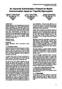
directional antennas which sufficiently suppress all reflected paths. Signal shadowing by obstacles is too high to be compensated by forward error correction (FEC) methods [11] and had to be handled by automatic repeat request or other higher layer protocol mechanisms. Clearly, rain attenuation at Ka-band is higher as compared to Ku- and C-band and thus one would expect a relatively low link availability. Furthermore, Fig. 3 shows that the rain attenuation in the uplink (30 GHz) is approximately twice as high as in the downlink (20 GHz). As rain attenuation appears only form time to time, adaptive FEC and modulation supports the efficient usage of the available bandwidth and transmitter power. This approach is feasible, since the maximum fade slope value for 0.01% of an average year is about 0.6 dB/s [4] which results in slow fading compared to a frame duration of 24ms. 10 Climatic zone: H Polarisation: circular
1
E: Elevation angle
0.1 Ka-band
0.01
30 GHz
Ku-band C-band 12 GHz 4 GHz E=40° E=40°
0.001 Percentage of time attenuation is exceeded [%]
0
5
10
15
E=20°
20 GHz E=20°
E=40°
20
25
30
E=40°
35
40
45
50
55
60
Rain attenuation [dB]
Fig. 3 Rain attenuation statistics for one year in climatic zone H (e.g. Europe) The system design includes three major FEC schemes: •
No FEC is applied to the payload. The ATM cells are merely guarded with a 32-bit CRC with a block length of 57 byte used for error detection,
•
Reed Solomon Code, RS(65,53) over GF 28 which can correct up to 6 byte errors, or
•
Rate 1/2 block turbo code concatenated with a RS(65,53) code.
Fig. 4 illustrates that even at a minimum elevation angle of 20°, the system can do without any FEC at all for most of the time. If we define link availability as the percentage of time that the ATM cell error rate (CER) does not exceed the required threshold value of 10-6, a simple CRC error detection scheme without any FEC correction methods results in a link availability of 99.15% (i.e. the link is not available for 72.7 hours per year). The RS(65,53) code applied to the ATM cell increases this availability to 99.80% and the concatenation of a block turbo code and RS(65,53) further improves the link to be available for 99.92% (limiting link failure to 7 hours per year). We use the availabilityburstlength product (ABLP) to compare the efficiency of this adaptive FEC scheme with a permanent RS(65,53) coding at QPSK modulation. The ABLP of this permanent scheme is 1.22 (= 99.8%*65/53). The adaptive FEC scheme has a higher availability of 99.92% and has nevertheless a lower ABLP of only 1.08 (= 99.8%*57/53 + 0.66%*65,53 + 0.12%*130/53). As all used codes are systematic, the uncoded block error rate of the information part can be used together with the measured received power to decide when to switch between the codes. With this kind of adaptive coding, high link margins that would have been required in traditional systems to reach high availability, are avoided and the saved margin can be used in rainless periods for higher data rates. As this proposed FEC scheme upholds the available data rate, the burst length has to be changed accordingly. Due to the burst time plan (BTP) broadcasted in each downlink frame, this change can be achieved on a frame by frame basis. Of course, if no more resources are available, the data rate cannot be uphold and the useful data rate has to be reduced. Bringing the idea of saving link margins one step further, one cannot only think of an adaptive FEC scheme but also of changing the modulation scheme for rainless periods and for high elevation angles. This approach is illustrated for a 8 QAM and 16 QAM modulation scheme in addition to the baseline QPSK modulation. Fig. 5 indicates that 8 QAM and 16 QAM can be used in rainless periods and at high elevation angles thus resulting in shorter burst lenghts of 0.72 and 0.54, respectively, without reducing the overall availability.
99,99
0,88 Block Turbo Code (rate 1/2) & RS(65,53)
CERth=10-6
99,97 99,93 99,90
2,63
RS(65,53)
99.92 % 7 h/y
6,13 8,76
no FEC
99.80 % 16.6 h/y
99,70
26,28 99.14 % 72.7 h/y
99,30 99,00
61,32 87,60
97,00
262,79
93,00 90,00
613,17 875,96 10
20
30
40
Elevation Angle [deg]
Hours per year link is not available
Availability [%]
Uplink Climatic Zone: H Polarisation: circular
Fig. 4 Uplink availability due to rain for an ATM CERth of 10-6
25
16 QAM
/h
m 0m
20
m
m /h
ES /N0 [dB]
2m
8 QAM
/h
m
10
16
S
m
0
/N E [dB]
/h
4
m
15
5
Burst length 0.54 0.72
QPSK
1.08
QPSK, RS(65,53)
1.23
QPSK, RS(65,53), Rate 1/2 Block Turbo Code
2.46
Uplink (30 GHz) E=20° E=40°
0 -8
-6
-4
E=90°
-2
0
2
4
6
8
t [min]
Fig. 5 ES/N0 for a satellite overpass at different rain intensities (in mm/h); required coding/modulation for an ATM CERth of 10-6 (error detection with 4 Byte CRC or RS(65,53) code) 4.
PROTOCOL IMPLEMENTATION AND TESTS
The designed protocol is (partially) implemented using the FreeBSD-5.0-current version [5] for testing and demonstration purposes. The implementation is modular in terms of separating a satellite channel emulation entity from the implementation of the MAC protocol and from the end-system itself. The implementation was used to conduct measurements with respect to the different FEC schemes, the effects of shadowing, and the usability of standard TCP in a variable delay, mobile user environment. 4.1.
Overview on Protocol Prototyping and Demonstration Environment
The MAC protocol is implemented using an integrated prototyping and demonstration environment developed by the satellite group of the competence center for advanced Network Technologies (CATS) at the Fraunhofer Institute Fokus. The environment is built based on standard, commercial of-the-shelf PC and ATM equipment as shown in Fig. 6 and consists in its core out of a wireless link emulation unit, the control station, and MAC protocol development units (denoted as data link control, DLC, and satellite DLC units; the DLC layer consists of the MAC and the logical link control, LLC) [6]. The wireless link emulation unit receives MAC packets from all user terminals (i.e. their corresponding DLC unit) and merges these packets into a single MAC frame which is afterwards forwarded to the satellite (SDLC). During this process, the wireless link emulation unit adds a variable propagation delay, corrupts received data according to a
Fig. 6 Prototyping and Demonstration Environment predefined error rate, and handles possible contention situations. Shadowing is implemented with a simple on-offmodel; the duration of each stage and the probability to switch from one to another is based on real world measurements done by the German Aerospace Center (DLR). All the functions of the unit are configurable via SNMP; its input may directly gained from analysis of the satellite system (using the satellite toolkit STK [7]). Ethernet is merely used to encapsulate the MAC frames in order to send them from one DLC system to another and has no effect on the MAC protocol itself. The control station initializes the wireless link emulator and the MAC protocol development units (SDLC and DLC). Additionally, it acts as an NTP server which is used by the link emulator and DLC units for local clock synchronization. The MAC protocol prototyping unit is used to implement the new protocol. As seen in Fig. 6, it is separated from the user terminal and can be physically considered as an external VSAT modem connected to any standard PC or workstation via ATM. As all other components, the DLC is a standard PC running FreeBSD-5.0-current [5]. It is equipped with an ATM interface (connection to user terminal) and two Ethernet interfaces (one used for management purposes, the other to connect the DLC with the wireless link emulator). The Netgraph concept of FreeBSD [8,9] allows the encapsulation of the entire MAC development, thus following a modular protocol design technique which enables space system engineers to build satellite communication systems out of standard components. 4.2.
Implementation Issues
As mentioned before, the DLC system is separated from the user terminal which results in a distributed protocol stack implementation. The new MAC (DLC) protocol is surrounded by several other modules as illustrated in Fig. 7 (next page). The interface to the user terminal consists of standard modules and interfaces, namely f/hatm and ng_atm. As the developed MAC protocol expects only a single flow of ATM cells, an additional netgraph module was designed to multiplex a number of incoming ATM connections (ng_mux). The physical connection to the wireless link emulator is a standard 3Com Fast Ethernet interface (xl) with its corresponding netgraph node ng_ether. The interface ng_SATtrans is simple encapsulation of MAC frames into Ethernet frames in order to forward them over standard commercial of-theshelf network components to the wireless link. This encapsulation has no effect on the functionality nor on the implementation of the MAC protocol. Finally, the entire MAC protocol implementation is hidden within the Netgraph module ng_dlc. It has three service access points (standard netgraph hooks), namely ATM SAP, UNI SAP, and PHY SAP. The first receives the multiplexed ATM cells which are tunneled from the user terminal to the DLC. The UNI SAP directly connects with the standard ATM node (ng_ATM). The latter directly forwards any control cells received on the reserved PVC to the DLC node. Finally, the DLC node has a Netgraph hook to the physical interface (PHY SAP). It may be connected to the actual driver for the satellite antenna or, as seen in this system configuration, to intermediate interfaces which emulate the physical channel [6,10].
4.3.
Measurements and Tests
The protocol prototyping and demonstration environment was used to conduct several measurements over the developed MAC protocol. Measurements ranged from mere ATM cell flow measurements up to the analysis of higher layer protocols, i.e. TCP/IP [11,12,13].
Fig. 7 DLC system structure 4.4.
Delay one cell per frame traffic
For this measurement the sending application was configured to send one ATM cell every 24 ms. This is the same as the frame rate on the wireless link, but since the application and the DLC layer use different mechanisms for timing, they cannot run synchronously. The DLC starts a 24-millisecond timer each time it starts to send the sync preamble. This means that any jitter in the timer will influence all succeeding frames. The application on the other hand computes the time to wait for the next cell depending on the start time of the application, the current time and the number of emitted frames. This means that the application will send at a rate of 24 ms (with regard to the local clock) integrated over some time, whereas the DLC will generally suffer from wanders in the clock. This can be seen in the results of the measurement. If both the application and the DLC were synchronous one would expect the delay to be the theoretical link delay plus a constant value between 0 and the length of the frame. Because of the asynchronism a more complex delay behavior is observed. The delay does wild jumps between the link delay and the link delay plus the frame time (24 ms) plus a small constant value. The reason for this is that a cell may arrive at the DLC when the DLC just begins its uplink burst or when the uplink burst has just ended. In the first case the cell will see no additional delay, whereas in the second case it will get an additional frame time (24 ms) of delay. The mean delay at any given time is:
d = dw + t f 2 + d p
(1)
where
dw tf
is the link delay,
dp
the processing delay.
denotes the frame time (24 ms), and
The measured one way delay between to end systems is shown in Fig. 8. The link delay varies between 9 ms and 18 ms (uplink plus downlink delay). The mean cell delay (averaged over 4 seconds) follows exactly the theoretical value. The processing delay is in the order of 4 ms.
4.5.
Measured application level error rates
For this measurement, a video traffic source is used, i.e a typical H.261 coding giving a 512kbit/sec CBR bit stream. We assume that at a 25 frames per second picture rate, the encoder emits packets of 63 cells which get shaped to a CBR stream (up to 3024 bytes per frame) [11]. The FEC coding schemes and the rain have been varied. One of the problems observed was that at an error probability of more than 0.2 the ATM signalling starts to break down and the user connections are released. This gives a very
Fig. 8 One cell delay (full period) strong limit for the usability. It must also be noted that for audio traffic the usability is lost with much lower error rates, while video may still be observable. Fig. 9 shows the measured packet (cell) error rates for various FEC coding schemes and rain intensities. Measurements have been done for CRC, RS and turbo coding for rain intensities of 6mm/h, 10mm/h and 16mm/h. If there is no curve for a given combination, than there have been no errors for that combination. 4.6.
Shadowing Effects
The effects of shadowing are described by an on-off-model. The corresponding state machine consists out of two stages: one in which traffic is received by a mobile user (direct line of sight to satellite) and one in which the entire traffic is discarded (shadowing situation). The transition probabilities between the two states are based on empirical data gained by German Aerospace Center (DLR) for an urban environment [11]. Measurements are conducted for a pedestrian walking at approx. 3m/s (Fig. 10) and a car driving in between 14m/s and 50km/h (Fig. 10). The cell loss rates show the limited usability of a Ka-band based satellite system for urban, mobile communication. While mere data transfer (no video / audio traffic) is still feasible for a pedestrian’s movement pattern, it is not feasible for car communication.
Fig. 9 Error rates for various codings and rain intensities
Fig. 10 Cell loss and delay caused by shadowing due to pedestrain’s movements
Fig. 11 Cell loss and delay caused by shadowing due to the movement of a car (14m/s – 50km/h)
5.
SUMMARY
The MAC protocol described in this paper was designed for an ATM-based LEO satellite system for multimedia communication. The proposed MAC protocol is adaptive in both: its TDMA frame structure with a movable boundary between the latter’s contention free and contention prone area, and its adaptive FEC schemes. While measurements show that switching between different FEC schemes can guarantee an acceptable cell error rate even under rain conditions of up to 10 mm/h, shadowing cannot be compensated in urban areas. Especially for large cities, supportive networking infrastructure, e.g. UMTS networks, are required to uphold continuous communication for moving users. REFERENCES [1]
H. Bischl, J. Bostic, M. Werner, M. Sabattini, H. Ernst, L. Richard, A. Dreher, H. Brandt, M. Emmelmann, F. Krepel, J.-J. Tchouto, C. Tittel, and P. Todorova. ATM-Based Multimedia Communication via LEO-Satellites – System Architecture Report. Oberpfaffenhofen, Germany: German Aerospace Agency (DLR), April 2000.
[2]
H. Bischl, J. Bostic, M. Werner, M. Sabattini, H. Ernst, L. Richard, A. Dreher, H. Brandt, M. Emmelmann, F. Krepel, J.-J. Tchouto, C. Tittel, and P. Todorova. ATM-Based Multimedia Communication via LEO-Satellites – Target System Report. Oberpfaffenhofen, Germany: German Aerospace Agency (DLR), October 2002.
[3]
H. Peyari. Medium Access Control Protocols for Space and Satellite Communications: A Survey and Assessment. Dent, Ohio, USA, Department of Mathematics and Computer Science at the Kent State University, Feb. 2003, Photocopied.
[4]
L. Castanet. Fade Mitigation Techniques for new Satcom Systems operating at Ka&V Bands. PhD Thesis, L’Ecole Nationale Superieur de L’Aeronautique et de L’Espace, Toulouse, December 2001.
[5]
(2003) The FreeBSD Homepage. [Online]. Available at: http://www.freebsd.org.
[6]
Marc Emmelmann. An Integrated Prototyping and Simulation Architecture for Space Specific Protocol Developments and Verifications. NASA 3rd Space Internet Workshop, June 4-6, 2003, Cleveland, Ohio, USA.
[7]
STK Homepage.
[8]
FreeBSD Manpage Netgraph(4), available online at http://www.FreeBSD.org/cgi/man.cgi; Internt; last assessed May 2003.
[9]
Archie Copps. All About Netgraph, Deamon News March 2000, http://www.deamonnews.org/200003/netgraph.html; Internet; accessed 07 April 2002.
[10]
H. Brandt, F. Krepel, and C. Titel. Multiple Access Layer and Signalling Simulator for LEO Satellite Systems. AIAA International Communication Satellite System Conference and Exhibition, May 12-15, 2002, Montreal, Canada.
[11]
H. Bischl, J. Bostic, M. Werner, M. Sabattini, H. Ernst, L. Richard, A. Dreher, H. Brandt, M. Emmelmann, F. Krepel, J.-J. Tchouto, C. Tittel, and P. Todorova. ATM-Based Multimedia Communication via LEO-Satellites – Final Report. Oberpfaffenhofen, Germany: German Aerospace Agency (DLR), December 2002.
[12]
Marc Emmelmann. Effects of advertised receive buffer size and timer granularity on tCP performance over erroneous links in LEO satellite networks,” in Proc. IEEE Globecom ’02, Taipei, Taiwan, Nov. 17-21, 2002.
[13]
Marc Emmelmann. (2002, May) Dimensioning of receive buffer size and timer granularity for optimal network performance of TCP in a variable delay LEO satellite network. NASA Internet Space Workshop ’02. [Online]. Available: http://siw.gsfc.nasa.gov.
available
online
at