An Adaptable, Cost Effective Image Processing System Jim Nichols
Dr. Michael Moore
Sverdrup Technology, AEDC Group
Measurement and Computing Systems Laboratory
939 Avenue C
Dept. of Electrical & Computer Engineering
Arnold AFB, TN 37389-9900
Vanderbilt University
[email protected]
[email protected]
ABSTRACT Non Destructive Evaluation (NDE) uses many data processing techniques to transform raw data or information from a specific NDE technique into useful NDE information from which decisions can be made. Historically, the data processing systems associated with each NDE technique were tuned or optimized to that technique . In today's environment it is desirable to quickly evaluate promising techniques while maintaining minimal manpower and/or capital penalties. In this paper, we discuss the result of a joint effort between Arnold Engineering Development Center (AEDC) and Vanderbilt University. The goal of this effort has been to apply modular Commercial Off-The-Shelf (COTS) hardware and advanced parallel software synthesis techniques to create a flexible and adaptable image data processing system. The culmination of this effort is the MIRTIS (Model-Integrated Real Time Imaging System). MIRTIS uses Model Integrated Program Synthesis (MIPS) techniques to automatically generate parallel software implementations of image processing computations, which are executed on a parallel hardware architecture built from COTS parts. The most significant difference between MIRTIS and traditional imaging systems is that the "programming interface" consists of a high-level, graphical specification environment. The user specifies the computations to be performed by drawing a graphical data flow representation consisting of boxes (algorithms) and interconnecting lines (communications). The performance requirements of the application and the topology of the available hardware network are also specified graphically. These graphical specifications (models) are used by MIRTIS to generate the necessary parallel software configuration to implement the computation at the specified performance. In addition to implementing data flows made up of standard image processing algorithms, the user can also expand the functionality of the system by adding new algorithms to the support library. The algorithms are implemented as normal “C" subroutines and are fully integrated into the system by specifying pertinent information in terms of an algorithm model. MIRTIS was initially designed to support the demands of the real-time image processing domain, but is currently being extended to support applications which operate on very large data sets (ex. Computed Tomography (CT)), but which do not necessarily require real-time performance. The approach will produce a system which is programmed graphically, but which will generate high performance parallel implementations of a large class of imaging computations. This will greatly enhance the capability to quickly and rapidly generate imaging systems customized for NDE support.
1. INTRODUCTION Many data processing techniques have been used to transform raw data or information specific NDE modalities into useful NDE information from which decisions can be made. While initially the techniques were based on programs running on general purpose computers, as systems were fielded, customized hardware (HW) / software (SW) systems were created to support timely decision making. As the HW/SW systems became more “tuned” for higher performance, the end user became more limited on trying new techniques from related disciplines for enhancing the data (ex. using medical x-ray enhancing techniques on industrial or aerospace x-ray NDE applications). The ease and complexity associated with making changes many times depend on the system that one inherits with a facility or purchases to support an effort. At one extreme lie systems for which the addition of new algorithms requires a new consulting contract with the vendor supplying the system. At the other extreme lie COTS-based NDE systems to which new algorithms can be added, but only after the user becomes very familiar with the underlying HW/SW system architecture and has mapped the algorithm to that architecture. The resources (skills / man-hours) required to do this are sometimes difficult to justify within a tight budget. While a facility which must follow a tightly structured procedure for material or part acceptance may not need this. Facilities like AEDC are increasingly needing to “push the envelope” to improve the quality of the NDE information being extracted and provided to our internal and external customers. While historically one might support one or two NDE techniques, now an NDE group might support many techniques like ultrasound, x-ray, thermography, laser-based techniques, etc., which require support of additional data processing techniques. With declining budgets, this higher level of support needs to be carried out by fewer people dedicated to the effort including programmer support for our data processing systems.
While the computational hardware elements have gone down in cost since AEDC started its joint effort with Vanderbilt University, the software and algorithm complexity has not been diminished while the availability of programmers has. The approach described in this paper has simplified the process of supporting new processing techniques for real-time image processing for the enhancement of x-ray, low-level light, and thermography camera image data. The model based approach used in the MIRTIS is now being expanded to support the rapid processing of 10,000 by 10,000 by 12 Bits/pixel images from 70 mm film digitization. These techniques could easily be adapted to CT image processing or other modalities that have large data sets. While the MIRTIS system has primarily been focused on imagery data, there are similar systems based on model integrated technology in use at AEDC (CADDMAS), NASA Marshall (engine monitoring), and NASA Stennis (engine health monitor) that process 1-D data streams while monitoring turbine engines & rocket engines. The MIRITS system is composed of COTS or in-house standard COTS format TIMs (Texas Instruments Module) and can be readily scaled from a few to a large number of processors. The largest system built to date contained 51 processors and was benchmarked at 520 MFlops sustained throughput while performing a complex edge detection on live video (counting only useful operations). However, the authors believe that by using more up to date processors, MIRTIS can scale up to 10 GFlop sustained range (while actually solving useful NDE problems). Because the run-time kernel was designed to introduce minimal communication and computation overheads, the constraints on the scaling are governed more by how many processors can be realistically packaged into a chassis and powered than by the parallelism of the software. 1.1. Image Data Volume Digital imaging applications require huge computational performance due to the large data sets involved. NDE applications, which utilize on–line video processing, require sequences of images to be processed in real-time. Image sequences of typical resolutions vary from 512 X 480 or 640 X 480 (typical industrial / home quality video) to 720 X 486 (D1 & D2 broadcast quality video) pixels. Such sequences at standard frame rates (30 frames/sec) and 256 level gray scale (8 Bits/pixel) represent a data rate of 8.8 to 10.5 Megabytes per second. Color sequences (24 Bits/pixel) at the same pixel resolution produce a 26.4 to 31.5 Mbytes/sec data rate. Generally, imaging sensors used in many NDE applications are based on COTS video (RS-170) cameras. As the High Definition Television (HDTV) standards drive the COTS market for high definition cameras and recording systems the image sizes and data volumes could quadruple in the near future. When these increasing resolutions become available many of the existing dedicated hardware solutions that have served the RS-170 resolution systems will have to be replaced. This potential data volume increase coupled with the need to adapt processing algorithms requires more flexible, scalable real–time image processing solutions than are currently available. A more generalized and flexible approach toward system development is needed in order to support such applications. 1.2. Image Processing Computation Costs Typical image processing and enhancement applications require on the order of hundreds or even thousands of operations per pixel in order to enhance, segment, and extract features from image sequences, which translates into a demand for tens of Giga-operations per second[1,2,3]. Even less computational intensive applications, such as video enhancement, can require hundreds of Mega-operations per second. Moreover, it has been estimated that future applications, such as dynamic scene or image sequence interpretation, may require on the order of hundreds of Giga-operations per second. Hardware architectures consisting of a single general-purpose processor are incapable of delivering these levels of computational performance. Due to these high performance needs, most successful applications of real–time imaging have by necessity been built from custom hardware designed to perform fixed sets of specific image processing algorithms. Although such specialized hardware solutions have met computational requirements of some Real-Time Image Processing (RTIP) applications, there are many drawbacks to this approach. Hardware implementations are expensive, and real–time performance is achieved by sacrificing end–user programmability and flexibility. 1.2. Parallel Image Processing The most obvious alternative to avoid custom hardware is to parallelize the computations and map them to a scalable parallel hardware architecture made up of COTS components. Image processing algorithms have inherent concurrency that is relatively simple to exploit [4]. The idea of parallelism is certainly not new. Papers describing parallel architectures, algorithms, kernels, programming models, compilers and software generators abound in the literature. There have been many parallel hardware architectures boasting incredible numerical benchmarks, and there have been instances in which parallel implementations have been successfully deployed in real applications. However, the inherent difficulty of programming parallel machines has limited the number of cases in which programmers without parallel processing expertise have successfully and cost–effectively exploited the technology in real–world applications. It has become clear that developing a general parallel image processing system involves much more than building a high performance parallel hardware architecture or a parallel language. Some of the most difficult problems lie at the systems level, including the hardware, software, and their relationships. Without high–level programming
environments and tools designed for building parallel systems, exploiting parallelism in real world image processing applications is, in most cases, not the most cost–effective or practical approach. An environment and framework for building parallel image processing systems is needed. It is crucial that this framework be system–centric, simultaneously addressing the parallel hardware, parallel software, and integration issues. The goal is a system with which programmers without parallel systems expertise can generate real–time parallel software implementations using the parallel hardware architecture available to them. The system should insulate the user from the underlying parallel implementation details, while achieving the high performance of specialized hardware solutions, and retaining the generality, flexibility, and ease of use of uni–processor software systems. This paper presents an approach toward this goal. By using MIPS techniques and by taking advantage of the natural concurrency present in image processing computations, real-time parallel image processing systems can be automatically synthesized from high–level system specifications. The most difficult issues that usually inhibit the cost-effective use of parallelism are decomposing the software into communicating sub-computations, mapping the sub-computations to the available resources, and implementing the inter-processor communications, all in a way that produces predictable, reliable performance. The aim of applying MIPS to the parallel imaging domain is to effectively render the complex details inherent to parallel software development transparent to the programmer by automating these difficult tasks. The MIPS approach promises to lead to the cost–effective exploitation of parallel hardware architectures for building more flexible, powerful, and cost-effective imaging systems than are currently available. The Model Integrated Real–Time Image Processing System (MIRTIS) is a demonstration of this concept. MIRTIS was developed for processing video in real–time and processing very large archived data sets off-line [5-8]. It employs the Multigraph Architecture (MGA), a framework and set of tools for building MIPS systems [15], to generate image processing applications which run under the control of a parallel run-time kernel on a network of Texas Instruments TMS320C40 (C40s) Digital Signal Processors (DSP). The run–time system is configured automatically from graphical models declaring (1) the computations to be performed, (2) the C40 network configuration, and (3) the performance constraints of the target application. The automatic configuration is performed by the MIRTIS model interpreter, which analyzes the models to determine the feasibility of a real–time implementation, and if a solution is feasible, parallelizes, scales, and maps the given computations to the resources such that the real–time constraints will be met. It also configures a graphical user interface with which the user can adjust processing parameters dynamically as the system runs.
2. BACKGROUND This section provides a brief description of the class of imaging applications considered, and the issues involved in designing, implementing, and maintaining systems for supporting these applications. 2.1. Image processing computations Image processing is related to the larger field of computer vision. Computer vision systems process data acquired from image and other sensors, which detect visible, infrared, or even magnetic radiation, and attempt to construct some model of the surroundings which may be used in formulating controls over the environment and/or presented for human interpretation. The early vision steps are made up largely of algorithms that operate on image data and produce images, transformations of images, or simple data structures describing images. These image processing algorithms are sometimes referred to as low level vision [9] because the role they play is to pre–process images for transformation into symbolic data (edges, connected components, etc). Because applications from the video processing domain have driven the effort, the emphasis has been placed on image processing systems which are persistent. Persistent systems do not execute and terminate, but execute continuously, computing sequences of result data structures from sequences of input images. This motivates the extension of the genre of image processing algorithms from those which operate on images to those which operate on image streams, or even volumes. 2.2. Image processing data flows A popular method of building up image processing applications is to combine several pre–coded algorithms together to form a Large Grain Data Flow (LGDF). A LGDF is a directed graph in which the graph nodes represent processing blocks and the arcs represent communication between the blocks. The LGDF style specification is commonly used in signal and image processing. One reason is that its visual nature promotes the integration of high–level graphical programming interfaces. For example, Khoros[10], a popular image processing development environment from the University of New Mexico, provides a visual programming interface in which data flow graphs are drawn to specify the computations. Khoros performs the control flow and transfer of data between the computation blocks automatically as it executes the data flow.
In keeping with this approach, the problems considered are LGDF computations made up of image processing algorithms. The following restrictions are placed on the data flow: (1) It must be a Synchronous Data Flow (SDF), which means that for each computation block, the amount of data consumed and produced each time the block runs is fixed [11]. (2) It must have no cycles (loops in the data flow graph not containing a delay element). (3) It must have no fan-ins (connections merged together), but Fan- outs (connections with multiple readers) are allowed. These computations are synchronous image processing data flows. 2.3. Real–time image processing Real-time image processing systems (RTIP) interact with (and are embedded in) their environments, and thus must produce outputs that are not only numerically correct, but which also meet timing constraints necessary for these interactions. The relevant environmental interactions for image processing systems are receiving data from sensors or other systems, and outputting data to displays, devices, or other systems that may apply controls to the surroundings directly (e.g. a vision system might generate controls for a robotic arm). 2.3.1. Relevant timing constraints RTIP systems may be required to service the input devices as quickly as the data is produced, produce outputs at a sustained rate, or produce an output from each particular input within a constrained amount of time. The two relevant types of temporal constraints in real–time image processing systems are: •
throughput: the rate at which results are produced by the system, usually quantified in (frames/sec) for video based systems
•
latency: the total time between the sensing (or reading from a file) of a particular image and the results of that image leaving the system, usually quantified in seconds, and sometimes in frames.
It is important to note here the difference between high performance systems and real-time systems. Real-time image processing systems must not only support the large I/O data rates and computational power discussed previously, but the performance must be predictable and controllable. It must be known a priori to run-time (1) if a computation can be done within the timing constraints on the available hardware, and (2) if so, how to utilize the hardware to achieve the required performance. Thus, predictive models of both throughput and latency are necessary. Since it is generally difficult to accurately characterize the performance behavior of a computation, the models must be developed using knowledge of the algorithms and the underlying run–time system. 2.4. Specialized real–time hardware solutions The approach traditionally taken in supporting real– time imaging has been to implement the most commonly used computations in specialized real– time hardware. Hardware implementation has been the most practical and cost– effective solution that could meet the performance requirements of RTIP. There are many commercially available machines that perform various sets of standard image processing computations at real–time rates (e.g. Matrox, Coreco, DataCube). Some are more general and flexible than others. However, no hardware solution provides all of the following:
Image Processing Data Flow
Parallel Processing Data Flow
Graphical Data Flow
Parallel Software Version of Data Flow
Decomposition Scaling of Data Flow
•
Programmability/Extensibility: Existing Runtime Implementation hardware solutions are either not end–user programmable, offer limited programmability, or are programmable at a high resource cost (labor and expertise). Adding functionality may require costly VLSI design or reprogramming of the Field Programmable Gate Arrays (FPGA). It is not practical for the user to invent and experiment with non–standard algorithms. As Figure 1 - Parallelizing Image Processing systems such as Khoros have shown, the ability Computations to rapid–prototype and experiment with algorithms for the application at hand can greatly enhance the ability to generate effective solutions.
•
Flexibility: The data paths are either hard-wired or have a fixed number of configurations, so the possible ordering of the computations is often limited.
•
Scalability: More computations or higher performance cannot always be achieved by adding hardware.
•
Ease of use: Existing hardware solutions are difficult and expensive to use. Learning to use specialized hardware systems can require months of training, even for experienced image processing experts. The steepness of the learning curve is a major factor in the economics of computer solutions, since labor is traditionally more expensive than hardware.
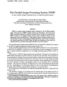
The use of specialized real–time image processing hardware has proven successful for some applications. However, the inherent limitations have caused the real-time imaging industry to develop the mind-set of trying to fit problems to the fixed capabilities of the available real–time hardware, instead of building integrated solutions to the problems at hand. This has had the unfortunate effect of placing a barrier between the algorithm development community and many real-world embedded applications. Since it has not been feasible to create real–time implementations of new, non–standard algorithms to use in embedded imaging systems, much of the theoretical image processing developments have not been used in embedded applications. 2.5. Parallelizing image processing computations Instead of using hardware implementations, a more flexible approach is to generate parallel software version of the computations and map them to a distributed memory multi–computer, as is shown in Figure 1. Because the operations have characteristics that make them particularly suitable for implementation on parallel computers, image processing has been the most common area for the application of high performance parallel computing.[4,12] Then why are most commercially available image processing systems not parallel software systems? The answer is that the parallelism adds complexity to tasks of writing software and integrating systems. The added complexity translates into higher implementation and integration costs. For applications with relatively fixed requirements, specialized hardware systems provide adequate flexibility and performance. Specialized hardware systems have provided a more cost-effective solution because of the high costs of developing parallel software with traditional methods. However, for many of the current and near future applications (such as those mentioned above in the introduction), the requirements vary widely depending upon many factors. The solution must be highly adaptable and extensible to the particular situation at hand. Parallel software systems, being more flexible, are more appropriate for these applications. To cost-effectively support these applications will require the development of methods and tools for implementing and integrating parallel software imaging systems that automate the difficult parallel system integration tasks. The first step in this development will be to examine how image processing computations can be parallelized and mapped to parallel architectures, and where the complexities lie. The basic parallel computing organizational concepts that best support the characteristics of image processing computations are data–parallelism (spatial decomposition or temporal decomposition) and functional parallelism. These parallel processing constructs and how they can be exploited in image processing are discussed next. 2.5.1 Spatial Decomposition Many image processing algorithms are easily data parallelizable by decomposition of the data in the image plane. A simple data parallel programming technique which is applicable to image processing is the split-and-merge model.[4] In this technique, each input data structure is split into N pieces, which can be blocks of rows, blocks of columns, panels, overlapping regions, etc. The pieces are distributed across the memories of the N worker processors, each which performs the same algorithm on its sub–section of the data. The partial results are then merged to form the output. Since each of the workers computes 1/Nth of the result concurrently, the per image computation time is reduced by a factor of at most N. This has the potential of both reducing latency and increasing throughput when executing on image sequences. However, the acceleration actually achieved depends upon the overheads introduced by the decomposition. Sources of overhead in the split-and-merge processing model are (1) splitting inputs: distributing the image pieces to the processors, (2) merging outputs: communicating the partial results and combining them, and (3) sharing data: communicating shared data and partial results between worker processors. How the data is to be split, shared, and merged depends upon the algorithm’s data access patterns. 2.5.2. Temporal decomposition Algorithms that either cannot be decomposed spatially, or for which the resulting gains would minimal, can still be successfully data parallelized when operating on image sequences by taking advantage of the sequence structure. Image sequences can be decomposed temporally instead of spatially (split the data along the time domain, instead of the spatial domain). Instead of images being distributed spatially, the pieces of the image sequence (entire images) can be distributed across the N processors in a round-robin fashion. In this case, each worker processes an entire
image, so there is no decrease in the time it takes for any one image to be processed (latency). However, images will be processed concurrently, so the throughput can potential increase by a factor of at most N. 2.5.3. Functional parallelism Functional parallelism takes advantage of the natural concurrency of a computation. The computation is broken down into semi-independent communicating sub-computations. The sub–computations along with the data passed between them form an implicit data flow computation graph. The application of functional decomposition to parallelized LGDF computation is straight–forward. N sub– computations can be executed concurrently on N processing elements, with data being transferred between the computations via inter–processor communication. The performance gains of functional parallelism are achieved through allowing the sub–computations to execute concurrently, and are controlled by the structure of the data flow and the allocation of processes onto processors. The speedup is bounded above by N, and the efficiency, (speedup/N), is affected greatly by the relative complexities of the sub–computations as well as the communications overhead. Unless the sub–computations are of similar complexity, the system is not load balanced, which results in the inefficient use of the parallel resources and poor performance gains. 2.5.4. Hybrid parallel constructs It is reasonable to combine these approaches and form a hybrid parallel construct which uses two levels of parallel decomposition, the top data flow level being functionally parallel, and the underlying sub-computations being data parallel (see Figure 2). Scaling and load balancing to the target throughput can be achieved by scaling the data parallelism of the sub–computations independently until each achieves the target throughput. This type of hybrid parallel construct can be applied automatically to data flow computations if methods of automatically data parallelizing and scaling the sub– computations are developed.
Figure 2 - Two Level Decomposition
3. Approach The approach taken in this work has been to use MIPS techniques, specifically the Multigraph Architecture, to generate parallel software versions of synchronous image processing data flows made up of sequentially coded algorithms, and automatically scale and map the resulting decomposition to a parallel hardware architecture. This section provides an overview of the approach taken toward this automatic decomposition, scaling, and mapping. Then it introduces MIPS and the MGA, and how MGA is used in automating the parallelization decisions. 3.1. Data flow decomposition and allocation to hardware
Block Route Input Regions
Route Partial Results
...
... ... ...
The data flows are decomposed using the two level hybrid parallel construct discussed in the previous section. As is shown in Figure 2, the data flow is first partitioned into computation blocks. Each block is then decomposed using either spatial or temporal data parallelism. Scaling (assignment of a number of processors to each block) is performed with the use of performance models constructed with a priori knowledge of the algorithms. Referring to Figure 3 note that Block has been decomposed using spatial data parallelism, and assigned a scaling factor of 3. The data parallelism has been implemented by making 3 replicas of the computation in Block, which have been allocated to 3 processing nodes in the hardware architecture.
t-3
t-2 t-1
t
... Schedule Block Data Flow
Figure 3 - Implementation
t
3.2. Difficulties Nothing has been said yet of how the implementation, including the control flow and communication, is supported. Moreover, the decision making processes for selecting the types of parallelism, the scaling factors, and the allocation of the decomposed data flow to the processing nodes have yet to be discussed. At this point is where the concept of developing a system becomes most important. The difficulty lies in that fact that the task of decomposing the algorithms, supporting the inter-process communication, providing control flow (synchronization and scheduling), figuring out to how many and to which processors the computations should be allocated, and determining how to route the communications through the communications network are inter–related. Some of these problems are difficult to solve even when considered alone. For instance, the general assignment problem is NP–complete.[13] The following interrelated problems must be solved simultaneously (assuming the partitioning has been done): •
Decomposition of blocks: select a parallelization method for each block of the partition.
•
Scaling blocks: select the number of processor for each block to load balanced and meet timing constraints.
•
Allocation: assign the decomposed, sub–computations of the scaled data flow to the available processors.
•
Communications routing: determines the path along which the communications will flow. For instance, each of the lines representing communication in Figure 3 must be routed somewhere through the hardware network.
•
Formation of performance models: determine accurately the performance that will result from a particular decomposition and mapping of a computation to the available resources. .
•
Support of parallel execution: provide the scheduling, communication, and synchronization to support execution of the data flow.
A major obstruction to automating the decomposition, scaling, and mapping processes is that these tasks are inherently inter–dependent. Note that the construction of performance models, which are used in making the parallelization decisions, requires knowledge of both the run–time system and the allocation of computations and hardware nodes. However, as figure 2 shows, the allocation is done after the parallelization decisions have been made. Performance models can not be built without taking into account the allocation, and vice versa. Because of these inter-dependencies, the general problem of mapping image processing synchronous data flows to arbitrary multi–computer networks while simultaneously guaranteeing that throughput and latency constraints are met has no closed–form solution. Moreover, performing an exhaustive search of all decompositions and allocations until the constraints are met is not a practical alternative because the search space is too large. The approach toward automatically mapping the computations to the resources must be to reduce the size of the search space by developing simplified decomposition procedures and allocation techniques which exploit the capabilities of the target hardware architecture and favor the properties of the majority of the applications. This is the approach taken in the MIRTIS system, as will be discussed in the next section. First, however, a short introduction to model–integrated program synthesis and the Multigraph architecture is in order. 3.3. Model–integrated program synthesis overview MIPS is a method of synthesizing software systems from high-level models. MIPS is related to code generation performed by compilers, but the goal of MIPS is not the generation of machine code. MIPS systems generate instead either code to be executed on a virtual machine, or a configuration of existing computations. Common to all the various existing MIPS approaches is a component called the model interpreter, which actually performs the program synthesis. The model interpreter transforms high-level system models, specified in terms of a paradigm, or language, into the system program.[13] 3.4. The Multigraph architecture The MGA is a MIPS architecture developed at Vanderbilt University which provides a frame–work and tools for (1) 14 building graphical domain specific models and (2) transforming the graphical models into executable applications. By using user problem domain specific models and interpreters, MGA allows the domain experts to specify a system in familiar terms without dealing with the underlying software engineering details, The MGA consists of the following components: (1) A graphical model builder (GMB).-this is a graphical environment in which domain specific models are built and manipulated. The current MGA model builder is called XVPE. (2) A model database for storing the models. The current implementation uses a public domain Object–Oriented DataBase (OODB) called obst. (3) Problem domain specific model interpreters, which translate the system models into the various components of the target system. (4) Integrated applications make up the target software system. (5) The run-time kernel, application
libraries, and/or operating system platform together form the run-time environment. For more detailed information about MGA, refer to [15]. 3.5. MGA models The models are built and manipulated via the XVPE graphical model building environment. XVPE is configured with a user specific problem domain specific modeling paradigm, which contains the concepts particular to the application. The modeling concepts available in the MGA system include attributes, parts, hierarchy, connection, association, reference, and multiple aspects. This set of modeling concepts has been shown to be rich enough to support the needs of a large and diverse set of problem domains[16…20].
4. MIRTIS 4.1. Overview MIRTIS is an MGA–based realization of the ideas that have been developed in the previous sections. It uses a combination of automatic program translation and meta–level driven software synthesis to automatically parallelize image processing data flows made up of sequentially coded algorithms. The parallelization decisions (types of parallelism and scaling factors) and the allocation of the decomposed data flow to the parallel architecture are performed automatically. The decisions are driven by the real–time constraints, which are modeled explicitly. It was determined that the decomposition and allocation algorithms should be simplified in order to decrease the search space of data flow to network mappings, and to make the automatic mapping of processes to processors a practical endeavor. The simplification in the mapping algorithm was made possible by adding complexity to the run– time system. Specifically, a special communication technique was implemented for the C40 which enables all communication to be routed along a hardware pipeline. The run–time system was kept semi-architecture independent by implementing the communication components as a separate layer which can be re–implemented for new hardware architectures, thus allowing the re–use of a large part of the implementation. Both a prototype C40 run–time system and the resulting mapping algorithm have been designed and implemented for this work. The special communications routing support in the run–time system reduced the complexity of the mapping algorithm significantly, making the interpretation process more feasible. 4.2. The MIRTIS architecture As is shown in Figure 4, the MIRTIS architecture follows the MGA framework. The system consists of (1) the Image Processing Description Language (IPDL) model building environment, (2) a model database, (3) the MIRTIS model interpreter, (4) an image processing application library, (5) the Pipeline Cut-Through (PCT) – C40 run–time system, (6) the MIRTIS graphical user interface, and (7) a network of C40s. The most important aspects of these elements are discussed next.
XVPE IPDL Model Editor Model Database MIRTIS Model Interpretor
4.3. The IPDL modeling paradigm The MIRTIS modeling paradigm, called Image Processing Description Language (IPDL), was designed specifically for real-time image processing. The concepts were developed by extracting the set of information required to support the automatic decomposition and mapping approach outlined in the previously. This section will briefly describe the paradigm, putting emphasis on the novel concepts. IPDL contains three types of graphical models, Signal Flow, Hardware, and Constraints, which represent the data flow computation to be performed, the hardware resources available for the solution, and the timing constraints required by the solution, respectively. The combination of a Signal Flow Application model, a Hardware Network model, and a Constraint model together form the specifications for a real–time image processing system.
Pipeline Cut-Through Decomposed & Scaled Image Processing Data Flow
MIRTIS Graphical User Interface| Configuration
PCT Network Configuration Files
MIRTIS Graphical User Interface
PCT Run-Time System
Image Processing Application Library
Video Out
Video In TI C40 Network
Figure 4 - MIRTIS Architecture
4.3.1. Signal flow models Signal flow models specify the image processing computations to be performed. The two types of signal flow models are applications, and algorithms. Applications are simply data flow graphs made up of algorithm models, each which declares pertinent information about an algorithm in the image processing library, such a how the algorithm accesses data in calculating its output data structures, and performance on the algorithm (benchmarks) the target hardware architecture. For a detailed description of IPDL see [7]. 4.3.2. Hardware and constraints models The Hardware models represent the computational resources available to implement the system. These contain information about the parallel configuration, such as network topology, resources available on each CPU, location of I/O resources, etc. The types of hardware models are Nodes (eg. C40s) , HostNodes (PCs or workstations), and Networks. Constraint models contain explicit declarations of the target latency and throughput required for an application. Throughput models have a numerical attribute specifying frame rate in throughput terms(ex. Video frames per second) and latency models have attributes specifying latency in frames. Both throughput and latency models have attributes specifying whether it is a hard or soft constraint. As will be seen, this attribute is used in the interpretation procedure in the case that the constraints cannot be met exactly. It specifies whether that constraint can be relaxed to allow a best effort implementation on the available hardware. 4.3.3. The MIRTIS graphical editor
The IPDL models are built and manipulated via a Graphical User Interface (GUI) that is intuitive and easy to use. The original version of the system used an X-Windows based editor called XVPE, but the current effort to generalize the MIRTIS is migrating the system to a newly developed PC Windows Microsoft Foundation Classes (MFC) based editor called GME. A view of GME can be seen in Figure 5. Not only is GME more usable, but it also stores the models as OLE containers instead of storing the models in the obst object oriented database. Without the requirement of an object oriented database, the new MIRTIS editor and interpreter will be able to be run on most any machine. 4.4. The PCT–C40 run–time system
A real–time image processing kernel called PCT–C40 has been implemented which provides run-time support for spatial and temporal data parallel execution of image processing synchronous data Figure 5 - MIRTIS GUI flows on pipeline–connected C40 networks. The kernel runs on each C40 node and performs the scheduling, communication, and synchronization necessary for data parallel computations. The scheduler on each node runs a Periodic Admissible Sequential Schedule (PASS)[11] that implements the synchronous data flow local to that node. The kernel configures and starts the PCT communication engine, which, in cooperation with the neighboring nodes, distributes the input data appropriately across the processors and combines the local results to form the output data. Since the computation and communication schedules are static, the scheduler introduces minimal run–time overhead. This also has the effect of simplifying the kernel by pushing the work of generating computation and communication schedules into the model interpretation process. 4.4.1. Pipeline cut–through overview Pipeline Cut-Through (PCT) is a communication technique that allows synchronous data flows parallelized with the spatial or temporal data parallel constructs to be mapped to a group of C40s connected in a sequential copmputational grouping called a pipeline (a PCT group). PCT achieves computational organization by routing all communications, including the distribution (splitting) of input data and the collection of partial results (merging), along the C40 pipeline (see Figure 6). PCT also provides coordination between the communication and computation processes. Since PCT implements the parallel facilities automatically, the data parallelism is absolutely transparent to the programmer. Each node of a PCT group performs the same computations on a different section of the image data. The incoming stream is split and spread across the memory banks of the group nodes, and after the local data flow computation
has produced the partial results, they are merged to form the output data stream. As well as splitting and merging the data stream, the communication engine also supports the sharing of regions of the input sequences between two or more nodes in a PCT group. For more information about PCT, see [5-8].
Required Regions Derived From Data Dependency Specifications
Block
Schedule Algorithms of Block Data Flow On Each Node
... ... ... t-2 t-1
t
Route All Communication Along The Pipeline
t
Figure 6 – PCT Runtime Support 4.5. The image processing library The actual image processing functionality is provided by a library of image processing algorithms written in C and compiled with the standard Texas Instruments C40 compiler. This library is the simplest component of the system, since the image processing functions can be written as if they were to be used in a normal uni–processor system. It was decided to take this approach instead of generating the image processing specific code directly from the models so that image processing libraries optimized for the target architecture could be re–used, which saves time and results in better resource utilization. 4.6. The MIRTIS interpreter The model interpreter is the heart of any MGA system, and requires the largest implementation effort. The job of the MIRTIS model interpreter is to translate the IPDL models into a decomposition of the data flow, scale and map the decomposition to the underlying hardware architecture, and construct network communication and computation schedules which configure the real–time image processing kernel and realize the parallel real–time computation. Referring to figure 4, the products of the interpretation are (1) PCT network configuration files, and (2) a GUI configuration file. These files are used in (1) booting the network, (2) configuring the network communication engines and schedulers, and (3) configuring the dynamic parameter graphical user interface. 4.6.1. Relationship between performance models and allocation Performance models are needed for determining (1) if a particular computation can meet the specified performance goals using the available hardware, (2) a decomposition method and granularity of parallelism (scale) for each block, and (3) a mapping of the decomposed computations to the hardware that will meet the constraints. In general, performance models are dependent upon the properties of the particular computations, the parallelization technique, and the allocation to the hardware network. This forces the processes of decomposing the data flow and allocating the data flow to the hardware to occur simultaneously. It is preferable to decouple these processes to make the mapping more practical to automate. Due to the properties of the PCT communication technique and the support provided by the PCT run–time system, the allocation scheme and hardware topology can be simplified enough that the throughput and latency models can be built in a separate step before allocation. This effectively decouples the decomposition and allocation processes, making the automatic mapping of data flows to hardware tractable. The emphasis in developing performance models can thus be placed on the properties of the computations. See [7] for a complete development of these models. 4.6.2. The interpretation procedure The decomposition and allocation processes can be made independent by assuming that the PCT run–time system will be used, the search for an appropriate mapping between the image processing data flow and the hardware pipeline can be reduced to finding an appropriate partition of the dataflow, and choosing a decomposition alternative (a supported type of parallel decomposition) and a scaling factor for each PCT Block. The success of a particular decomposition involves building throughput and latency models and comparing them to the throughput and latency goals specified in the system’s RealTlmeConstraints model, then making sure that the
hardware architecture can support the decomposition. Enough of the appropriate type of processors must be available, and they must be connected in an appropriate topology. The procedure followed by the interpreter is to first partition the synchronous image processing data flow such that it is compliant with the PCT run–time system (see [5-8]). Then a search is performed for a combination of block decomposition alternatives and scaling factors that will meet the performance constraints and that the hardware architecture can support. The interpretation algorithm performs an exhaustive search of all decomposition alternative combinations until either the constraints have been met, or the valid alternative sets have been exhausted. Alternative combinations that meet the hard real–time constraint (s), but may not meet the other(s), are stored during the search. The end result of a successful search is a partition, and a set of decomposition alternatives and scale factors for the partition blocks that can be allocated to the hardware pipeline to achieve the target throughput and latency. If no solution is found during the search, an attempt is made to relax the throughput and/or latency constraints. If both constraints are hard constraints, then no concessions are made. Otherwise, the alternatives that were stored during the search are examined and the one that most nearly matches the hard constraints is chosen. The decision of which of these most nearly matches the constraints is made by putting priority on throughput by choosing the set which produces the highest frame rate. This decision was made primarily because the system was designed with real–time video in mind, and in video applications throughput is most often the more important constraint. The allocation occurs only after a scaled decomposition has been chosen for the solution. This decoupling of the decomposition and allocation was made possible by first partitioning the data flow and using the PCT run–time system. Without this simplification, the performance models would be inextricably dependent upon the allocation, and thus a much more complicated procedure would be required.
5. CONCLUSIONS This work has begun to address the problems which must be solved to support the current and future NDE image processing applications. Some more involved image processing applications may require on the order of billions of operations per second to support real-time applications. The work has taken a novel approach toward parallel programming by generating parallel real–time implementations of image processing data flows from high–level specifications. The implemented system includes a graphical environment with which the user builds visual models of the data flow computation, the hardware resources available to solve the problem, and real–time specifications of an application (figure 6). A model interpreter automatically transforms these models into a configuration of a real–time system that executes the modeled computation. The interpreter performs the data flow decomposition, performance modeling, scaling, load balancing, and scheduling automatically, then allocates the decomposed, scaled computation to a network of DSPs. A parallel image processing run–time kernel provides communication, routing, scheduling, and synchronization for the implementation. The current system can process incoming video data in real-time, process data from a system disk in non real-time, and in the near future, MIRTIS will support web based interaction using the MIRTIS Video system as a web-based image Monitor compute server (figure 7). Although the mapping requires knowledge about the underlying run–time system, the Data Data applications are specified in terms of high-level models. Figure 7 - MIRTIS Utilization Options This approach, supported by the MGA architecture, results in a level of architecture independence that will allow much of the system to be re-used when the target hardware platform evolves with the availability of faster and cheaper hardware. Presently the system is being extended to support C44 TIMs along with C40 TIMs. Future plans call for inclusion of TI 320C6x TIM modules (~1.5 Billion Operations/sec) and Field Programmable Gate Arrays (FPGAs) to perform more involved real-time calculation and data reduction processing. The integration of these new types of hardware will require changes in both the underlying runtime system and the interpretation procedure, but we expect that these changes can be achieved through extensions of the existing system as opposed to totally new efforts.
ACKNOWLEDGEMENTS This work was partially supported by the AFOSR/AFMC, US Air Force, contract number F49620-94-C-O076.
REFERENCES 1.
C.. Weems et al., ``The DARPA image understanding benchmark for parallel computers; Journal of Parallel and Distributed Computing 11, pp. 1-24,1991.
2.
C. Weems et al., ‘The parallel processing benchmark,” IEEE Journal of Parallel and Distributed Computing , pp. 673-688, 1988.
3.
P. A. Laplante, “Issues in real-time image processing,” Proceedings of the 1993 IEEE Systems, Man, and Cybernetics Conference, pp. 323-326, (Le Touquet, France), October, 1993.
4.
J,A. Webb, ``Steps toward architecture-independent image processing”, IEEE Computer, pp. 21–31, February, 1992.
5.
M. S. Moore, “A DSP-based real-time image processing system,” Proceedings of the 6th International Conference on Signal Processing Applications and Technology (ICSPAT) , (Boston, MA), October, 1995.
6.
M. S. Moore and J. Nichols, “Model-based synthesis of a real-time image processing system”, Proceedings of the First IEEE International Conference on Engineering of Complex Computer Systems (ICECCS) , (Ft. Lauderdale, FL), November, 1995.
7.
M. S. Moore, Model-Integrated Program Synthesis for Real-Time Image Processing. Ph.D. thesis, Vanderbilt University, Nashville, TN, May, 1997.
8.
M. S. Moore et al., “A Model-Integrated Program Synthesis Environment for Parallel/Real-Time Image Processing”, Proceedings of the 1997 SPIE Conference on Parallel and Distributed Methods for Image Processing (San Diego, CA), vol 3166, pp. 31-45, July, 1997.
9.
A, Choudhary and S, Ranka, '`Parallel processing for computer vision and image understanding,'' IEEE Computer, pp. 7-10, February, 1992.
10. J. Rasure et al., ``Visual language and software development environment for image processing,'' International Journal of Imaging Systems and Technology, pp. 183-199, August, 1990. 11. E. A. Lee et at., “Static scheduling of synchronous data flow programs for digital signal processing,” IEEE Transactions on Computers 36 (1), pp. 24-35, January, 1987. 12. J, A, Webb, '`High performance computing in image processing and computer vision,'' Proceedings of the International Conference on Pattern Recognition, (Jerusalem), October, 1994. 13. M, R, Garey and D, S. Johnson, Computers and Intractability: A Guide to the Theory of NP-Completeness, W.H. Freeman and Company, New York, NY, 1979. 14. B, Abbott et al., “Model-based software synthesis,” IEEE Software, pp. 42-52, May, 1993. 15. G. Karsai, “A configurable visual programming environment,” IEEE Computer, pp. 36-44, March, 1995. 16. T. Bapty et at., “Synthesis of large-scale real-time instrumentation systems using model-based techniques,” Proceedings of the Software Engineering Research Forum, (Boca Raton, FL), 1995. 17. R. Carnes et al., ‘Integrated modeling for planning, simulation and diagnosis,” Proc. of the IEEE Conference on AI Simulation & Planning in High Autonomy Systems , (Cocoa Beach, FL), April, 1991. 18. A. Misra et al., '`A model-integrated information system for increasing throughput indiscrete manufacturing,'' International Conference on Engineering of Computer Based Systems (ICBS), (Monterey, CA), March 1997. 19. G. Karsai et al., “Model-based intelligent process control for coal generator plants,” Journal of Parallel and Distributed Computing 15, no. 6, PP.9O–102,1992.
20. S. Padalkar et al., “Real-time fault diagnostics with multiple-aspect models,” Proc. of the IEEE International Conference on Robotics and Automation, pp. 803-808, (Sacramento, CA), April, 1991.