Journal of Electrical Engineering & Technology Vol. 5, No. 2, pp. 197~208, 2010 197
An Adaptive UPFC Based Stabilizer for Damping of Low Frequency Oscillation M. R. Banaei† and A. Hashemi* Abstract – Unified power flow controller (UPFC) is the most reliable device in the FACTS concept. It has the ability to adjust all three control parameters effective in power flow and voltage stability. In this paper, a linearized model of a power system installed with a UPFC has been presented. UPFC has four control loops that by adding an extra signal to one of them, increases dynamic stability and load angle oscillations are damped. In this paper, after open loop eigenvalue (electro mechanical mode) calculations, state-space equations have been used to design damping controller and it has been considered to influence active and reactive power flow durations as the input of damping controller, in addition to the common speed duration of synchronous generators as input damper signal. To increase stability, further Lead-Lag and LQR controllers, a novel on-line adaptive controller has been used analytically to identify power system parameters. Closed-loop calculations of the electro mechanical mode verify the improvement of system pole placement after controller designing. Suitable operation of adaptive controller to decrease rotor speed oscillations against input mechanical torque disturbances is confirmed by the simulation results. Keywords: UPFC, State-space equations, Dynamic stability improvement, LQR, Adaptive controller
1. Introduction Power transfer in an integrated power system is constrained by transient stability, voltage stability and small signal stability. These constraints limit a full utilization of available transmission corridors. The flexible AC transmission system (FACTS) is the technology that provides the needed corrections of the transmission functionality in order to fully utilize the existing transmission facilities and hence, minimizing the gap between the stability limit and thermal limit [1]. Unified power flow controller (UPFC) is one of the FACTS devices which can control power system parameters such as terminal voltage, line impedance and phase angle [2]. Therefore, it can be used not only for power flow control, but also for power system control. Recently, researchers have presented dynamic models of UPFC in order to design a suitable controller for power flow, voltage and damping controls [9]-[13]. Wang has presented a modified linearized Heffron-Phillips model of a power system installed with a UPFC [1], [3], [7] and [11]. He has addressed the basic issues pertaining to the design of UPFC damping controllers, i.e., the selection of robust operating conditions for designing damping controllers; and the choice of parameters of the UPFC (such as mE, mB, δ E and δ B ) to be modulated to achieve the desired damping. Wang has not presented a systematic approach to design †
Corresponding Author: Electrical Engineering Department, Faculty of engineering, Azarbaijan University of Tarbiat Moallem, Tabriz, Iran. (
[email protected]) * Department of Electrical and Electronic Engineering, Kermanshah Branch, Islamic Azad University, Kermanshah, Iran. (
[email protected]) Received: August 30, 2009; Accepted: April 10, 2010
the damping controllers. Furthermore, no effort seems to have been made to identify the most suitable UPFC control parameters, in order to arrive at a robust damping controller and has not used the deviation of active and reactive powers, Δ Pe and Δ Qe as the input control signals. The ΔPe and ΔQe signals can be used for oscillation damping as input signals due to their improved convenience over Δω specially in states where UPFC is set too far from the generator. Abido has used the PSO control to design a controller and this manner not only is an off-line procedure, but also depends strongly on the selection of the primary conditions of control systems [4] and [6]. An adaptive controller is able to control a nonlinear system with fast changing dynamics, since the dynamics of a power system are continually identified by a model. Advantages of on-line adaptive controllers over conventional controllers are that they are able to adapt to changes in system operating conditions automatically, unlike conventional controllers whose performance is degraded by such changes and require re-tuning in order to provide the desired performance [9]. In [14], an adaptive based controller for STATCOM has been provided and has been used as a VAR compensator in [15]. In this paper, the dynamic equations of ΔQe have been calculated and the deviations signals of active and reactive power and their sum, and also rotor speed deviation as input control signals for Lead-Lag controllers have been used and their results have been compared with each other. In addition, it has examined the relative effectiveness of modulating alternative UPFC control parameters mE , mB , δ E and δ B for damping power
An Adaptive UPFC based Stabilizer for Damping of Low Frequency Oscillation
198
system oscillations via the SVD technique. Additionally, it has designed three kinds of power controllers including Lead-Lag, LQR and on-line adaptive controller with RLS technique for power systems installed with UPFC and their effects has been compared for damping the power system oscillations.
•
Δ δ = ωbΔω
•′ ΔE q = •
Δ E fd =
2. The Power System Case Study
Pe Qe
xtE
VEt
iB
xB
it
TA
(1)
K ce Δm E + K cδe Δδ E + K cb Δm B + K cδb Δδ B
The equations below can be obtained with a line arising from Eq. (1). Δ P e = K 1 Δ δ + K 2 Δ E ′q + K qd Δ V dc + K qe Δ m E + K q δ e Δ δ E + K qb Δ m B + K q δ b Δ δ B ΔE′q = K 4 Δδ + K 3ΔE′q + K qd ΔVdc + K qe ΔmE + K qδe ΔδE + K qb ΔmB + K qδb ΔδB ΔVt = K5Δδ + K 6ΔE′q + K vd ΔVdc +
K veΔmE + K vδe ΔδE + K vbΔmB + K vδb ΔδB ΔVdc = K 7 Δδ + K 8 ΔE′q − K 9 ΔVdc + K ce Δm E + K cδe Δδ E + K cb Δm B + K cδb Δδ B
x BV
Vb
VSC − I
VSC − R
− ΔE fd + K A (ΔVref − Δv + Δu pss )
Δ V dc = K 7 Δδ + K 8 ΔE q′ − K 9 ΔVdc +
Pac Vt
Tdo′
•
Fig.1 shows a single-machine-infinite-bus (SMIB) system installed with UPFC. The static excitation system model type IEEE-ST1A has been considered. The UPFC considered here is assumed to be based on pulse width modulation (PWM) converters. The UPFC is a combination of a static synchronous compensator (STATCOM) and a static synchronous series compensator (SSSC) which are coupled via a common dc link, to allow bi-directional flow of real power between the series output terminals of the SSSC and the shunt output terminals of the STATCOM, and are controlled real and reactive series line compensations without an external electric energy source.
VBt
ΔPm − ΔPe − DΔω M − ΔE q + ΔE fd + ( x d − x′d ) Δi d •
Δω =
(2) (3) (4) (5)
The state-space equations of the system can be calculated by combination of Eqs. (2) to (5) with Eq. (1):
Pe
•
x = Ax + Bu
iE xE
x = [Δδ, Δω, ΔE′q , ΔEfd , ΔVdc ]T
Vdc mE
δE
mB
(6)
u = [Δu pss , Δm E , Δδ E , Δm B , Δδ B ]
T
δB
Fig. 1. UPFC installed in a SMIB system. The UPFC, by means of angularly unconstraint series voltage injection, is able to control, concurrently or selectively, the transmission line voltage, impendence and angle or alternatively, the real and reactive power flow in the line. The UPFC may also provide independently controllable shunt reactive compensation. Viewing the operation of the UPFC from the stand point of conventional power transmission based on reactive shunt compensation, series compensation and phase shifting, the UPFC can fulfill all these functions and thereby meet multiple control objectives by adding the injected voltage VBt with appropriate amplitude and phase angle, to the terminal voltage VEt.
2.1 State Space Equation of Power System If the general pulse width modulation (PWM) is adopted for GTO-based VSCs, the three-phase dynamic differential equations of the UPFC are [6]:
⎡ 0 ⎢ K ⎢ − 1 M ⎢ ⎢ K4 A=⎢ − M ⎢ ⎢− K A K 5 ⎢ T ⎢ KA 7 ⎣ ⎡ 0 ⎢ ⎢ 0 ⎢ ⎢ B=⎢ 0 ⎢K ⎢ A ⎢ TA ⎢⎣ 0
− −
ωb D − M
0 K pe M K qe
Tdo' K K − A ve TA K ce
0 0 0
0 K − 2 M K3 − ' Tdo KAK6 − TA K8 − −
0 K pδe M K qδe
Tdo' K K − A vδe TA K cδe
0 0 1 Tdo' 1 − TA 0 − −
0 K pb M K qb
Tdo' K K − A vb TA K cb
0 ⎤ K pd ⎥ − ⎥ M ⎥ K qd ⎥ − ' ⎥ Tdo ⎥ K A K pd ⎥ − TA ⎥ − K 9 ⎥⎦
(7)
0 ⎤ K pδb ⎥ − ⎥ M K qδb ⎥⎥ − ' Tdo ⎥ K A K vδb ⎥ ⎥ − TA ⎥ K cδb ⎥⎦
That ΔmE , ΔmB , Δδ E and Δδ B are a linearization of the input control signal of the UPFC and the equations related to the K parameters have been presented in Appendix C. The linearized dynamic model of Eqs. (2) to (5) can be seen in Fig.2, where there is only one input control signal for u. Fig. 2 includes the UPFC relating the pertinent vari-
M. R. BANAEI and A. HASHEMI
199
K1 +
+
∑
+
ΔPm ΔPe _
+
Δω
1 Ms + D
∑
+
ω
Δδ
0
s
K5
K4 K pu
K2 ΔE′q
K pd
K6 1 K 3 + T do′
_ _
K qu
∑_ +
K a 1 + sT
K qd
_
_
∑
_ a
+
ΔVref
_
K vd
K vu
+
K8
Δu
K cu
+
+
∑ +
1 s + K
ΔVdc 9
K7 Fig. 2. Modified Heffron-Phillips model of SMIB system with UPFC. Vtd itq − Vtq itd = Qe
ables of electric torque, speed, angle, terminal voltage, field voltage, flux linkages, UPFC control parameters and dc link voltage.
2.2 Operating Points Calculating in Steady Condition The primary d-q based axis of voltage, current and load angle of the system, necessary for K parameters calculating in Eq. (7), have been obtained for the three conditions shown below: CASE A-light operating condition: Pe = 0.2 pu, Qe = 0.01 pu
(8)
(9)
2
V Etd i Bd + V Etq i Bq = Pac V Etq = ( x B + x BV )i Bd − V Bq + Vbq
(15)
V Bd i Bd + V Bq i Bq = Pdc V Ed = V Etd + x E i Eq V Eq = V Etq − x E i Ed
(10)
tq
ating condition. Vtd + Vt q = 1
(11)
Vtd itd + Vtq itq = Pe
(12)
2
2
Vbd + Vb q = 1
2.3 ΔQe Calculation
STEP1: First, by solving the four equations below, we compute the parameters Vtd , V , itd and itq at every oper-
2
STEP2: By solving the 10 equations below, parameters i V V , , bd , bq , iBd , i Bq , VBtd , V Btq , i Ed and Eq will be obtained:
VEtd V Etq
V Etd i Ed + V Etq i Eq = Pdc
CASE C-heavy operating condition: Pe = 1.2 pu, Qe = 0.4 pu
(14)
VEtd = −( x B + x BV )i Bq − VBd + Vbd
CASE B-nominal operating condition: Pe = 0.8 pu , Qe = 0.167 pu
Vtd = x q itq
(13)
In this section, the dynamic equations relevant to the reactive power deviations will be calculated for use as the input damping control signal. According to Fig. 1, the following equations can be written: Q e = Vtd itq − Vtq itd
(16)
Vtq = E q′ − x d′ itd
(17)
An Adaptive UPFC based Stabilizer for Damping of Low Frequency Oscillation
200
Vtd = x q itq
(18)
Qe = ( x q itq )itq − ( E q′ − x d′ itd )itd
(19)
S = (xBBE ′q/xd ∑ ) - (mE sin( δ E )Vdc xBd )/(2xd ∑ ) + (xdE /xd ∑ )(Vb cosδ + 0.5mBsin( δ B )Vdc ) - (xE E′q/xd ∑ ) +
i Ed =
i Bd
m sin δ E V dc X Bd X BB + E q′ − E Xd∑ 2X d ∑
(xd t /xd ∑ )(Vbcosδ + 0.5mB sin( δ B )Vdc )
2.4 Singular Value Decomposition
X dE m sin δ B V dc ( V b cos δ + B ) 2 Xd∑ m E cos δ EVdc X Bq X qE − i Eq = ( Vb sin δ + X q∑ 2X q∑
(20)
Singular value decomposition (SVD) is employed to measure the controllability of the Electro Mechanical mode (EM mode) from each of the four inputs: (mE, mB, δ E and δ B ) [4] and [6]. The minimum singular value σ min ,
m B cos δ BVdc ) 2 X m sin δ BVdc X dE m E sin δ E Vdc ) = − dt ( Vb cos δ + B + 2 2 Xd∑ Xd∑
(21)
is estimated over a wide range of operating conditions ( Pe : [0.05 → 1.5] and Qe : [− 0.4 → 0.4 ] pu). SVD produces a non-negative diametric matrix (S) with dimensions of n × n and it creates unitary U and V matrixes as below:
(22)
XE E q′ Xd∑
i Bq = −
(33)
(xdE mE sin( δ E )Vdc )/(2xd ∑ ) -
Dynamic d-q based equations of currents relevant to the reference system can be obtained as follows:
m E cos δ E V dc X qE 2X q∑
−
X qt X q∑
( Vb sin δ +
m B cos δ BV dc ) 2
ΔQe Signal can be assumed as Eq. (24): ΔQe = K10Δδ + K11ΔEq′ + K12ΔVdc + K13ΔmE + K14ΔδE + K15ΔmB + K16ΔδB
x = U * S *V [U, S,V ] = svd(x)
(23)
(24)
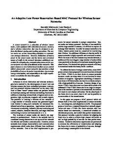
Fig. 3 shows the σ min for all four inputs at Qe = 0.4 pu. According to Fig. 3, it can be seen that the EM mode controllability with δ E is more than other inputs and is the least affected by loading conditions.
From Eqs. (19) to (23) in comparison with Eq. (24) the K-constant values can be calculated as shown below:
0.08
K10 = (-2xq L)(xq E + xqt )Vb cosδ/(xq ∑ ) +
0.06
(xqt - xqE )cosδ BmB /2xq ∑ ) + (2x′d L - Eq′ )((xdE - xBd )sinδ E mE /2xd ∑ + (xdE - xdt )sinδ BmB /2xd ∑ ) K 13 = 2xq LxBq - xqE )cosδ E Vdc /2xq ∑ + (2xd′ S - E ′q)((xdE - xBd )sinδ E Vdc /2xd ∑ )
K14 = 2xq L(xBq + xqE )sinδ EVdc mE /2xq ∑ + (2x′d S - E q′ )((xdE - xBd )cosδ E mEVdc /2xd ∑ )
K15 = 2xq L(xqt - xqE )cosδ BVdc /2xq ∑ + (2xd′ S - E q′ )((xdE - xdt )sinδ BVdc /2xd ∑ ) K16 = 2Xq L(xqE - xqt )sinδ BVdc mB /2xq ∑ + (2x′d S - Eq′ )((xdE - xdt )cosδ BVdc mB /2xd ∑ )
(25) (26)
Vb sin δ ) - (m E cos δ E VdcxqE )/(2x q ∑ ) + (x qt /x q ∑ )(0.5m B cos δ BVdc + Vb sin δ )
Delta E mB mE Delta B
0.04
0.02
(27)
0 0
0.5
Time(s)
1
1.5
(28)
Fig. 3. Minimum singular value with all inputs at Qe = 0.4 pu.
(29)
3. Design of Damping Controllers
(30) (31)
L = (m E cos δ E Vdc x Bq )/(2x q ∑ ) (x qE /x q ∑ )(0.5m B icos δ BVdc +
Delta W
E q′Vb sinδ ((xdE - xdt )/xd ∑ )(2xd′ S + 1)
K11 = ((xBB - xE )/xd ∑ )(2xd′ S - Eq′ ) - S K12 = 2Xq L((xBq - xqE )cosδ E mE /2xq ∑ +
(34)
(32)
3.1 Lead-Lag Controller The damping controllers are designed to produce an electrical torque in phase with the speed deviation. The four control parameters of the UPFC (i.e., mE, mB, δ E and δ B ) can be modulated in order to produce the damping torque. The speed deviation Δω is considered as the input to the damping controllers. The structure of the UPFC based damping controller is shown in Fig. 4. It consists of gain, signal washout and phase compensator blocks. The parameters of the damping controller are obtained using the phase compensation technique [12]. According to Fig. 4, the structures of Lead-Lag controllers with Δω and
M. R. BANAEI and A. HASHEMI
ΔPe inputs are very similar. The detailed step-by-step pro-
cedure for computing the parameters of the damping controllers using the phase compensation technique is given below. At first, the natural frequency of oscillations ωn is calculated for the mechanical loop.
ΔPe
K dc
Gain Δω
K dc
Gain ΔQe
ΔPe
Δu
1 + sT1 1 + sT2
Gc ( s ) =
Assuming one Lead-Lag network, T1 = aT2 the transfer function of the phase compensator becomes, GC ( s ) =
sTw 1 + sTw
Gc ( s ) =
Signal Washout
Gc′ ( s ) =
1 + sin γ 1 − sin γ 1 T2 = ωn a
Phase Compensator
1 + sT1′ 1 + sT2′
H( s )
(38)
The require gain setting Kdc for desired value of damping ratio ξ = 0.5 is obtained as,
Δω
K dc =
1 + sT1 1 + sT2
2ξω n M
(39)
GC ( s ) γ ( s )
And GC ( s ) and γ ( s ) are computed at s Δu ( δ E )
1 + sT3 1 + sT4
Fig. 4. Structure of UPFC based damping controller. ωn =
(37)
a=
Δu
1 + sT1 1 + sT2
1 + saT2 1 + sT2
Since the phase angle compensated by the Lead-Lag network is equal to − γ , the parameters a and T2 are computed as,
Phase Compensator
∑
ΔQ e
201
K 1ω 0 M
(35)
That the amounts of ω0 , K 1 and M has been presented in Appendix A. For computing the phase lag between Δu and ΔPe at s = jωn , we should calculate the transfer function of Fig. 5, which is a simple control model of Fig.6. The phase Lead-Lag compensator GC is designed to provide the required degree of phase compensation for 100% phase compensation. ∠GC ( jω) + ∠γ ( jω) = 0
= jω n .
The signal washout is the high pass filter that prevents steady changes in the speed from modifying the UPFC input parameter. The value of the washout time constant TW should be high enough to allow signals associated with oscillations in rotor speed to pass unchanged. From the view point of the washout function, the value of TW is not critical and may be in the time range of 1s to 20s. TW equal in 10s is chosen in the present studies. Fig. 6 shows the transfer function of the system relating the electrical component of the power Δ PEM produced by the damping controller δ E . ΔPEM + +
Δω
∑
UPFC Damping Controller
+
K2
K6
Δu _
K pd
1 K 3 + Tdo′
K pu
(36)
_
K qu
∑
+
_
K qd
K a 1 + sT
_ a
K vu
∑
+ _
Δ V ref
K vd
K8 +
∑ +
1 s + K
9
K cb
Fig. 5. The graph between ∆PEM and ∆u.
Fig. 6. Transfer function of the system relating component of electrical power ΔPEM produced by damping controller δ E .
An Adaptive UPFC based Stabilizer for Damping of Low Frequency Oscillation
202
In order to design a controller with ΔQe input signal for
K = R −1 ( B T s + N T ) [ K , s, e] = LQR ( A, B, Q, R, N )
damping signal δ E , transfer function H ( s ) = ΔQe must be
(45)
Δω
3.3 Adaptive Controller
calculated according to Eq. (24) as shown below:
H( s ) =
ΔQe K10 H 12 + K11 H 32 + K12 H 52 + K14 = H 22 Δω
(40)
So it can be obtained: ∠ΔQe = ∠H( s ) + ∠Δω
(41)
Therefore, the Lead-Lag compensator Gc′ ( s ) must be designed to compensate for the phase shifting between ΔQe and Δω . The transfer function between ΔQe
and Δω according to Eq. (24), has been calculated as follows:
H( s ) =
ΔQe K10 H 12 + K11 H 32 + K12 H 52 + K14 = H 22 Δω
(42)
In order to design the damping controller with input ΔPe + ΔQe , two Lead-Lag compensators must compensate for the phase angle between Δu and ΔPEM together.
3.2 LQR Controller The LQR controller for a system described with the • state-feedback equation x = Ax + B can calculate the optimal amount of K so that the state feedback u = − Kx according to Fig. 7 to minimize the integral of Eq. (43).
Fig. 8 shows a block diagram of a process with a selftuning regulator (STR). The parameters of the power system transfer function are estimated by estimation block with samples taken from input Δδ E and output Δω with a specified sampling time [15], [16]. It has been shown as the discrete transfer function of the state equation of the power system (7) as follows: H (q ) =
b 0q 4 + b1q 3 + b 2 q 2 + b 3q + b 4 Δω(q ) B(q ) = = Δδ E A (q ) q 5 + a 1q 4 + a 2q 3 + a 3q 2 + a 4 q + a 5
The block labeled controller design contains the computation’s Diophantine equation required to perform a design of a controller with a specified method and few design parameters that can be chosen externally. The recursive leastsquare method (RLS) will be used for parameter estimation and the design method is a deterministic pole placement (MDPP). A general linear controller can be described by Ru( t ) = Tu c ( t ) − Sy( t )
+
PLANT
+
x
c
Self − Tuning − Re gulator
Specificaton
Power System Parameters
Controller
y
Estimation
Controller Parameters
-
Re ference Controller
Fig. 7. Block diagram of a state-space based system with negative feedback. ∞
0
(43)
In addition to calculating the optimal value of K, the LQR calculates the solution S of the associated Riccati equation according to equation (44). −1
A s + sA − (sB + N ) R (B s + N ) + Q = 0 T
T
T
Output
Fig. 8. Block diagram of Self Tuning Regulator. T R
uC
u
y
B A
∑
S R v
Controller
uc
Ru = Tu c − Sy
(44)
The eigenvalues of closed-loop system e = eig ( A − B * K ) is calculated, too. Note that the value of K is calculated using the response of the Riccati equation according to equation (45).
Power System
Input
K
J(u ) = ∫ ( x T Qx + u T Ru + 2x T Nu)dt
(47)
Where R, S and T are polynomials. A block diagram of the closed-loop system is shown in Fig. 9.
Design u
(46)
uC
u
∑
BT AR + BS
Plant
y
B A
y
Fig. 9. A general linear controller with 2 degrees of freedom.
M. R. BANAEI and A. HASHEMI
203
General equations of R, S and T are polynomials and have been calculated by MDPP as follows:
(48)
T ( q ) = t0 q + t1q + t2 q + t3 q + t4 4
3
2
The closed-loop characteristic polynomial is thus:
AR + BS = AC
(49)
2. The Diophantine equation is formed as below and will be solved for finding R ′ and S polynomials: (55) AR ′ + B − S = Ao Am 3. Calculating R and T control as below: R = R ′B +
The key idea of the design method is to specify the desired closed-loop characteristic polynomial AC . The polynomial R and S can then be solved from Eq. (49). In the design procedure we consider polynomial AC to be a design parameter that is chosen to give desired properties to the closed-loop system. Eq. (49), which plays a fundamental role in algebra, is called the Diophantine equation. The equation always has solutions if polynomials A and B do not have common factors. The solution may be poorly conditioned if the polynomials have factors that are closed. The solution can be obtained by introducing polynomials with unknown coefficients and solving the linear equations obtained. In fact, in an off-line state, the adaptive controller parameters are as according to Fig.10. A B Am Bm Ao
Dynamic Pole Assynment
(54)
That B + and B − are strongly and poorly damped roots polynomials.
R( q ) = q 4 + r1q 3 + r2 q 2 + r3q + r4
S ( q ) = s0 q 4 + s1q 3 + s2 q 2 + s3 q + s4
Bm = B + B −
R S T
Fig. 10. Block diagram of off-line adaptive controller inputs and outputs.
(56)
T = Ao Bm′
(57)
But the on-line control design consists of the three following steps: 1. Selection polynomials of Am , Bm and Ao . ^ 2. Calculation of θ matrix with RLS as in the equation below: y( q ) =
B u( q ) A
(58)
A( q ) y( q ) = B( q )u( q )
(59)
y( q ) + a 1 y( q − 1 ) + a 2 y( q − 2 ) + .... + a n y( q − n ) = b1 u ( q + m − n − 1 ) + .... + b m u ( q − m ) ⎡ a1 ⎤ ⎢ .⎥ ⎢ ⎥ ⎢ .⎥ ⎢ .⎥ ⎢a ⎥ y( q ) = [− y( q − 1 ) ...... − y( q − n ) u( q + m − n − 1 ) ..... u( q − m )] ⎢ n ⎥ ⎢ b1 ⎥ ⎢ .⎥ ⎢ ⎥ ⎢ .⎥ ⎢ .⎥ ⎢ ⎥ ⎣bm ⎦
y( q ) = φ T ( q − 1 )θ
[
Bm is the desired transfer function of power system. Bm Am and Am polynomials must be chosen in the way that the adaptive controller can omit the perturbation in input mechanical torque with suitable speed. The desired transfer function used in this paper according to Eq. (46) offers as below:
[
]
P( q ) = P( q − 1 ) − P( q − 1 )φ ( q ) I + φ T ( q )P( q − 1 )φ ( q )
φ ( q )P( q − 1 ) = [I − K ( q )φ ( q )]P( q − 1 ) T
T
θ ( q ) = θ ( q − 1 ) + K ( q ) ⎡⎢ y ( q ) − φ T ( q ) θ ( q − 1 )⎤⎥ ^
^
^
⎣
⎦
−1
(61)
]
K ( q ) = P( q )φ ( q ) = P( q − 1 )φ ( q ) I + φ T ( q )P( q − 1 )φ ( q )
×
(60)
−1
(62) (63) (64) (65)
3. Calculation of R , S and T polynomials with MDPP.
3.4 Simulation Results
4
y (q ) B m (q ) q = = u (q) A m (q) q 5 + a1q 4 + a 2q 3 + a 3q 2 + a 4q + a 5
(50)
According to Fig.10, designing an adaptive off-line controller (MDPP technique) consists of the three following steps: 1. Selection polynomials of Am , Bm and Ao as below: deg Am = deg A = n
(51)
deg Bm = deg B = m
(52)
deg Ao = deg A − deg B + − 1
(53)
Eigen-value (electro mechanical mode) calculations should be done before any controller designing. Table 1 shows the electro mechanical mode of the system without any controller, equipped with Lead-Lag, LQR and an adaptive controller. Based on the above table, pole placement of the closed loop system equipped with controllers has improved in comparison with open loop systems and an on-line adaptive controller has the best result among them. The linearized model of the case study system in Fig. 1 with parameters shown in Appendix. A and K parameters shown in Appendix. C, has been simulated with MATLAB/
An Adaptive UPFC based Stabilizer for Damping of Low Frequency Oscillation
204
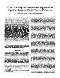
SIMULINK. In order to examine the robustness of the damping controllers to a step load perturbation, it has been applied a step duration in mechanical power (i.e., ΔPm = 0.01 pu ) to the system seen in Fig. 2. Consequently, the reference system has four inputs; the damping input signal in Fig. 3 has been added to the most effective input δ E calculated by the SVD technique. Fig. 11 shows the dynamic responses of Δω with different operating conditions by Lead-Lag controller for δ E input control signal. Table 1. Electromechanical mode of the individual terms at Nominal loading condition Without controller
0.1052 ± j 2.8455
Lead-Lag
δE
mE
− 1.780 ± j 2.7446
− 0.46 ± j 2.9
δB
mB
− 1.4187 ± j7276 3.3661 ± j1.3204
LQR
− 0.417 ± j 2.9290
On-line Adaptive controller
− 1.394 ± j0.3304
It is clearly seen that the dynamic performance at a heavy condition is better significantly compared to that obtained at light and nominal loadings because the speed deviation has been damped with minimum settling time at a heavy condition. The response of the nominal condition has the second rank after the heavy condition because its settling time is less than five seconds and its peak amplitude value is even greater than the heavy condition. According to the above, it can be calculated by dynamic responses to the ΔPm = 0.01 pu perturbation for other input control signals that by comprising all of the responses, we can see that adding the damping control signal to δ E is better than other control inputs because of its speed oscillation damp with a shorter time than five seconds and minimum amplitude. Fig. 12 shows the dynamic responses of Δω for nominal operating conditions by Lead-Lag controller with ΔQe , ΔPe and ΔPe +ΔQe input control signal. By comparing the above figures with those obtained by the controller with Δω input in Fig. 11.b, it can be seen that the response quality of Δ Qe , ΔPe , ΔPe + ΔQe based 2
x 10
-5
Delata W
8
Delta W
6 4
-2
2
-4 0
0 0
5
10
Time(s)
15
x 10
5
10 Time(s)
15
20
(a)
15 -4
(a)
10
-5
x 10
5 Delta W
10 Delta W
0
5
0
0 -5 0
1
2
Time(s)
3
4
-5 0
5
(b) -5
x 10
4
x 10
5
10
Time(s)
15
20
25
(b)
-4
Delta W
Delta W
10 5 0 -5 0
1
2
3 Time(s)
4
5
6
2
0
-2 0
1
2 Time(s)
3
4
(c)
(c)
Fig. 11. Dynamic responses of Δω with input control signal δ E for different operating conditions (a): Light load (b): Nominal load (c): Heavy load.
Fig. 12. Dynamic responses of Δω at nominal operating conditions for different input control signal (a): ΔQe (b) : ΔPe (c) : ΔPe + ΔQe .
M. R. BANAEI and A. HASHEMI
controller is less than Δω based controller in terms of peak amplitude. Therefore it has been used from Δω input signal for LQR and adaptive controller designing. It can be seen by the dynamic responses to the ΔPm = 0.01 pu perturbation of input mechanical power for systems equipped with an LQR controller in the following. Fig. 13 shows the dynamic responses of Δω at nominal condition with LQR damping controller. Dynamic response has nearly the same quality in comparison with the Lead-Lag controller at Fig. 11 (b) in terms of settling time and peak amplitude. Fig. 14 is related to an estimation of the control reference system in the on-line adaptive controller at nominal condition calculated by RLS technique. Some of the coefficients of the transfer function -5
15
x 10
5 0 -5 0
1
2
Time(s)
3
4
5
Fig. 13. The dynamic responses of Δω at nominal condition with LQR damping controller.
Coefficient Amount
150
Estimated b4 b4
100
of the power system in Eq. (45) and their estimation by RLS technique have been shown in Fig. 14. It can be seen that the estimation of transfer function coefficients have been converged to the polynomials of the reference power system model at less than 20 iterations. After estimation of the transfer function of the reference control model, in order to calculate the on-line adaptive controller polynomial coefficients, the Diophantine equation must be solved. In the following, it has been shown some of the parameters R and S in Fig. 15 at a nominal condition. It can be considered that the coefficients have been converged at less than 20 iterations. Samples have been taken from the input and output of the transfer function of the case study with sampling time Ts = 0.01s for adaptive control designing. The desired transfer function of Eq. (50) has been presented in Appendix B. Fig. 16 shows the dynamic responses of Δω with adaptive controller at nominal operating loads due to ΔPm = 0.01 pu perturbation. It is clearly seen that the dynamic performance at different loading conditions have an almost similar quality in terms of settling time and peak amplitude. From comparisons between the results of the adaptive controller with Lead-Lag, LQR controllers and without controller, it can be seen that the dynamic response of the system equipped with an adaptive controller (Fig. 16) in comparison with the system equipped with an LQR controller (Fig. 13) has greater quality because the adaptive controller could decrease the settling time for more than 0.1 seconds. Also, the dynamic response of the system equipped with the adaptive controller (Fig. 16) in comparison with a system equipped with Lead-Lag controller (Fig. 11 (b)) has less settling time and the peek amplitude amount of the adaptive control is 15
50
Amount of Polynomial Cofficient
Delta W
10
0
0
20
40 60 Number of Samples
80
100
(a) Estimated a1 a1
2
5
-4 -6 80
20
40 60 Number of Samples
80
0.5
-2
40 60 Number of Samples
10
100
(a)
0
20
r 2
0 0
Amount of Polynomial Coefficient
Coefficient Amount
4
-8 0
205
100
S0
0.4 0.3 0.2 0.1 0 -0.1 -0.2 0
20
40 60 Number of Samples
80
100
(b)
(b)
Fig. 14. Adaptive controller polynomial coefficients of RLS estimated plant at nominal operating condition:(a) : b4 (b) : a1 .
Fig. 15. Adaptive controller parameters calculated with Diophantine equation at nominal operating condition:(a): r2 (b) : s0 .
An Adaptive UPFC based Stabilizer for Damping of Low Frequency Oscillation
206
2
x 10
-5
Acknowledgements
1.5
This work was supported by the Azarbaijan University of Tarbiat Moallem.
1
Δω
0.5 0
Appendix
-0.5 -1 -1.5 -2 0
0.1
0.2
0.3
0.4
0.5
Time(s)
M = 2 H = 8.0 MJ / MVA
(a)
D = 0.0 Tdo′ = 5.044 s
-5
x 10 2
X d = 1.0 pu
Δω
1
X q = 0.6 pu 0
X d′ = 0.3 pu Excitation System: K a = 100
-1
-2 0
0.1
0.2
0.3
0.4
0.5
Time(s)
(b) -5
x 10 2 1
Δω
A: The test system parameters are: Generator:
0
X BV = 0.3 pu
-1 -2 0
Ta = 0.01s Transformer : X tE = 0.1 pu X E = X B = 0.1 pu X E = X B = 0.1 pu Transmission Line:
0.1
0.2
0.3
0.4
0.5
Time(s)
(c)
Fig. 16. Dynamic responses of Δω with adaptive controller at different operating conditions due to ΔPm = 0.01 pu (a): Light (b): Nominal (c): Heavy.
less than Lead-Lag controller, too. Moreover, the proposed adaptive controller stabilizes the power system, while the power system without a controller is unstable according to Table 1. So, the adaptive controller gives the best results according to Table 1.
4. Conclusion In this paper, a UPFC has been used for dynamic stability improvement and state-space equations have been applied for the design of damping controllers. Simulation results operated by MATLAB/SIMULINK show that using input speed deviation signal is better than inputs of power deviations, and also adding control signals to the active power control loop of the shunt inverter decreases speed oscillations effectively. According to the simulation results, the designed adaptive controller for the system has the perfect effect in oscillation damping and dynamic stability improvement in comparison with other controllers.
X e = X BV + X B + X tE = 0.5 pu Operating Condition: Vt = 1.0 pu Pe = 0.8 pu Vb = 1.0 pu
f = 60 Hz Parameters of DC Link: Vdc = 2 pu C dc = 1 pu
B: Adaptive controller parameters: Am = ( q − 0.01 )( q − 0.03 )( q − 0.02 )( q − 0.1 )( q + 0.1 ) Bm = q 4
AO = 1
deg Bm = deg B = m = 4 deg Am = deg A = n = 5 C: K parameters K1 =
(Vtd − I tq xd′ )( xdE − x dt )Vb sin δ
K2 =
xd ∑
− ( x BB + x E )Vtd + xd ∑ xd
+
( x q I td + Vtq )( xqt − x qE )Vb cos δ xq ∑
( x BB + x E ) x ′d I tq xd ∑
( x ′ − x d )( x BB + x E ) K3 = 1+ d xd ∑ ( x d′ − x d )( x dE − x dt )Vb sin δ xd ∑ Vtd x q ( xqt − x qE )Vb cos δ Vtq x ′d ( xdtE − x dt )Vb sin δ − K5 = Vt x q ∑ Vt xd ∑
K4 = −
M. R. BANAEI and A. HASHEMI
K6 =
Vtq ( x d ∑ + x d′ ( x BB + x E ))
Vt x d ∑ K 7 = 0.25C dc ( Vb sin δ ( m E cos δ E x dE − m B cos δ B x dt )) − m B cos δ B x dt +
xd ∑
Vtd x q ( x qE − x Bq ) m EVdc sin δ E
K vδE =
2Vt x q ∑
K vb =
K 9 = 0.25Cdc(
2xd ∑
K vd =
2xq ∑
2Vt x d ∑
K cδe =
)
( Vtd − I tq x d′ )( x Bd − x dE )Vdc sin δ E 2 xd ∑
( Vtd − I tq x′d )( xBd − xdE )Vdc mE cosδ E 2 xd ∑
+
−
m B ( x dt − x qE ) sin δ E 2 xd ∑
(m B sin δ B x qE + m E sin δ E x Bq )
( Vtd − I tq xd′ )( xdt − xdE ) xdc sin δ B
2 xq ∑
K cb = 0.25C dc
)
Vdc sin δ B (−m E cos δ E x dE + m B cos δ B x dt ) + 2 xd ∑
Vdc cos δ B (m B sin δ E x qt − m E sin δ E x qE )
2 xq ∑
2 xq ∑ +
K cδB
( xq I td + Vtq )( xqt − xqE )Vdc cos δ B
( Vtd − Itq xd′ )( xdE + xdt )VdcmB cosδ B
0.25m B = (cos δ B I Bq − sin δ B I Bd ) + C dc
( m cos δ E x dE + m B cos δ B x dt ) 0.25 ( m BVdc cos δ B E + 2 xd ∑ C dc
2 xq ∑
2 xd ∑
2 xq ∑
0.25m E (cos δ E I Eq − sin δ E I Ed ) + C dc
m EVdc sin δ E
( xq I td + Vtq )( − xBq + xqE )Vdc mE sinδ E
K pδB =
+
(m E cos δ E x Bd − m B cos δ B x dE ) 0.25 + (m EVdc cos δ E 2 xd ∑ C dc
+
2 xq ∑
2 xd ∑
+
2Vt x d ∑
( x qt − x qE )m B cos δ B
2 xq ∑
( x q I td + Vtq )( x Bq − x qE )Vdc cos δ E
K pb =
2Vt x q ∑
2Vt x d ∑
Vtq m B x d′ ( x dE + x dt )V dc cos δ E
Vdc cos δ E (m E sin δ E x Bq − m B sin δ B x qE )
+
2xq ∑
K pδE =
+
Vtd x q ( x Bq − x qE )m E cos δ E
Vtq m E x d′ ( x Bd − x dE ) sin δ E
2Vt x q ∑
Vtq x d′ ( x dt − x dE )Vdc sin δ E
V sin δ E (m E cos δ E x Bd − m B cos δ B x dE ) + K ce = 0.25C dc dc 2 xd ∑
mE cos δ E (−mB sin δ B x qE + mE sin δ E x Bq )
K pe =
2Vt x q ∑
+
mE sin δ E (mE cos δ E x Bd − mB cos δ B x dt ) 2xd ∑ mB cos δ B (mB sin δ B x qt − mE sin δ E x qE )
Vtd x q ( x qE − x qt ) m BVdc sin δ E
Vtq x d′ ( x Bd − x dE ) m EVdc cos δ E
−
2Vt xq ∑
K vδB =
m B cos δ B x E + m E cos δ E x BB xd ∑ mB sin δ B (mB cos δ B x dt − mE cos δ E x dE )
−
Vtd x q ( x qt − x qE )Vdc cos δ E
Vb cos δ ( m B sin δ B x qt − m E sin δ E x qe
K 8 = −0.25
207
+
m BVdc sin δ B
( xq Itd + Vtq )( −xqt + xqE )VdcmB sinδ B
( − m B sin δ E x qt + m E sin δ E x qE ) 2 xq ∑
)
2 xq ∑ K pd = ( Vtd − I tq xd′ )(
( xdt − xdE )mB sin δ B + 2 xd ∑
( x Bd − xdE )mE sin δ E )+ 2 xd ∑ ( xq I td + Vtq )(
( xqt − xqE )mB cos δ B 2 xq ∑
References [1]
+
( x Bq − xqE )mE cos δ E
[2]
2 xq ∑
( x d′ − x d )( x Bd − x dE )Vdc sin δ E 2 xd ∑ ( x d′ − x d )( x Bd − x dE )m EVdc cos δ E =− 2 xd ∑ ′ ( xd − xd )( xdt − xdE )Vdc sin δ B
K qe = − K qδe
K qb = −
2 xd ∑
( x′ − xd )( xdE − xdt )mBVdc cos δ B K qδB = − d 2 x∑ ( xBd − xdE )mE sin δ E ( xdt − xdE )mB sin δ B K qe = −( x′d − xd )( ) + 2 xd ∑ 2 xd ∑ Vtd ( x Bq − x qE )Vdc cos δ E Vtq ( x Bd − x dE )Vdc sin δ E K ve = − 2Vt x q ∑ 2Vt x d ∑
[3] [4]
[5]
H. F. Wang, “Damping Function of Unified Power Flow Controller,” IEEE Trans. Proc-Gener Transm. Distrib, Vol. 146, No. 1, pp. 81-87, January 1999. Chuan Qin, WenJuan Du, H.F Wang, Qun Xu and Ping Ju, “Controllable Parameter Region and Variable-Parameter Design of Decoupling Unified Power Flow Controller,” Transmission and Distribution Conference and Exhibition: Asia and Pacific, IEEE/PES, Dalian, China, 2005. H .F. Wang, “Damping function of unified power flow controller,” IEE Proc.Gen.Trans. and Distrib., Vol. 146, No. 1, 1999, pp. 81-87. M. A. Abido, Ali T. Al-Awami, Y. L and Abdel-Magid, “Simultaneous Design of Damping Controllers and Internal Controllers of a Unified Power Flow Controller,” Power Engineering Society General Meeting, Montreal, IEEE, 2006. C. M. Yam and M. H. Haque, “A SVD based controller of UPFC for power flow control,” The 15th Power System Computation Conference, Session 12, Paper 2,
208
[6]
[7] [8]
[9]
[10]
[11] [12] [13] [14]
[15]
An Adaptive UPFC based Stabilizer for Damping of Low Frequency Oscillation
pp. 1-7, Aug. 2005. M. A. Abido, “Particle Swarm Optimization for multimachine Power System stabilizer design,” Power Eng, Society Summer Meeting, IEEE, Vol. 3, 15-19, pp.1346-1351, July 2001. H. F. Wang, “Application of modeling UPFC into multi-machine power systems,” IEE Proc. Gen. Trans and Disturb, Vol. 146, No. 3, pp.306-312, 1999. A. Nabavi-Niaki and M. R. Iravani, “Steady-state and dynamic models of unified power flow controller (UPFC) for power system stydies,” IEEE Trans. Power System, Vol. 11, No.4, pp.1937-1943, Nov. 1996. Radha P. Kalyani and Ganesh K.Venayagamoorthy, “Two Separately Continually Online Trained Neurocontrollers for a Unified Power Flow Controller,” Proceedings of International Conference on Intelligent sensing and Information processing, (IEEE Cat. No. 04EX783), pp.243-248, 2004. A. J. F. Keri, X. Lombard, A. A. Edris, “Unified Power Flow Controller: Modeling and Analysis,” IEEE Trans Power Delivery, IEEE Transactions on Vol. 14, No. 2, pp. 648-654, April 1999. H. F. Wang, “Application of modeling UPFC into multi-machine power system,” IEE Proc. Gen. Trans and Distrib., Vol. 146, No. 3, pp. 306-312, 1999. L. Rouco, “Coordinated design of multiple controllers for damping power system oscillation,” Elec Power Energy Systems, 21, 517-530. B. C. Pal, “Robust damping of interarea oscillations with unified power flow controller,” IEE Proc. Gen. Trans. and Distrib., Vol. 149, No. 6, pp.733-738, 2002. D. Nazarpour, S. H. Hosseini and G. B. Gharehpetian, “An adaptive STATCOM based stabilizer for damping generator oscillations,” pp. 60-64, 7-11 December 2005, Bursa/Turkey, ELECO 2005. Chin-Hsing cheng and Yuan-Yih Hsu “Damping of generator oscillations using an adaptive static VAR compensator,” IEEE Transaction on power systems Vol. 7, No. 2, May 1992.
Mohamad Reza Banaei was born in Tabriz, Iran, in 1972. He received his M.Sc. degree from the Poly Technique University of Tehran, Iran, in control engineering in 1999 and his Ph.D. degree from the electrical engineering faculty of Tabriz University in power engineering in 2005. He is an Assistant Professor in the Electrical Engineering Department of Azarbaijan University of Tarbiat Moallem, Iran, which he joined in 2005. His main research interests include the modeling and controlling of FACTS devices, power systems dynamics, power electronics and renewable energy.
Ahmad Hashemi was born in Kermanshah, Iran, in 1984. He received his B.S. degree in power electrical engineering from K. N. Toosi University of technology, Tehran, Iran, in 2006 and his M.S. degree from Tarbiat Moallem University of Azarbaijan, Tabriz, Iran, in 2009. His main research interests are FACTS devices modeling, adaptive control and Neural Network optimizations.