AN ALL-OPTICAL CODE CONVERTER SCHEME FOR OCDM ROUTING NETWORKS Yonggang Wen, Lian Kuan Chen, Keang-Po Ho, Frank Tong Lightwave Communications Lab., Department of Information Engineering, The Chinese University of Hong Kong, Shatin, N. T., Hong Kong; Phone: +852-2609 8479; Fax: +852-2603 5032; Email:
[email protected] Abstract: A novel all-optical code converter scheme using a TOAD-based architecture is proposed for OCDM routing networks. Theoretical analysis of BER and power penalty is given and shows less than 0.22 dB extinctionratio-induced power penalty. Introduction Recently, much attention has been paid to the research of combining optical code division multiplexing (OCDM) with WDM in photonics routing networks /1-3,8/. While less attractive in long haul transmission, OCDM can perform better for switching or routing in local-area network (LAN) environment. In OCDM routing networks, the concept of a virtual optical code path (VOCP) was introduced for the end-to-end connection within the transport layer of the network /1/. As each VOCP connection consists of several concatenated spans, denoted as virtual optical code channels (VOCC) here, ways to allocate the finite Optical Orthogonal Codes (OOC) and route the data along a particular VOCP have to be investigated. Analogous to the role of wavelength conversion, one of the solutions is code conversion. So far, two types of code converters have been suggested, the first scheme /1/ uses OE-EO method for coherent OCDM networks, the other /3/ includes the look-up table and also requires OE-EO processing. Both methods suffer from the bandwidth bottleneck of OE-EO. Thus all optical processing for code-conversion is necessary for future high-speed networks. In this paper, we report the scheme of an all-optical code converter based on an all-optical logic XOR gate for OCDM routing networks. The power penalty due to the code conversion is analysed. Scheme and basic principle Figure 1 shows the schematic diagram of our proposed alloptical code converter. To have a large system capacity, the sequence inversion keyed (SIK) direct spread (DS) code division multiple-access (CDMA) scheme is considered /7/. In an optical SIK system, the data bits are modulated either by a unipolar signature sequence Ci or its complement Ci , depending on whether the transmitting bit is ZERO or ONE, respectively. It was shown that an optical SIK DSCDMA LAN using unipolar-bipolar transceiver pair has the same capacity performance as that of a bipolar-bipolar system /7/. In our proposed routing scheme, the main code-conversion function is implemented by an all-optical XOR gate. In the routing node, the input signal is a SIK DS-CDMA signal modulated by the code Ci, corresponding to the VOCC of VOCC(i). An optical code converter is used to convert the code Ci to code Cj, corresponding to the routing from VOCC(i) to VOCC(j). Here the concept of conversion code Qij is introduced. By processing the input signal with Qij, the information carried in the VOCC(i) can be coupled to
the VOCC(j). Thus our proposed code converter realizes the all-optical CDMA switching function. For our scheme, the conversion code Qij must have two properties of Ci ⊕ Qij = C j and Ci ⊕ Qij = C j . We found that with Qij = Ci ⊕ C j , we can obtain Ci ⊕ Qij = Ci ⊕ (Ci ⊕ C j ) = Ci ⊕ Ci ⊕ C j = 0 ⊕ C j = C j
Ci ⊕ Qij = Ci ⊕ (Ci ⊕ C j ) = Ci ⊕ Ci ⊕ C j = 1 ⊕ C j = C j Thus the unique conversion code Qij = Ci ⊕ C j
can
facilitate the routing function from VOCC(i) to VOCC(j). For example, for the 4-chip Walsh codes having C1=[1 0 1 0] and C2=[1 1 0 0], the code conversion function from C1 to C2 is verified by
Q12 = C1 ⊕ C2 = [0 1 1 0] C1 ⊕ Q12 = [1 0 1 0] ⊕ [0 1 1 0] = [1 1 0 0] = C2 C1 ⊕ Q12 = [0 1 0 1] ⊕ [0 1 1 0] = [0 0 1 1] = C2
Code Converter Architecture The core element of our code converter is an all-optical XOR logic gate. In SIK DS-CDMA system, very fast processing rate is essential. Among various XOR implementations, the TOAD-based /4/ all-optical XOR logic gate /5,6/ is chosen for its fast processing speed. A proposed code converter is shown in Fig. 2. The code converter is a modified TOAD that has two arms of control pulse input. One is the routing node’s input channel code Ci, and the other is the conversion code Qij. These two signals are of the same wavelength, whereas the XOR clock is on a different wavelength, such that they can be separated by an optical filter at the output port. After the clock enters the loop through the main coupler, it splits into two pulses, a clockwise (CW) and a counter-clockwise (CCW) pulse. Each of these two pulses passes through the SOA once, and returns to the main coupler at the same time. When the two control arms have the same signal level, 1 or 0, the CW and CCW pulses will experience the same transmission properties of the SOA. The clock train is then totally reflected into the input port and no pulse appears in the output port. On the other hand, if one of the two control arms has a 1 level and the other has a 0 level, the CW and CCW pulses will experience different transmission properties of the SOA. The clock pulse train will come out from the output port of the TOAD when the phase difference between the CW and CCW pulses is π. Thus, the output channel code C j = Ci ⊕ Qij is obtained at the output port of the code converter.
Analysis and Discussion
/5/
For the SIK DS-CDMA optical network, the BER bound was derived with an optical unipolar-bipolar transceiver pair /8/,
/6/ /7/
2 ( K − 1) 2 ( RPt ) + 4eKBPt + 16BNth 3N
(1) /8/
and Pe = Q
(
SNR
)
(2)
where R is the PIN diode responsivity, Pt is the received chip power, K is the number of simultaneous users, N is the code length, B is the data rate, Nth is the thermal noise and Q(*) is the Q-function. For the conventional SIK DS-CDMA optical network without a code converter, power penalty mainly results from the extinction ratio of the OCDM encoder. If the extinction ratio of OCDM encoder is rex0 = P0/P1, the chip power after a balance decoder /7/ is decreased to (1-rex0)Pt. So the power penalty for the network without code conversion is 1 (3) δ ( rex 0 ) = 10log10 1 − rex 0 When code converter is employed, power penalty arises from the code converter’s nonzero extinction ratio, which is originated from the encoder’s nonideal extinction ratio. After some derivation, the extinction ratio of the code converter is rex1 = [1-cos(rex0π)]/2. Therefore power penalty for the network with code conversion is 2 (4) δ ( rex 0 ) = 10log10 1 cos + r π ( ) ex 0 Figure 3 shows the power penalty of networks without and with code conversion as a function of rex0. Due to the regeneration effect, the network with conversion suffers less power penalty than the network without conversion when rex0 is below 0.5. Using a reported experimental data for an optical XOR gate demonstration with an on/off ratio of 13 dB /6/, the extinction ratio, rex1, of the code-converter is lower than 0.05. Thus from Equation (4), the proposed code converter can work well in OCDM routing network by inducing less than 0.22 dB power penalty. Conclusion A novel ultrafast all-optical code converter for OCDM routing networks is proposed. By introducing a unique conversion code Qij, all-optical code-division routing can be implemented by XOR processing in the optical layer. The proposed code converter eliminates the OE/EO bottleneck that limits the speed of OCDM routing. Theoretically, with a reported extinction ratio rex1 of 13 dB, extinction-ratio-induced power penalty is reduced from 0.675-dB to 0.22-dB. References /1/ /2/ /3/ /4/
K. Kitayama, IEEE JSAC, Vol. 17, 1998, pp.13091319 K. Kitayama, ECOC’98. Vol. 1, 1998, pp.339-340 C. Eyoh, et al., ICICS’97, 1997, pp.873-877. J. P. Sokoloff, et al., IEEE Photonics Technology Letters, Vol. 5, July 1993, pp.787-790.
Channel i Ci
Optical XOR
Channel j Cj
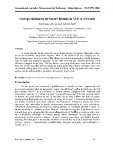
Qij Conversion Controller Figure 1. The basic schematic diagram of the novel alloptical code converter.
Ci
MLPG Encoder
EDFA SOA
RF Source Qij MLPG
OBPF
Cj
Clock
Figure 2. The proposed code converter architecture. MLPG: Mode-locked Pulse Generator. OBPF: optical bandpass filter. SOA: Semiconductor optical amplifier. Power Penalty (dB)
( RPt )
2
SNR =
A. J. Poustie, et al. Optics Communications, 159(1999), pp.208-214. T. Houbavlis, et al, IEEE Photonics Technology Letters, Vol. 11, March 1999, pp.334-336. F. Khaleghi, and M. Kavehrad, IEEE Tran. Comm., Vol. 44, October 1996, pp.135-1339. K. Kitayama, ECOC’99. Vol. 1, 1999, pp.194-195
12 10 8 6 4 2 0 0
0.1 0.2 0.3 0.4 0.5 0.6 0.7 0.8 Extinction Ratio(rex0)
Figure 3. Power Penalty of SIK OCDM routing networks versus rex0. Solid line is for the network without code converter; dash line is for the network with code converter.