An approach to Aspect Modelling with UML 2.0 Eduardo Barra
Gonzalo Génova
Juan Llorens
[email protected]
[email protected]
[email protected]
Computer Science Department University Carlos III of Madrid Avda. de la Universidad, 30 28911 Leganés–Madrid. Spain
Abstract The Aspect-Oriented Programming (AOP) has matured to become in Aspect-Oriented Software Development (AOSD), which its main objective is to promote the advance separation of concerns throughout the software development life cycle. As the modelling language UML is the most used standard to specify and document in a precise way any OO system; so it seems natural to extend it to AOSD. UML 2.0, although it is not taken effect yet, include new features that could give support to an AOSD modelling. In this context, this work presents an approach to an AOSD working method, using the new elements added in UML 2.0 with respect to the previous version, as well as the ones that existed before, in order to think about the modelling of a problem in terms of main concepts and properties that typify the AspectOriented style.
Categories and Subject Descriptors D.2.10 [Software Engineering]: Design – Aspect-Oriented Modelling Methods.
General Terms Performance, Design, Standardization, Languages, Theory.
Keywords Aspect-Oriented Programming, Aspect-Oriented Software Development, Advance Separation of Concerns, Aspects Modelling, UML 2.0, Aspects Conceptual Model.
1. INTRODUCTION The Software Engineering (SE) is an area included in the Computer Science that offers methods and techniques to develop and maintain quality software. In the first developments of programming languages there was a code in which didn’t exist separation of concerns, data and functionality. From the extensibility and reuse objectives, two of the most important quality elements, it appeared the need of having architectures of flexible systems, made with autonomous software components. In this context, the increase of the software decomposition degree turned into one of the main aims pursued by the SE world, obtaining big advances through paradigms as procedural, structural, functional, logical and abstract data types programming. Each one of these steps in the programming
technology has introduced a bigger modularity level to the source code. Currently, the predominant programming paradigm is Object Oriented Programming (OOP) [1] which has been one of the most important advances in the last years to build complex systems using the decomposition principle, by means of encapsulation and abstraction through a unity that captures both functionality and behaviour and intern structure. This entity is named class. In the software system development, besides the basic functionality, there are gathered another concerns as synchronization, distribution, logging, error handling, security management, etc. If each one of these concerns were processed independently from the rest of the system, the adaptability, extensibility and reusability of the system would be increased, obtaining in this way quality software. To get this it is necessary that each one of these concerns could be modulated inside the system. This fact assumes not just the code division into concerns, but also the specification of an interface that defines the interaction between both concerns. To achieve this goal researches have given a new step in SE suggesting a new way of system decomposition, the Aspect-Oriented Programming (AOP), that appears as a new paradigm introducing Aspects as modularity mechanism [2]. The concepts that have been introduced by Kiczales and his research group, Aspect, Join Point, Crosscutting concerns and Weaving, constitute the heart of AOP. The evolution of the Aspect-Oriented new paradigm has progressed from programming towards the analysis and the design. The Aspect-Oriented Software Development (AOSD) [3] emerges naturally to promote the goal of the advance division of concerns from the implementation level towards other software development process phases, including the specification, analysis and design requirements. The Aspects-Oriented technology premise is the division of crosscutting concerns, where certain design requirements tend to cross the central functional entities group. However, some research groups have worked to introduce the use of linguistic divider mechanisms to modulate and compose crosscutting concerns, being summed up in different approaches: Adaptive Programming-AP, Composition Filters-CF, Subject-Oriented Programming-SOP and Multi-Dimensional Separation of Concerns –MDSoC. The AOP and these methods belong to a bigger research field known as Advanced Separation of Concerns-ASoC [4]. The methods related with ASoC propose different and assorted groups of abstracts and composition mechanisms, with a
2
terminology, properties, and language construction of its own. Recently, the AOP has been considered as a possible convergence of these independents paths of ASoC research, but the definition of a unified and conceptual structure for the AOP that can be used also through other approaches is still incomplete. The adoption of a unified conceptual structure for the AOP is an important step to provide support to AOSD. In the following Section there is a vision about why is necessary the Aspects modelling with a specific modelling language, besides an introduction to UML. In Section 3 is presented a conceptual aspect model, still informal, to extract general concepts and properties of AO. In Section 4 there are some concepts inside UML that contains aspectual features. In Section 5 there is an approach to aspectual modelling. The last Section is about conclusions and future works.
2. MODELLING IN AOSD Once the initial decomposition of the problem domain identifies the software entities and the aspectual properties that cross these entities, we would like to be able to express this initial decomposition and carry it to the next phase in the life cycle. In order to make more effective this refinement process, the initial semantics must be kept. The AOSD modelling benefits have yet been studied by researches [5], proving that when aspects are identified in an early phase of a system development life cycle, the design components are more reusable, and it becomes possible the automatic generation of the code for Aspects-Oriented systems with higher levels of concerns division in the code generated. In the same way [6], is important that the capture of aspects in the design phase speeds up the AO development process, which helps to understand and document aspects, as well as capture aspects in this design phase makes possible the round trip in the AO systems development, helping to keep the consistency among requirements, design and implementation. To obtain these benefits is necessary a modelling language that supports completely AOSD, with an essential requirement, being able to express both the “Central” entities and the “Aspects” entities with their relations. This should be generalized to any dimensions number to support the multi-dimensional concerns division.
specific programming language, database schemas and software components. UML is a standard modelling language subscribed by the OMG in 1997 as UML 1.1, evolving till the 1.5 version, and nowadays there is a new UML 2.0 version waiting to be approved. While the UML 1.5 main goal is the response to the classic needs of Software Industry, the UML 2.0 version is a bigger evolution in visual modelling, where the new improvements allow describe many of the new elements found in the software technology of today. The new general features in UML 2.0 in the support of the software architecture modelling and in the modelling based in components imply the use of a new semantics. This document will focus just on the new elements of the UML 2.0 version, which are important to explain the approach to the Aspects-Oriented Modelling in UML. UML 2.0 [8] includes new features and elements that could give support to the AOSD modelling. To detail a working framework it would help to capture the whole wanted terminology and supply “native” support to AOSD in UML.
3. CONCEPTUAL MODEL OF ASPECTS To understand the UML 2.0 relationship with the AspectsOriented paradigm, it is necessary to acquire a Conceptual Model of Aspects (CMA). This paper presents an informal CMA marking the basic concepts and properties to build an AO system. Once understood these ideas, it will be able to obtain an approach about the relationship between the CMA and the conceptual elements of UML 2.0.
3.1 Basic-Module concept The Basic-Module concept represents a conceptual working framework used to think about a problem and decompose it in terms of a certain kind of entity. A Basic-Module element can be supported for one or more languages. In the conceptual working framework for the Objects-Oriented paradigm, it is used a Basic-Module element, where the main concepts are objects and classes [9].
3.2 Join Point concept
The UML modelling language is the most used standard to specify and document in a precise way any OO system; hence, it seems reasonable to extend it also to AOSD1.
The join point concept represents a conceptual working framework used to describe the kinds of join points that interest and the associated constraints for its use. The join point depends to a large degree on the adopted Basic-Module concept.
2.1 UML 2.0
We use the join point concept to denominate a location related to a Basic-Module structure or execution that is related to and possibly affected by an Aspect. From this dichotomy can be extracted two properties:
Among the modelling languages defined by OMG, the most known and used is with no doubt UML – Unified Modelling Language [7]. UML is a graphic language to specify, visualize, build, and document the software systems artefacts. Moreover, provides a standard way to write the maps of a system, covering both conceptual elements, like business process and system functions, and the concrete aspects, like the classes written in a 1
The AOP is a kind of development that supports the objectsoriented decomposition; although, it can’t be considered just as an OOP extension, because it supports the procedural and functional decomposition too.
• A static join point is a location in the structure of an entity. • A dynamic join point is a location in the execution of a program. It is important to take into account that there are many locations that can be used as join points, but in the practice, just one subgroup is valued as useful [10]. The aspects-oriented languages define the join points taken into account its language from the Basic-Module.
3
3.3 Crosscutting-Interfaces and CrosscuttingAdvices concepts We use the Aspect term to denominate a first class entity, which provides a modular representation for the crosscutting concerns. The crosscutting concerns modulation involves the supply of an abstraction mechanism composed by: the specification of an interface that groups join points, as well as advices to be joint at the specific join points. From this idea come off the following concepts:
• Crosscutting-Interfaces Concept. They include one or more specifications complete by a set of join points that are part of an aspect.
• Crosscutting-Advices Concept. They are attributes and operations that describe increases for the Basic-Modules structure and behaviour. These increases can add new structures and behaviours to one or more Basic-Modules, clarify or even redefine existing behaviours. From this concept come off another dichotomy: o
A structural Crosscutting-Advice serves to denominate structural increases.
o
A behavioural Crosscutting-Advice serves to denominate behavioural increases.
In the same way, these Crosscutting-Advices can use static join points or dynamic join points. Distinguishing one dichotomy more: o
A static Crosscutting-Advice denominate an increase with crosscutting features that use static join points.
o
A dynamic Crosscutting-Advice denominate an increase of crosscutting features that use dynamic join points.
3.4 Crosscutting Composition Properties The aspects can crosscut one or more Basic-Modules, affecting likely its structure and behaviour. From this observation we obtain the Crosscutting Composition property to designate the composition mechanism used to compose Aspects and BasicModules, as well as the relationship between them. The following properties can be distinguished when we consider the Crosscutting Composition as a composition mechanism:
• Crosscutting-Composition Reversion. The term is used to denominate the composition mechanism that relates Aspects and Basic-Modules, where it is always from aspects to entities.
• Crosscutting-Composition Dimensions. The Crosscutting Composition can be applied homogeneously, providing exactly the same group of increases to one or more BasicModules, or heterogeneously, where the subgroups of different increases are applied simultaneously to different types of entities. We name the first one vertical Crosscutting Composition, and the second one horizontal Crosscutting Composition.
• Crosscutting Composition Cardinality. The Aspects can crosscut one or more Basic-Modules simultaneously. Moreover, the Basic-Modules can be crosscut for one or more Aspects simultaneously.
• The Crosscutting Composition Nature. We call static Crosscutting Composition to the crosscutting type that uses static join points. We call dynamic Crosscutting Composition to the crosscutting type that uses dynamic join points.
3.5 Weaving Properties Weaving is the composition process about Aspects and BasicModules related by the crosscutting composition in the specified join points. The term aspects weaver designates the tool that composes Aspects and Basic-Modules. The Weaving concept represents a conceptual working framework used to describe the types of weaving mechanisms. A weaving aspect can work on source code, byte code, or object code. The weaving concept is part of our conceptual working framework since can be useful to supply obvious features and/or properties of the language. When we consider the Weaving concept the following properties can be distinguished: A weaving aspect can supply modification at execution time or customer migration [11]. The modification at execution time or customer migration is destructive, that is, the original component code will not be available anymore after the weaving. The customer migration means that both the original component and the weaving versions are available. The weaving can be static or dynamic: o
Static weaving is a weaving technology where the BasicModules program and the Aspect program are joint in a new sources version, only before or during the compilation.
o
Dynamic weaving [12] is a weaving technology that allows the aspects to be woven and unwoven during the execution.
4. UML ASPECTUAL CONCEPTS This Section tries to supply the UML 2.0 building blocks with aspectual features to support AOSD.
4.1 Port In preceding researches it has been pointed that a key goal in modelling an AO system resides in itemize the join point concept [13]. The ACM described before give us a panorama about the least features necessary in order to model the join points; a part of these requirements could be solved with the Port sub-package included in UML 2.0, described in the Chapter about composition structures [8](p.167-171). A Port is a structural feature of a classifier that specifies a distinct interaction point between that classifier and its environment or between the classifier and its internal parts. Ports are connected to properties of the classifier by connectors through which requests can be made to invoke the behavioural features of a classifier. A Port may specify the services a classifier provides to its environment as well as the services that a classifier expects of its environment. By default a port has public visibility. A port can’t be created or deleted except as part of the owner-classifier creation or deletion.
4
A port of a classifier is shown as a small square symbol. The port’s name is allocated near to the square symbol (see Figure 1).
Classifier Join Point
Figure 1. Port with required and provided interfaces The interfaces associated to a port specify the nature of the interactions that can take place in a port. The required interfaces of a port characterize the requests than can be done from the classifier towards its environment through this port. The provided interfaces of a port characterize requests to the classifier that its environment can make by means of this port. The required and provided interfaces of a port specify everything that is necessary for interactions through that interaction point. If all interactions of a classifier with its environment are achieved through ports, then the internals of the classifier are fully isolated from the environment. This allows such a classifier to be used in any context that satisfies the constraints specified by its ports. A port has the ability to specify that any requests arriving at this port are handled by the behaviour of the instance of the owning classifier, rather than being forwarded to any contained instances, if any. If connectors are attached to both the port when used on a property within the internal structure of a classifier and the port on the container of an internal structure, the instance of the owning classifier will forward any requests arriving at this port along the link specified by those connectors. If there is a connector attached to only one side of a port, any requests arriving at this port will terminate at this port. We observe that, besides the port, to understand the semantics of the features of a classifier, the Connector is very related [8](p. 163-165).
4.2 Connector The connector has been added in UML 2.0. The UML 1.4 association roles concept is assumed for the connectors. Specifies a group of link that enables communication between two or more instances. This link may be an instance of an association, or it may represent the possibility of the instances being able to communicate because their identities are known by virtue of being passed in as parameters, held in variables, created during the execution of a behaviour, or because the communicating instances are the same instance. The link may be realized by something as simple as a pointer or by something as complex as a network connection. In contrast to associations, which specify links between any instance of the associated classifiers, connectors specify links between instances playing the connected parts only. Each connector may be attached to two or more connectable elements, each representing a set of instances. Each connector end is distinct in the sense that it plays a distinct role in the communication realized over a connector. The communications realized over a connector may be constrained by various constraints that apply to the attached connectable elements.
4.3 Interfaces Understanding the ports its been noted that the interfaces [8](p.112-117) are a complement in our attempt to represent join points with UML 2.0 thanks to the features that they contain. An interface proclaims a public features group and constraints that constitute a coherent service offered by a classifier. The interfaces provide a way to divide and characterize properties groups that the classifier instances that perform it must own. An interface don’t specify how it is going to be implemented, but merely what needs to be supported by the performers instances, that is, such instances must provide a public facade (attributes, operations, externally observable behaviour) that shapes the interface. An association between an interface and any other classifier implies that a conforming association must exist between any implementation of that interface and that other classifier. In particular, an association between interfaces implies that a conforming association must exist between implementations of the interfaces. The interface has been modified in UML 2.0 about its way of being graphically represented, where it says that the implementation dependency from a classifier to an interface is shown representing the interface with a circle or ball, labelled with the interface name, attached with a line to the classifier that implements this interface. The use dependency from a classifier to an interface is shown representing the interface with a half circle or switch, labelled with the interface name, attached with a line to the classifier that requires or uses its interface.
4.4 Association Class The features of the UML 2.0 foregoing elements can provide support for the representation of join points, since, as it can be observed, such concept can’t be concentrated in just one element, it must be modelled by the combination of different interrelated building blocks. The following step is trying to find the manner to represent the ACM Crosscutting-Interface and Crosscutting-Advice concepts proposed here. To support the necessary features we have come to use the association classes as conclusion, without forgetting the relationship that it keeps with the other elements used to modelling the join points [8](p.117-120). In this new UML 2.0 version the association class doesn’t support any change, but it is important to note the close relationship that keeps with the connectors. There is an association-class when an association has its own features group; that is, features that are not related to any connected classifiers but rather to the proper association. It will be both an association, that connects a classifiers group, and a class, and as such it will have features and will be included in others associations. The semantics of an association class is a combination made of semantics of an ordinary association and a class. Both constructions are classifiers and therefore they have a common properties group, like having features, having a name, etc. Since these properties are an inheritance from the same construction (Classifier), they won’t be duplicated. Moreover, an association class has just one name, and it has the features group that are defined for classes and for associations. The defined constraints for class and association are applicable to the association class too.
5
4.5 Components
5.1 AO Architectural Modelling
In this part we think it is important to comment the components features, since the importance that the physical view has inside the AO modelling in a complete system.
Inside the aspects-oriented modelling we can see the importance of defining precise abstractions using building blocks that allow us to work thinking about the physical view of a system; this is due to the different needs that carries module from the beginning a system with a great Aspects-Oriented software quantity.
In the UML 2.0 specification the Components [8](p.133-150) represent a modular part in a system that puts into a capsule their contents and which manifestation is replaceable inside its environment. A component is modelled during the whole life cycle development and refined successively; moreover, it can be expressed for one or more artefacts, and at the same time, these artefacts can be displayed for its execution environment. It is important to note that a component is a Classifier subtype, therefore, it contains attributes and operations and it is able to participate in associations and generalizations. A component can form the abstraction for a classifier group that performs its behaviour; besides, since the same class is an encapsulated classifier subtype, a component can optionally have an internal structure and own a ports group that formalize their interaction points.
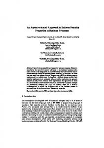
The logical modelling is done to visualize, specify and document the decisions about the domain vocabulary and about how these elements collaborate both structurally and from the behaviour point of view, but all this has been thought just for the basic functionality. To module aspects it seems clear to start from an architectural modelling in order to respect always the principal component in a system and control surely the aspectual components. Due to these and other needs it is recommended to use the directive about using the UML 2.0 Components diagram. «weaver»
general 0..*
4.6 Internal structures «aspect» logging
The components as well as all the classifiers have grown up due to a one of the new more important features in UML 2.0, the internal structures [8](p. 171-173). The Internal structure sub-package provides mechanisms to specify the interconnected elements structures that are created inside an instance of a container classifier. This kind of structure represents a decomposition of this classifier.
4.7 Property At the internal structures it is said that the property represents an instances group that are owned by a container classifier instance. When a container classifier instance is created, an instances group belonging to this properties can be created immediately or some time later. These instances are classifier instances that are typified by the property. A property specifies that an instances group can exist; this instances group is a subgroup from the total instances group specified by the typified classifier by the property. One part declares that an instance of this classifier can contain an instances group for composition. Everyone instances mentioned are destroyed when the container classifier instance is destroyed.
5. STARTING THE ASPECTS MODELLING WITH UML Finally, in this Section we try to satisfy the ACM needs using some new UML 2.0 concepts, achieving an approach to Aspects modelling with UML; furthermore, some initial directives will be propose in the AO systems modelling. In preceding researches it is been detected the first great aspects modelling directive [14]: the clear separation between Aspect and Basic-Module. This dichotomy is adopted as the main conceptual working framework that characterizes whatever is aspectsoriented. Although, in order to develop the UML aspects modelling, one more principle is established in this directive: An aspect must be considered as an encapsulated module separated from the main system, and separated too from the others aspects.
«aspect» synchronization
«aspect» distribution
«aspect» security
0..* «principal» functionality basic
Figure 2. Architectonical aspects modelling. In Figure 2 a system is depicted where the basic functionality is contained in a principal component named Basic Functionality; at the same time, the diagram encapsulates the functionality of each one of the Aspects in diverse components stereotyped as , denominating every component with the key name that describes the type of modelling Aspect. The manner in which the promised functionality will be provided will be mostly described with the internal structures of each component. The components diagram has represented too the ACM Weaver concept properties described in this paper. The weaver representation is shown with a component stereotyped as . An important consideration modelling is that the join points will be managed in the weaver component, outside the aspect components and the main component; so, this join points don’t belong individually to any of the concerns but they are used to indicate the crosscutting relationships between an aspect and a Basic-Module. The links between aspects and the main component show a dependency relationship with the weaver component. Although we must understand that the “join point” concept is really shaped along the whole architectural model described here. The general component has the commitment of identify and filter the join points where the code about the
6
different aspects inside the basic functionality main component will be applied, using the diverse aspect-components mechanisms. As a result, the aspect component is one support more for the dynamic and static join points management. In this architectural modelling we can observe the continuous use of Ports, all these elements are an important part in the different join points modelling found at the system. We must remember that in the AOP can be used different specialized languages for the aspects implementation. Actually the Aspects-oriented languages have a close relation with the ObjectsOriented languages, but this is not enough. Therefore, the AO modelling must be support by CASE tools in order to carry out the code in the different languages required for the AO systems implementation phase; in order to achieve this some facilities must be added in the tools to make specific languages patterns and not depend on duly provided languages, for the different Aspects.
5.2 Aspectual classes diagrams The class diagrams of the main component cannot module the relation between aspects and Basic-Module, due to the entanglement of relations that it would become, breaking the graphical representation harmony of the basic functional behaviour; although, it is recommended having a component classes visualization, specification, and documentation, which are cross and cut by different aspects. Hence, the AO modelling needs a complementary diagram. Class B - Attributes B + Operations
Class A
Class C
- Attributes A
- Attributes C
+ Operations
+ Operations
«aspect» crosscutting
Figure 3. Aspectual Classes Diagram. Figure 3 models an aspectual class diagram; the classes are connected with an association class by their respective Ports, the crosscutting association class is stereotyped as , since the association class is responsible of providing the changes to each one of the components classes in order to create objects with the necessary features to develop their basic functionality, achieving previously the modelling aspects weaving. In the UML 2.0 aspects modelling approach from this paper we present how the objects relationship in a basic functionality system is related ahead of time with aspectual instances for its later relation with objects just from the main component.
Thanks to the features in the association class, where it has class properties and hence it has the capability of generating roles, we can generate aspectual interaction diagrams.
5.3 Aspectual interaction diagrams The aspectual interaction diagrams (sequence and collaboration) will be important Aspects design weapon. These diagrams are the necessary supplement to describe the specific relationships between Aspects and Basic-Module. One circumstance that can appear is the possibility about an Aspect crosscutting other Aspect; in this case the aspectual interaction diagrams will need to show a relationship with elements from another aspect-component. However, the aspectual interaction diagrams between the aspects will be modulated in the main component, since this is the responsible to obtain consistency in these relationships, due to the possible multi-dimensional aspects [15] that can emerge in an AO system modelling.
6. CONCLUSIONS In this paper we introduced a comparison between an aspects theory proposed in the informal ACM with the UML 2.0 concepts than can be considered as Aspectual. The foregoing Section covers just one part of the directives that are necessary to module properly an AO system with an OO modelling language. This short work is just one step towards the goal of unifying the AOSD modelling concept. In this research we see that the Aspects incorporation in the software development process in the performing stage, can be handled in a discrete manner; it is notorious that module this Aspects using previously modelling languages, as well as with their respective and existing CASE tools, is more complex and needs more refinement. Actually few systems with great software quantity are using Aspects-Oriented modelling; the most of the software developers incorporate the AOP principles with AO languages, but it is more important to establish standards to develop Aspects during the software development life cycle and very specially at the design and requirements level. Still exist basic elements to be solved. A collective effort for such task would help to achieve this goal. In this context, the incoming work is a try of complete specification about the UML modelling language in order to provide notation and rules that enable the creation of structural and Aspectual behaviour models, where these would be treated explicitly as first class entities. Moreover we have the goal of develop a conceptual modelling for a possible evolution in the OO Programming, towards an Aspectual Objects-Oriented Programming – AOOP.
7
7. REFERENCES [1] Bertrand Meyer. Object-Oriented software construction, Prentice Hall PTR,1997 [2] Kiczales, G., Lamping, J., Mendhekar, A., Maeda, C., Lopes, Ch., Loingtier, J. and Irwin, J. Aspect-Oriented Programming. In Proceedings of the 11th European Conference on Object-Oriented Programming (ECOOP ´97) (Yväskylä, Finland, June 9-13, 1997). Springer-Verlag, Berlin Heidelberg, 1997, LNCS 1241, Pages 220–242. [3] The Aspect-Oriented Software Development web site. http://aosd.net/, July 2004. [4] Elrad, T., Filman, R. E., and Bader, A. Aspect-Oriented Programming: Introduction. Communications of the ACM, Volume 44, Issue 10 (October 2001), Pages 29–32. [5] Aldawud, O., Elrad, T. and Bader, A. Automatic code generation using an Aspect Oriented Framework. In Proceedings of the Workshop on Advanced Separation of Concerns at 15th European Conference on Object-Oriented Programming (ECOOP ’01) (Budapest, Hungary, June 1822, 2001). [6] Clarke, S., Harison, W., Ossher, H. and Tarr, P. Separation Concerns throughout the Development lifecycle. In Proceedings of the 3rd Workshop on Aspect-Oriented Programming at 13th European Conference on ObjectOriented Programming (ECOOP ’99) (Lisbon, Portugal, June 14-18, 1999) . [7] Object Management Group. Unified Modelling Language Specification. Version 1.5 March 2003 ( version 1.3 June 1999. Version 1.4 September 2001). [8] Object Management Group. UML 2.0 Infrastructure, UML 2.0 Superstructure Specification. OMG document ptc/03-0915. 2003. [9] Wegner, P. Dimensions of Object-based Language Design. In Proceedings 2nd Conference on Object-Oriented Programming Systems, Languages and Applications
(Orlando, Florida, United States, October 04 - 08, 1987). ACM Press, New York, NY, 1987, Pages 168-182. [10] Ossher, H. and Tarr, P. Operation-Level Composition: A Case in (Join) Point. In Proceedings of the 2nd Workshop on Aspect-Oriented Programming at 12th European Conference on Object-Oriented Programming(ECOOP ’98) (Brussels, Belgium, July 20-24, 1998). [11] Ostermann, K. and Kniesel, G. Independent Extensibility— An Open Challenge for AspectJ and Hyper/J. In Proceedings of the Workshop on Aspects and Dimensional of Concerns at 14th European Conference on Object-Oriented Programming (ECCOP ’00) (Sophia Antipolis and Cannes, France, June 12-16, 2000). [12] Matthijs, F., Joosen, W., Vanhaute, B., Robben, B. and Verbaeten, P. Aspects should not die. In Proceedings of the Workshop on Aspect-Oriented Programming at 11th European Conference on Object-Oriented Programming (ECCOP ’97) (Jyväskylä, Finland, June 9-13, 1997) [13] Stein, D., Hanenberg, S. and Unland, R. On Representing Join Points in the UML. In Proceedings of the 2nd Workshop on Aspect Modelling with UML at the Fifth International Conference on the Unified Modelling Language and its Applications (UML 2002), (Dresden, Germany, 30 September - 4 October, 2002). [14] Lamping, J. The Role of Base in Aspect-oriented Programming. In Proceedings of the 3rd Workshop on Aspect-Oriented Programming at 13th European Conference on Object-Oriented Programming (ECOOP ’99) (Lisbon, Portugal, June 14-18, 1999). [15] Tarr, P., Ossher, H., Harrison, W. and Sutton, S. M. Jr. N Degrees of Separation: Multi-Dimensional Separation of Concerns. In Proceedings of the 21st International Conference on Software Engineering (ICSE ’99) (Los Angeles, California, USA, May 16-22, 1999). IEEE Computer Society Press, Los Alamitos, CA, USA, 1999, pages 107–119.