An Architecturally-Integrated, Systems-Based Hazard Analysis for Medical Applications Sam Procter
John Hatcliff
Kansas State University
[email protected]
Kansas State University
[email protected]
Abstract—Medical devices are increasingly being developed not as standalone units but as network-aware machines that can be integrated via high-assurance middleware and coordinated with software into clinically useful applications for Medical Application Platforms (MAP apps). While this concept is still emerging, both regulators and vendors recognize that these apps can be as powerful as purpose-built medical devices, and they are struggling to understand the appropriate techniques to support risk assessment and safety claims. Before being approved for market, the reliability of medical devices is typically ascertained by performing one of a number of hardware-centric, reliabilityfocused analyses. However, these techniques are not a good fit for the combined hardware and software systems that are defined by MAP apps, nor is their emphasis on reliability appropriate when the end goal is safety. In this work, we tailor a modern, systems-based hazard analysis technique (STAMP / STPA) to the domain of MAP apps by leveraging our prior work in safety-critical systems engineering for medical software. We also build on our previously developed AADL-based language and tooling for the semi-formal modeling of MAP app architectures to provide a proof-of-concept tool that aids the transition between design and analysis. This tool takes as input an architectural model annotated with both new and re-purposed constructs from AADL (as well as its error modeling annex) and produces as output a report in our proposed format. We ground our approach by using a clinically-sourced scenario that serves as a motivating example: we provide an annotated architectural model and hazard analysis report that serve as exemplars of our technique and tooling.
I.
I NTRODUCTION
Medical device manufacturers, which have long developed their products as standalone units, are now beginning to develop devices capable of interacting with each other over a network. These interactions, which range from simple information-forwarding applications to sophisticated closedloop medical systems, have attracted increasing regulatory attention on a global basis. The resulting research has focused on a number of aspects of these “systems of systems” as well as the software platforms that enable them (termed medical application platforms, or MAPs[1]): the devices themselves, the software that governs their interactions (apps), as well as the underlying network infrastructure upon which the systems are composed. Additionally, there is an increasing understanding that the application of traditional system safety analysis techniques to the apps that run on these platforms is at best awkward and at times wholly inappropriate. Consider, for example, the “PCA Interlock” scenario described in Figure 1, which details a situation where a patient
A 49 year old woman underwent an uneventful operation. Postoperatively, the patient complained of severe pain and received intravenous morphine via a continuous infusion of morphine from a PCA pump. A few hours after leaving the post anesthesia care unit she was found pale with shallow breathing, a faint pulse, and pinpoint pupils. The nursing staff called a “code,” and the patient was resuscitated and transferred to the intensive care unit on a respirator. Based on family wishes, life support was withdrawn and the patient died. Review of the case by providers implicated a PCA overdose. Fig. 1.
An example STPA Report context, adapted from [2]
died due to the lack of interaction between her physiological monitors and her patient-controlled analgesia (PCA) pump. Had the monitors, typically a pulse oximeter (which tracks blood-oxygen saturation (SpO2 ) and pulse rate) and a capnograph (which monitors exhaled CO2 (EtCO2 ) and respiratory rate) been able to command the PCA pump to run at a minimal rate (i.e., form an interlock) via straightforward application logic, the patient’s life may have been saved. Though this application logic would not be difficult to develop, making a strong argument about the resulting system’s safety would be. Integrating the outputs of numerous devices, each of which can fail in a number of ways, to control a PCA pump which is itself fallible requires sophisticated error handling procedures. Since failure could mean serious injury or loss of life, a strong argument for safety must be made before the system is deployed. There exists work, by both regulators and researchers, on the architectural aspects of MAPs. ASTM International has developed their F2761-09 standard, which describes the functional architecture for an “Integrated Clinical Environment” (ICE) [3]. There have also been proposals for a MAPspecific architecture description language based on the Society of Automotive Engineer’s (SAE’s) Architecture Analysis and Description Language (AADL) [4]. What has not yet been addressed, though, is how best to argue for the safety of MAP apps. While some standards exist that address safety and risk management for medical devices and medical device software, (e.g., ISO 14971 and IEC 80001) most were written before the concepts of MAP apps and ICE were well known and may not be well-suited to the domain. What is needed, then, is a proposal for a hazard analy-
sis technique that is germane to MAP apps. Fortunately, a considerable amount of work in this area has already been done—a large number of hazard analyses (see, e.g., [5]) have been developed and refined over the years, and many are recommended (if not required) by medical device safety standards. However, since the field of hazard analysis continues to evolve (see, e.g., the Systems-Theoretic Accident Model and Processes (STAMP) and its associated hazard analysis technique, System-Theoretic Process Analysis (STPA) [6]), the issue of the most appropriate hazard analysis technique for MAP apps merits discussion. Further, many of the criticisms of existing hazard analyses such as informal (i.e., “word file”) formatting, manual construction, and a lack of integration with development artifacts [7] are especially problematic in the domain of MAP apps, as many of them tend to be relatively small, simple programs whose value lies partially in a quick time to market. In light of these issues, we present in this paper a description of work which integrates cutting-edge hazarddocumentation technologies with a similarly modern hazard analysis technique. Specifically, we describe the following contributions in this work: 1) A proposed format for MAP app hazard analysis which is based on the STAMP causality model and refined by our experience in the domain, and 2) An encoding of the information required by the report format from 1) using both AADL’s error-modeling (EMV2) annex and the AADL subset described in [4], and 3) An implementation of an automated translator that takes as input the EMV2 and AADL annotations from 2) and produces the report described in 1), and 4) A hazard analysis of the PCA Interlock MAP app, documented in the format described in 2) (which serves as expected input to our translator) and in the format described in 1) (which serves as expected output). The remainder of this paper is organized as follows. Section II describes the background of regulations and technologies relevant to this work. Section III explains our vision for a regulatory regime suited to MAP apps. Section IV describes our proposed STAMP-based report format. Section V describes our proposed use of EMV2 and the AADL subset from [4] as well as the tool which converts these annotations to our report format. In Section VI we conclude and discuss future work. II.
BACKGROUND
Like many interdisciplinary projects, our work is both informed and constrained by a number of different technologies. Some of these, like AADL, are quite close to core computer science topics (e.g., model-driven development) while others, like hazard analysis and the regulatory infrastructure, are external to the field. Though this can add an initial barrier to working in the domain [8], understanding the entire MAP ecosystem is vital to making an impact in the real world. A. Regulatory Authorities Hatcliff et al. explain that “. . . society’s confidence in safety-critical systems is typically established by government regulation, including requirements for licensing and certification” [8]. Relevant regulations include United States 21
C.F.R. §820.30(g) et seq. which specifies that “Each [medical device] manufacturer shall establish and maintain procedures for validating the device design. Design validation shall. . . include software validation and risk analysis, where appropriate.” Similarly, in the European Union, Council Directive 93/42/EEC Concerning Medical Devices states that “The manufacturer must lodge an application for assessment [which] must include. . . the design specifications, including the standards which will be applied and the results of the risk analysis.” The question then is, how is “risk analysis” evaluated? For the purpose of these regulations, typically a “mark” (e.g., CE) must be earned through the application of a relevant standard. For work in the medical device domain, this often means adherence to ISO 14971, which describes risk management for medical devices. When applied to software, application of ISO 14971 can be guided by the non-normative IEC 80001. There are a number of other relevant standards (e.g., IEC 62304: Medical device software – Software life cycle processes, IEC 60601: Medical electrical equipment, etc.) as well as emerging standards (e.g., AAMI/UL 2800: Interoperable Medical Device Interface Safety). Hatcliff et al. note later in [8] that “The presence of so many standards. . . can be bewildering to anybody operating in [the safety critical] domain, and can be a significant barrier in the education of new practitioners and researchers.” Indeed, we hope that our more formal, tool-supported efforts in this area can guide future revisions of related standards towards a more practicable approach. B. Hazard Analysis Techniques Underlying many of the previously mentioned riskmanagement standards are hazard analysis techniques. A number of broadly-applicable techniques have been developed and used successfully in range of safety-critical engineering domains. Two of the most common are Failure Modes and Effects Analysis (FMEA) and Fault Tree Analysis (FTA); a lesscommon third technique, STAMP/STPA, has been developed more recently. 1) Failure Modes and Effects Analysis: Originally developed in 1949 by the U.S. military, FMEA is a bottom-up analysis that considers the individual components (i.e. the hardware, software, or “functional” elements of a system) of a system and analyzes how they could fail [5]. Depending on the type of component under analysis, different failure mode keywords are suggested (e.g., for software components Ericson lists examples like “unsent messages” or “software hangs”) though practitioners will likely also want to introduce domain-specific failure modes as well. Table I shows an excerpted example of what an FMEA might look like for the PCA Interlock scenario, based on the format provided in [5]. It examines what might happen if the pulse oximeter fails to provide accurate SpO2 data to the application logic for various reasons. A full analysis would cover all required functionality for the scenario’s various subsystems (e.g., devices and application logic). Note that FMEA is primarily a reliability1 analysis that typically focuses on failures with a single cause, and it relies on experientially 1 As explained in [8], it is a common misconception that safety and reliability are synonymous. Reliability’s definition can be paraphrased as “ability to perform required functions” while safety is “freedom from harm.”
System: PCA Interlock FuncFailure tion Mode Provide Fails to SpO2 provide Provides late Provides wrong Analyst: Sam Procter
Failure Mode and Effects Analysis Subsystem: Pulse Oximeter Device Immediate System Method of Effect Effect Detection SpO2 not Unknown App reported patient state
Scenario Fail Causal Factors Rate N/A Network failure, device failure N/A
Network congestion, transient device failure
SpO2 not reported
N/A
Device error
SpO2 value Incorrect None incorrect patient state Date: September 26, 2014
TABLE I.
Unknown patient state
App
Current Controls
Hazard
Risk
Mode/Phase: Execution Recommended Action
Potential for overdose
3D
Default to KVO command
Potential for overdose
3C
Default to KVO command until new data arrive
Potential for overdose
1E
Have device report data quality with sensor reading Page: 3/14
E XCERPTS FROM AN EXAMPLE FMEA W ORKSHEET FOR THE PCA I NTERLOCK A PP
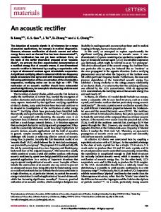
Too Large of Dose Allowed
Controlled Process: Pa:ent
G1
Bad Physiological Data Received G2
Incorrect Physiological Reading
G3
Message Garbled by Network
SoCware Encoding or Decoding Error Fig. 2.
Sensor: Pulse Oximeter Inadequate Opera-on: SpO2 value incorrect Inadequate Opera-on: SpO2 value late
Undetected Error
Controller: App Logic Process Model Incorrect: Wrongly believes pa:ent to be healthy Flaw in Crea-on: Messages are parsed incorrectly
Physiological Data within Max Range Internal DiagnosEcs Fail
An excerpt of an example fault tree
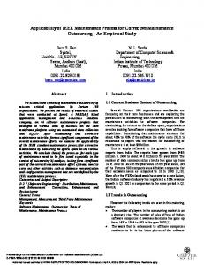
derived (typically published in aggregate) failure rates [9] that may not be available—or even appropriate—for purpose-built software components. 2) Fault Tree Analysis: Fault Tree Analysis is a top-down analysis technique that begins with a definition of an undesired event and then has the analyst consider what contributory faults could cause that event [5]. Unlike FMEA, FTA is a graphical analysis where faults are joined together (enabling the consideration of multiply-sourced failures) using logic gates (e.g., AND and OR) and can be repeated iteratively until a desired level of depth / rigor has been achieved. An excerpt of an example FTA for the PCA interlock scenario is shown in Figure 2. The top event corresponds to what should be avoided, and both of the contributory events (joined by AND-gate G1) must happen for the top-level event to occur. Only one of the contributory events joined by G2 would be necessary, though, as it is an OR-gate. A full FTA would likely trace down farther (i.e., it would include more levels of contributory events) and include a number of trees—one corresponding to each event or system state to be avoided. 3) STAMP / STPA: After examining a number of failings with safety-critical systems (and the engineering processes that guided their designs) Leveson recently (2011) described the Systems Theoretic Accident Model and Processes (STAMP) causality model and an associated hazard analysis, System Theoretic Process Analysis (STPA) [6]. As their names imply, STAMP and STPA differ most significantly from previous
Actuator: PCA Pump Inadequate Opera-on: Doesn’t respond to commands
Control Ac8on: PulseOx –> App Delayed opera-on: Messages late Missing feedback: Messages dropped
Fig. 3.
Control Ac8on: App –> PCA Pump Delayed opera-on: Messages late Missing feedback: Messages dropped
An example control loop annotated according to STPA
hazard analyses in their use of systems theory, which is defined by Leveson as an approach that “focuses on systems taken as a whole, not on the parts taken separately.” Unlike FMEA, which has component failures as its central notion, or FTA, which focuses on avoidance of certain events, STPA is driven by the avoidance of unsafe control actions (i.e., actions that can affect the state of the system). Once a list of unsafe control actions has been identified, potential causes can be analyzed and prevented / mitigated. A complete list of control actions can be automatically created given a thorough architectural description—reducing the hazard analysis expertise required and streamlining the development process. STPA contextualizes control actions by placing them in control loops, which by definition contain one or more a) actuators, b) sensors, c) controllers, and d) controlled processes. Figure 3 shows an excerpt of an annotated control loop for the PCA interlock scenario. Each element and link between elements is annotated with potentially unsafe actions; note the associated guide-phrases in italics. C. AADL The Architecture Analysis and Design Language (AADL) is a model-based architecture description language developed in 2004 by the Society of Automotive Engineers (SAE) [10]. It enables a developer to completely model a system’s architecture—from the software that performs the required functionality, to the hardware that the software runs on, as
well as the binding from the latter to the former. It is supported by a number of tools, including the open-source OSATE2, a powerful, Eclipse-based IDE, and has previously been used to describe and analyse medical device architectures [11], [12], [13]. In our previous work we have examined AADL’s applicability to MAP apps and identified a usable subset [4]. One reason that AADL is a particularly attractive language for describing safety-critical systems is because it has a number of language annexes that extend its modeling power to certain non-architectural system aspects. One such extension is the error modeling annex (in its second version, abbreviated EMV2) [14]. The error modeling annex, which is based on Wallace’s fault propagation and transformation language and algorithm [15], enables a developer to model error types, sources, propagations, behavior, detections, etc. Larson et al. have previously examined the application of EMV2 to a safetycritical medical device, and found that it enabled the realization of a number of benefits, including a) formal, machine-readable inputs, b) tight integration with the architectural model, and c) automated construction of FTA and FMEA-like reports [7]. III.
V ISION
The hazard analysis work here is a component of the larger app development environment (ADE) vision outlined in [4]. That vision lays out our plans for creating an ADE which supports all aspects of MAP-app development—including the creation of architectural, behavioral, hazard analysis, and safety-argumentation artifacts which will aid in the app’s regulatory approval process. A. Apps as System Integrators In traditional safety-critical development, a system’s various components are integrated by a systems expert before deployment. The MAP vision is unique, though, because while a MAP app’s functionality is safety-critical (that is, people may die as a result of errors), the system integration is specified by the app developer and the assembly is done at the time of app launch. That is, the app itself defines the system schematically by its set of assumptions and constraints. At app launch, the platform guarantees that an instantiation of this app meets these constraints. MAP apps specify the components (both software and hardware) used, as well as how those components are connected and any real-time or quality-of-service settings that are required for safety. This compositional style of construction requires a correspondingly compositional safety argument—if regulators were to only certify apps as safe when instantiated in certain exact configurations (i.e., with specific devices as opposed to types of devices), it would greatly limit the usefulness and impact of the MAP vision. Compositional hazard analysis is a complex problem, though, and one that has only recently begun to be addressed (see, e.g., [15]). We will address the full compositional safety vision elsewhere; in this paper we focus on hazard analysis activities that would be carried out within the app boundary.
STPA Report Format • Background: ◦ Clinical context ◦ Assumptions ◦ Abbreviations • Fundamentals: ◦ Accident levels ◦ Accidents ◦ System boundaries ◦ Hazards ◦ Safety constraints ◦ Control actions ◦ Control structure • Unsafe Control Actions: ◦ Causes and compensations Fig. 4.
The sections of the proposed STPA report format
analysis—involving not only the app’s software components but also the medical devices, composed system, and clinical process in which it would be used—is likely too high of a safety burden for app authors. Instead, we believe that most apps will be certified as members of app families (as in, AAMI/UL 2800, which addresses safety issues with the PCA interlock scenario) which will have notions of safety determined by standardization bodies. An app family would include things like devices and hardware components used, system-level hazards and safety constraints (to which app-level hazards and safety constraints would be traced), as well as the intended use of the app. IV.
STPA R EPORT F ORMAT
In Engineering a Safer World, Leveson presents a flexible, broadly-applicable hazard analysis that is suited to a range of safety-critical systems [6]. This original presentation is not tailored to any specific category of system, but since we know the various properties and architectural constraints of MAPs, we believe that the technique can be specialized somewhat to the domain. In particular, we believe that the somewhat prescriptive format presented here will provide guidance to analysts, and produce a more uniform final product. In this section we present a walkthrough of a proposed report format2 and associated process which apply both STPA and a number of lessons we have learned to the PCA interlock scenario. As discussed earlier, we will confine ourselves to notions of harm that are contributed to by the app itself. At a high level, the STPA-based report format we have developed is divided into three sections: a background, STPA fundamentals, and unsafe control actions and their causes (see Figure 4). A. Background
B. Envisioned Regulatory Regime
Though not mentioned in [6], we believe that before any actual hazard analysis is performed, it is important to contextualize the effort. This can be done with a brief narrative that introduces the scenario and explains the clinical need,
We believe that arguments for an app’s safety should come from first principles, but we recognize that a full system
2 Full report available HazardAnalysis.html
at:
http://santoslab.org/pub/mdcf-architect/
System Accident Levels 1) L1: A human is killed or seriously injured System Accidents 1) A1: Patient is killed or seriously injured [L1] App-Contributed Hazards 1) H1: Commands for dosage exceeding the patient’s tolerance are sent to the pump [A1] ,→ SH1: The pump administers more drug than the patient can safely tolerate. [A1] 2) H2: Incorrect information is sent to the display [A1] ,→ SH2: The clinician is misinformed of the patient’s health status. [A1] App Safety Constraints 1) C1: The app must command the pump to stop if the patient’s vital signs indicate over-infusion. [H1] ,→ SC1: The pump must not administer more drug than the patient can safely tolerate. [SH1] 2) C2: The app must inform the display of the status of the patient’s vital signs. [H2] ,→ SC2: The clinician must be informed of the patient’s status. [SH2] 3) C3: The app must inform the display of the pump command status. [H2] ,→ SC3: The clinician must be informed of the pump command status. [SH2] Fig. 5. Accident levels, accidents, hazards and constraints associated with the PCA interlock app and their system-level sources
as in Figure 1. After this context, standard front matter should be included: assumptions, abbreviations, and any other information necessary for an intended reader to understand the app. For the PCA interlock, we have one assumption: that our pump can run at either a normal rate or at a minimal KVO rate, and one abbreviation: KVO means “keep-vein-open.” B. Fundamentals After the background, a number of basic concepts need to be established before diving into hazard analysis. In her work, Leveson refers to these as fundamentals3 (see page 181 of [6]); in this paper we provide a set of examples tailored to the MAP domain. Specifically, our derivative, prescriptive format for report fundamentals is composed of: a) accident levels, b) accidents, c) system boundaries, d) hazards4 , e) safety constraints, f) control actions, and g) the control structure [6]. On page 181 of [6], Leveson explains that “[the] first step in any safety effort involves agreeing on the types of accidents or losses to be considered.” Figure 5 shows some fundamentals for the PCA interlock scenario, including both accidents and accident levels. Our one accident level is the loss of human life (other apps may need to consider things like, e.g., damage to equipment) and we have only one way that humans could 3 Note that Leveson’s definitions of these terms differ somewhat from standardized definitions used by medical risk-management standards. (e.g., those in ISO 14971). We use her definitions in this paper. 4 In the style of IEC 80001, we do not consider certain classes of hazards, e.g., electric shock. We assume that all devices used by our apps are IEC 60601 compliant, i.e., we only will be reasoning about newly-created hazards.
Process Boundary
Pa.ent
System Boundary Pulse Oximeter
Capnography Device
App Boundary
PCA Pump
App
Display
Clinician
Fig. 6.
The PCA interlock app, system and process boundaries
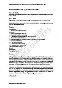
be harmed: if the pump administers too much drug (A1). How our app could cause this, though, depends on where we draw the app and system boundaries. Figure 6 shows the three boundaries present in the PCA interlock scenario. The outermost process boundary includes all scenario components, actors, as well as the clinical environment. The middle system boundary includes the system as defined by our app developer—all the devices and software components. The innermost app boundary includes only the messages sent to and from the software components developed by our app author. Once these boundaries have been established, Leveson says that the next step is to start identifying hazards, which she defines as “[a]. . . set of conditions that, together with a particular set of worst-case environmental conditions, will lead to an accident (loss).” We find that our app can cause accident A1 either by failing to stop the pump (H1 in Figure 5) or by misinforming the clinician of the patient or app status (H2). In order to prevent these hazards, we then establish safety constraints, which Leveson describes (on page 191 of [6]) as “. . . design constraints necessary to prevent the hazards from occurring.” Note that while accidents and accident levels are shared between a system and its components, the app will have its own hazards and safety constraints. These should be traced to their system-level source—shown in Figure 5 by the ,→ symbol. After the safety constraints have been identified, we are ready to identify the control actions and place them into the control structure as in Figure 7. Control actions are all the inputs and outputs of the system’s components, and typically include information on their range of possible values. For simple binary actions (e.g., “pump normal”/“pump KVO”) the values can be enumerated; for non-binary actions (denoted by a ? in Figure 7), a range of inputs should be defined: e.g., 0% < SpO2 < 100%. Once the control actions have been defined, the analyst should use them as labels on the communication links between system components. Next, the process model of the app should be broken down into its component variables,
★Physiological Status
Pa*ent Request More
App Physiological Data Status Healthy Overdosed Unknown Device Status Ok Error
Pump Normal Pump KVO
★ View Pa "Death or serious injury to a human"; ]
5 6 7 8 9 10
A1 : constant MAP_Error_Properties::Accident => [ Number => 1; Description => "Patient is killed or seriously injured."; Level => PCA_Shutoff_Error_Properties::AL1; ];
11 12 13 14 15
The use of EMV2—which enables developers to specify error causes, effects, and propagations in an AADL model—for MAP apps would bring a number of benefits, both those discussed in [7] (e.g., machine-readable inputs, close integration with the architectural model, automated report generation) and some degree of compositionality; since errors can be declared to propagate between components, we would move closer to the compositional vision described in Section III. That said, there are also disadvantages to applying the EMV2 language annex directly, primarily that EMV2 is designed for a) a bottom-up analysis style and b) older, potentially inappropriate hazard analyses (e.g., FMEA).
Accident : type record ( Number : aadlinteger; Description : aadlstring; Level : MAP_Error_Properties::Accident_Level; );
11
15
We have previously written about the subset of AADL we created to enable semi-formal descriptions of MAP app architectures and how these descriptions can be leveraged for code generation [4]. It seems natural to also evaluate additional capabilities of the language in light of other (i.e., non-architectural) desirable app design criteria. Chief among these is the desire for error modeling capabilities, particularly if those capabilities can be made to align with the STPA report format discussed in Section IV. Without this alignment, hazard analysis will remain an informal activity and the created artifacts will not be integrated with the app architecture.
Accident_Level : type record ( Level : aadlinteger; Description: aadlstring );
5
14
V.
Wrong Timing or Order N/A N/A N/A N/A Late: H1, H2
16
H1 : constant MAP_Error_Properties::Hazard => [ Number => 1; Description => "Commands for dosage exceeding the patient’ s tolerance are sent to the pump."; Accident => PCA_Shutoff_Error_Properties::A1; ];
17 18 19 20 21 22
H2 : constant MAP_Error_Properties::Hazard => [ Number => 2; Description => "Incorrect information is sent to the display."; Accident => PCA_Shutoff_Error_Properties::A1; ];
Fig. 10.
Uses of STPA fundamental properties in AADL
A. Annotation Walkthrough The process for annotating an architectural model is an iterative one, and one that is aided by tooling. We have developed our examples in OSATE2 as it provides rich support for modeling errors with EMV2. 1) Modeling Background and Fundamentals: Recall from Section IV-B that there are seven components of STPA’s “fundamentals,” ranging from accidents (and their associated severity levels) through the control structure of the system under review. Four of the first five fundamentals (accident levels, accidents, hazards and safety constraints) are essentially informal, plain-language statements that are organized in a hierarchical tree. We implemented these components using AADL’s built-in, extensible property notation. The result is a straightforward set of properties that can be quickly navigated using an AADL development tool like OSATE2 [11]. Elements of the background—context, abbreviations and assumptions— were also modeled as basic AADL properties, although their relations to one another form no particular structure. An excerpt of the property definitions we have created is
1 2 3 4 5 6 7 8 9 10 11 12 13 14 15 16 17 18 19 20 21 22
system implementation PCA_Interlock_System.imp subcomponents appLogic : process PCA_Interlock_Logic::InterlockProcess. imp; pcaPump : device PCAPump_Interface::PCAPumpInterface.imp; connections pump_cmd : port appLogic.cmd -> pcaPump.cmd; annex EMV2 {** use types PCA_Interlock_Errors; connection error od_cmd_err: error source pump_cmd; end connection; properties MAP_Error_Properties::Occurrence => [ Kind => AppliedTooLong; Hazard => PCA_Shutoff_Error_Properties::H1; ViolatedConstraint => PCA_Shutoff_Error_Properties::C1; Title => "Network Drop"; Cause => "Network drops out, leaving the pump running at the normal rate"; Compensation => "Pump commands have a maximum time, after which the pump runs at the KVO rate"; Impact => reference(CmdOD); ] applies to od_cmd_err; **};
Fig. 11. An excerpt of an AADL System Implementation component annotated with an EMV2 connection error and occurrence property
shown in Figure 9, and some example uses (corresponding to Figure 5) are presented in Figure 10. Lines 12-15 of Figure 9 specify the information required to define a hazard: a unique identifier (line 13), a human-readable description (line 14), and the accident that the hazard is associated with (line 15). Two uses of this definition are shown in lines 12-22 of Figure 10. 2) Generating the set of Control Actions: Since an app’s control actions are architectural constructs, they do not need to be specified as part of a hazard analysis. Rather, it is a straightforward process to identify an app’s control actions from an architectural model specified in the language from [4]. The control actions are equivalent to connections between components, as these specify the type, direction, and name of the control action. Unfortunately, the graphical nature of the system boundary and process model components of the report format from Section IV make auto-generation of these difficult,5 and for the time being, these must be created manually. Once created, they will be coupled with the automatically generated list of control actions and be included in the report generated by our translator. 3) Modeling Hazardous Control Actions and their Causes: Beginning with the first key realization discussed above (that port connections are equivalent to control actions), a natural starting point for documenting a STAMP-based hazard analysis is the EMV2 connection error construct, which enables a developer to specify a named error that can occur on a specific port connection. Once our potentially hazardous control action has been defined, we need to do three things: a) link it to the “fundamental” elements we have previously defined (e.g., accidents, hazards, constraints, etc.), b) define how it could occur, and c) specify the impact of the occurrence, i.e., how it will affect the system itself. All of these tasks are accomplished using a new property we have created, termed “occurrence,” an example of which 5 While there is a graphical editor for OSATE2, neither it nor AADL itself is designed to model the system environment / context (though there is work in this area, see [18]) nor are either designed to model relevant variable states (though again, behavior annexes exist [19], [20]).
Error Type
Renames Error Library Type Errors with Physiological Monitors LatePhysioDataError LateDelivery WrongPhysioDataError IncorrectValue PhysioDeviceFailure N/A Errors with Controlled Devices DeviceCommission ServiceCommission DeviceOmission ServiceOmission Errors with App Logic AppCommission ServiceCommission AppOmission ServiceOmission Errors with App Display WrongInfoDisplayedError N/A WrongInputReceivedError IncorrectValue TABLE IV.
MAP A PP E RRORS AND E RROR L IBRARY E QUIVALENTS
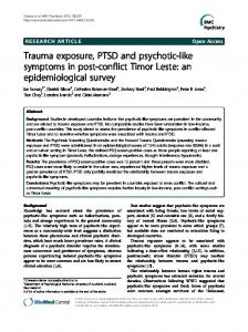
(corresponding to the “network drop” problem discussed in Section IV-D) is given in Figure 11. Lines 3-4 of Figure 11 specify our two components: a PCA pump and the application logic. They are connected via a port connection (line 6) which has an associated connection error named od_cmd_err (line 10). The occurrence property (lines 1321) then links a) the relevant fundamentals (lines 14-16) with b) human-readable information about the error (lines 17-19), c) the impact (line 20) and d) the associated connection error (line 21). Note that the occurrence in Figure 11 has been “designed out;” that is, it has a defined compensation that is reflected in the system’s architecture, and no longer poses the same risk. Other occurrences (e.g., boxes 2 and 4 in Figure 12—note the empty compensation component) may have no compensation, in which case the associated fault is still possible within the system. B. Integration with AADL EMV2 The “impact” component of the occurrence property (line 20 of Figure 11) contains a reference to an EMV2 error type. EMV2 error types inherit from a carefully constructed error type hierarchy [7], and as part of this work, we have defined a number of domain specific error types that we believe will be useful to MAP app developers (see Table IV). We expect that developers may want to extend or rename these types into app-specific errors. For example, the error type CmdOD on line 20 of Figure 11 extends from the MAP Error Type AppOmission which itself aliases the EMV2-standard error library type ServiceOmission. Once created as part of an occurrence property definition EMV2 error types should be fully traced through the system from their generative source, through any transformations, to their sink (shown graphically in Figure 12). While error type definitions are typically written in a separate file, their propagations must be attached to individual, affected components. These propagations follow a predictable pattern of first declaring a propagation direction (e.g., in or out) and then realizing the propagation with an error flow component (e.g., a source, transformation, or sink). For example, the SpO2ValueHigh error could occur in the pulse oximeter’s interface (box 1 in Figure 12) as an out propagation realized by a flow source. Error transformations, as their name implies, represent the conversion of one error type into another, as in box 3 of Figure 12. Note that in addition to the transformative flow specification there are two propagations:
Controlled Process: Pa0ent Sensor: Pulse Oximeter SpO2 reading high
1
error propagations SpO2: out propagation {SpO2High}; flows SpO2HighFlowSource: error source SpO2 end propagations;
3
5
Actuator: PCA Pump Con0nues pumping normally
error propagations PumpCmd: in propagation {CmdOD}; flows ODCmdFlow: error sink PumpCmd {CmdOD}; end propagations;
Controller: App Logic Believes pa0ent to be healthy, does not shut off pump
error propagations SpO2: in propagation {SpO2High}; PumpCommand: out propagation {CmdOD}; flows HighSpO2ToOD: error path SpO2{SpO2High} -> PumpCommand {CmdOD}; end propagations;
2
Control Ac8on: PulseOx –> App Wrong SpO2 Value sent to App Logic
connection error spo2_high_err: error source spo2_logic; end connection; properties MAP_Errors::Occurrence => [ Kind => TooHigh; Hazard => PCA_Error_Props::H1; Constraint => PCA_Error_Props::C1; Description => “Wrong values”; Cause => “Incorrect values are received from the physiological sensors”; Compensation => “???”; Impact => reference(SpO2High); ] applies to spo2_high_err;
Fig. 12.
4
Control Ac8on: App –> PCA Pump Shutoff command is not sent
connection error cmd_od_err: error source pumpcmd_logic; end connection; properties MAP_Errors::Occurrence => [ Kind => Providing; Hazard => PCA_Error_Props::H1; Constraint => PCA_Error_Props::C1; Description => “No shutoff command”; Cause => “App should command pump to shutoff, but it doesn’t”; Compensation => “???”; Impact => reference(CmdOD); ] applies to cmd_od_err;
A control loop annotated with a complete error trace
the consumption of the original error type (SpO2ValueHigh) and the production of the new error type (CmdOD). Finally, error sinks (box 5) have an in propagation with a corresponding sink flow. C. Putting it All Together The connection between a model’s architecture and the potentialities for unsafe control actions identified by STPA is formed via the “impact” sub-property (line 20 of Figure 11). More specifically, the impact of an occurrence must be an error type that is propagated between the two AADL constructs joined by the port connection that the occurrence property is applied to. Box 1 of Figure 12, the pulse oximeter, contains an EMV2 error source: it declares its SpO2 port to be a source of the SpO2High error; i.e., it is possible for its sensor to read incorrectly high SpO2 data from the patient. Box 2 is an occurrence property that documents this error, and links it to previously created hazards and constraints; it has SpO2High as its impact. Box 3, the app logic, declares the previously discussed error transformation. Box 4 is another example of an occurrence property; note that the “impact” component now references CmdOD—if this occurrence comes to pass, the result will be the app failing to shut down the pump even though the patient is showing signs of respiratory depression. Finally, box 5 is the PCA pump declaring an error sink for the CmdOD error, it is the final stopping point for this error chain. We believe that the feedback that OSATE2 provides when using these EMV2 annotations is an invaluable component of the hazard-documentation process. As unhandled incoming error propagations are recognized statically and highlighted in a similar fashion to syntax errors, it is our experience that developers will create an error type as the impact of
one hazard, but upon considering the effects of that error’s propagation to other—thought to be uninvolved—components discover additional hazards. This iterative interaction between the top-down, control-action focused STPA and the bottom-up, component-failure driven EMV2 drives the analysis forward. D. Report Generation Using as a base both OSATE2’s EMV2 support and the MAP app targeted subset of AADL and associated tooling described in [4], we have implemented a translator which takes as input an architectural model with the annotations described here and produces a report in the format described in Section IV. This translator is open-source, and is available as a plugin to OSATE26 . E. Comparison with Prior Approaches We believe that our proposed report format, when generated from the annotations discussed in this section, represents an advancement of the state of the art for hazard analysis of MAP apps. We now briefly compare our approach to the previously discussed hazard analyses. 1) Versus FMEA: Though FMEA has been in use for some time and has positive aspects, like its keyword-based guidance for analysts, there are a number of known problems with it. Ericson cites several, including a “[focus] on single failure modes rather than failure mode combinations” and a “[requirement of] expertise on the product or process under analysis” [5]. Additionally, at least one study has performed an in-depth gap analysis between a STAMP-based hazard analysis and one based on FMEA, and found that when analyzing a system the STAMP-based analysis identified more hazards (175 vs 70) including those that were “complex and nonlinear” yet still consumed “[considerably] less time and [fewer] resources” [21]. 2) Versus FTA: While FTA avoids many of the problems that affect FMEA, we believe our proposal still has some key advantages. One of the largest advantages comes from the keyword-based approach that the STAMP causality model advocates (and that we have encoded in our annotation definitions). We believe that these keywords, combined with the list of control actions that a developer gets “for free” by simply developing her architectural model in the supported AADL subset, will provide a straightforward set of potential faults that can be iterated over. In an FTA, however, analysts are given considerably less guidance. Events to be avoided are placed at the top level of fault trees and it is up to the analyst’s system understanding—and to some extent creativity—to determine the myriad ways that the failures can occur. VI.
C ONCLUSION
Our objective for this work, as described in Section I, was to a) describe a hazard analysis report format that would be both germane to MAP apps and based on the STAMP causality model, b) describe annotations in AADL’s EMV2 annex that would enable the encoding of the information required by the report, c) document a tool that will generate the report, and d) use as a motivating example the PCA interlock scenario. We believe our effort was, on the whole, successful. 6 http://santoslab.org/pub/mdcf-architect
R EFERENCES
A. Lessons Learned Perhaps the most pleasantly surprising result was how well the top-down approach of STPA and the bottom-up approach of EMV2 / FMEA can work together to iteratively drive not only the hazard analysis but the system design itself forward. The need for, and benefits of, this iteration are discussed in [6], and we believe our work in this area realizes and appropriately specializes Leveson’s work to the MAP app domain. With this work, our previous work [4] on semi-formal architectural specifications of MAP apps has begun to bear fruit. We believed that, in addition to the immediately realizable benefits like code generation and automatic interface conformance checking, there would be additional reason to define an app’s architecture in a subset of AADL. The ease with which some tasks in this work were accomplished, e.g., the identification of an app’s control actions, is validation of those beliefs. Additionally, some of what we learned reinforces the findings from [8], specifically that tooling and automation are vital to the development of safety-critical, software-dependent systems. That said, there were some problems encountered. Support for AADL’s EMV2 annex—as well as the language itself—is not yet mature; not only did we, in the course of developing our tool, have to submit a patch to the OSATE2 developers, but the annotation style can at times be awkward. Additionally, our report format currently relies on a number of graphical system layouts which we cannot automatically generate. This may impede the adoption of our report format and tooling.
[1]
[2]
[3]
[4]
[5] [6] [7]
[8]
[9] [10]
[11]
B. Future Work
[12]
Our next steps in this area will be to both inform and be informed by ongoing standardization and regulatory efforts. Though we believe our work can bring considerable safetycritical software engineering expertise to such groups, we are very much reliant on them for clinical experience and feedback. Additionally, it is through our efforts with these organizations that we expect to see the largest and most tangible results of this work. We also plan on examining other techniques previously used in system safety attestation, e.g., the construction of safety / assurance cases. The role of these techniques in future standards, research, and above all industry will largely be determined by how successful we (as a community) are at applying existing software engineering knowledge in the form of tool-supported processes for the development of safetycritical, software-based systems.
[13]
[14]
[15]
[16]
[17]
[18]
ACKNOWLEDGMENT This work is supported in part by the US National Science Foundation (NSF) (#1239543), the NSF US Food and Drug Administration Scholar-in-Residence Program (#1355778) and the National Institutes of Health / NIBIB Quantum Program. The authors also wish to thank Anura Fernando of Underwriters Laboratories for his feedback on an earlier version of this work.
[19]
[20]
[21]
J. Hatcliff, A. King, I. Lee, A. MacDonald, A. Fernando, M. Robkin, E. Vasserman, S. Weininger, and J. M. Goldman, “Rationale and architecture principles for medical application platforms,” in 2012 IEEE/ACM Third International Conference on Cyber-Physical Systems (ICCPS). IEEE, 2012, pp. 3–12. DocBox and MDPnP, “Clinical Scenario #1 Patient Controlled Analgesia Part 1: Narrative Description ,” National Institute of Biomedical Imaging & Bioengineering, Tech. Rep., August 2012. ASTM International, “ASTM F2761 - Medical Devices and Medical Systems - Essential safety requirements for equipment comprising the patient-centric integrated clinical environment (ICE),” ASTM International, West Conshohocken, PA, 2009. S. Procter, J. Hatcliff, and Robby, “Towards an AADL-Based Definition of App Architectures for Medical Application Platforms,” in Proceedings of the International Workshop on Software Engineering in Healthcare, Washington, DC, July 2014. C. A. Ericson II, Hazard analysis techniques for system safety. John Wiley & Sons, 2005. N. Leveson, Engineering a Safer World: Systems Thinking Applied to Safety. MIT Press, 2011. B. Larson, J. Hatcliff, K. Fowler, and J. Delange, “Illustrating the aadl error modeling annex (v. 2) using a simple safety-critical medical device,” in Proceedings of the 2013 ACM SIGAda annual conference on High Integrity Language Technology. ACM, 2013, pp. 65–84. J. Hatcliff, A. Wassyng, T. Kelly, C. Comar, and P. Jones, “Certifiably safe software-dependent systems: Challenges and directions,” in Proceedings of the on Future of Software Engineering. ACM, 2014, pp. 182–200. N. G. Leveson and J. Diaz-Herrera, Safeware: System Safety and Computers. Addison-Wesley Reading, 1995, vol. 680. P. H. Feiler, D. P. Gluch, and J. J. Hudak, “The Architecture Analysis & Design Language (AADL): An introduction,” DTIC Document, Tech. Rep., 2006. SEI, “An extensible open source aadl tool environment,” SEI AADL Team Technical Report, 2004. B. Kim, L. T. Phan, O. Sokolsky, and L. Lee, “Platform-dependent code generation for embedded real-time software,” in 2013 International Conference on Compilers, Architecture and Synthesis for Embedded Systems (CASES). IEEE, 2013, pp. 1–10. A. Murugesan, M. W. Whalen, S. Rayadurgam, and M. P. Heimdahl, “Compositional verification of a medical device system,” in Proceedings of the 2013 ACM SIGAda annual conference on High integrity language technology. ACM, 2013, pp. 51–64. SAE AS-2C Architecture Description Language Subcommittee, “SAE Architecture Analysis and Design Language (AADL) Annex Volume 3: Annex E: Error Model Annex,” SAE Aerospace, Tech. Rep., April 2013. M. Wallace, “Modular architectural representation and analysis of fault propagation and transformation,” Electronic Notes in Theoretical Computer Science, vol. 141, no. 3, pp. 53–71, 2005. J. Thomas and N. Leveson, “Performing hazard analysis on complex, software-and human-intensive systems,” in Proceedings of the 29th International Conference on Systems Safety, 2011. D. Arney, M. Pajic, J. M. Goldman, I. Lee, R. Mangharam, and O. Sokolsky, “Toward patient safety in closed-loop medical device systems,” in Proceedings of the 1st ACM/IEEE International Conference on Cyber-Physical Systems. ACM, 2010, pp. 139–148. Y. Qian, J. Liu, and X. Chen, “Hybrid AADL: A Sublanguage Extension to AADL,” in Proceedings of the 5th Asia-Pacific Symposium on Internetware, ser. Internetware ’13. New York, NY, USA: ACM, 2013. Carnegie Mellon University Software Engineering Institute. (2014) Graphical editor for osate. [Online]. Available: https://github.com/ osate/osate-ge SAE AS-2C Architecture Description Language Subcommittee, “SAE Architecture Analysis and Design Language (AADL) Annex Volume 2: Annex B: Behavior Annex,” SAE Aerospace, Tech. Rep., April 2011. V. H. Balgos, “A systems theoretic application to design for the safety of medical diagnostic devices,” Master’s thesis, MIT, 2012.