of those systems with other manufacturing software applications. ... of appropriate manufacturing strategies and the design of appropriate organizations and business ...... contain computer programs that are used to run machine tools and other ...
AN ARCHITECTURE AND INTERFACES FOR DISTRIBUTED MANUFACTURING SIMULATION
Charles McLean Frank Riddick Y. Tina Lee National Institute of Standards and Technology (NIST) Gaithersburg, MD (USA)
ABSTRACT
This paper presents an overview of a neutral reference architecture and data model for integrating distributed manufacturing simulation systems with each other, with other manufacturing software applications, and with manufacturing data repositories. Other manufacturing software applications include, but are not limited to systems used to: 1) design products, 2) specify processes, 3) engineer manufacturing systems, and 4) manage production. The architecture identifies the software building blocks and interfaces that will facilitate the integration of distributed simulation systems and enable the integration of those systems with other manufacturing software applications. The architecture builds on the High Level Architecture (HLA) standard for simulation (IEEE 2001). NIST and its collaborators have created several implementations of portions of the architecture using commercial off-the-shelf (COTS) simulators. These implementations demonstrated the feasibility of the architecture, and highlighted the need for a neutral data model for exchanging manufacturing data between simulations. Subsequent projects have focused on the development of a neutral information model for integrating machine shop software applications with simulation. The information model provides mechanisms for describing data about organizations, calendars, work, resources, schedules, parts, process plans, and layouts within a machine shop environment. The model has been developed using the Unified Modeling Language (UML) and the Extensible Markup Language (XML). The initial work on the architecture was undertaken as a part of the international Intelligent Manufacturing Systems (IMS) MISSION project. The neutral information model and interface specification activity was initiated under the Technology Insertion Demonstration and Evaluation (TIDE) project and is continuing as a collaboration activity under the Simulation Standards Consortium.
1 INTRODUCTION Scientists and engineers within the NIST Manufacturing Systems Integration Division of the Manufacturing Engineering Laboratory have developed an architecture for distributed manufacturing simulation in collaboration with representatives from a number of outside organizations. The organizations were principally participants in the IMS MISSION Project (MISSION Consortium 1998). MISSION is just one of many international, collaborative projects that have been conducted as part of the IMS Program. “The goal of MISSION was to integrate and utilize new, knowledge-aware technologies of distributed persistent data management, as well as conventional methods and tools, in various enterprise domains, to meet the needs of globally distributed enterprise modelling and simulation. This will make available methodologies and tools to support the definition of appropriate manufacturing strategies and the design of appropriate organizations and business processes. This goal will be achieved by establishing a modelling platform incorporating engineering knowledge and project information that supports space-wise and control-wise design, evaluation and implementation over the complete enterprise life cycle. This will be the foundation stone for an architecture to support engineering co-operation across the value chain of the entire extended enterprise.” (MISSION Consortium 1998)
NIST served as the U.S. Regional Coordinator for the IMS MISSION project. Participants on the U.S. MISSION team included NIST, the Defense Department’s Modeling and Simulation Office, a number of U.S. simulation software vendors, universities, and Black and Decker. For further information on the overall IMS Program, see the IMS Web page at . For information on research conducted by IMS MISSION collaborators from the European and Japanese regions see (Rabe et al. 2001), (Rabe and Jäkel 2001), (Hibino and Fukuda 2002), and (Hibino et al. 2001). Collaborators on the U.S. team jointly decided to focus on investigating two major research issues: 1) the feasibility of using the U.S. Department of Defense’s (DoD) High Level Architecture (HLA) for distributed manufacturing simulation, and 2) the development of manufacturing supply chain simulations. Prototype simulations were developed under the IMS MISSION project that demonstrated that various combinations of the commercial simulators of the project team could be interconnected under the architecture to construct distributed simulations. The interconnection process was simplified through the use of the NIST Distributed Manufacturing Simulation Adapter (DMS Adapter) software (Riddick 2004). With the DMS Adapter, the feasibility demonstrations were implemented with no changes to the internals of the commercial simulation engines. Time synchronization and data exchange were successfully demonstrated in several distributed supply chains simulation prototypes. Of the six different COTS simulation products used, each product was used in at least one implementation. A key reason for developing the DMS Adapter was to reduce the complexity in dealing with the HLA, which should foster greater use of distributed simulation technology in the manufacturing arena. In the HLA, data interfaces are specified in a Federation Object Model (FOM). Early in this work, it was recognized that the traditional approach to developing a FOM would need to be changed if the HLA technology were to be adopted by the manufacturing industry. NIST staff recommended that the Extensible Markup Language (XML) standards be used to encode data that would be exchanged between simulations in the future (Sall 2002). MISSION project participants recognized the need for information models for this data, but due to limited time and resources this aspect of the problem was not addressed. In a project initiated shortly after the completion of MISSION, NIST began working with collaborators on the development of neutral interfaces for exchanging manufacturing data between simulations and other applications. NIST staff believes that standard interfaces could help reduce the costs associated with simulation model construction and data exchange between simulation and other software applications -- and thus make simulation technology more affordable and accessible to a wide range of potential industrial users. Currently, small machine shops do not typically use simulation technology because of various difficulties and obstacles associated with model development and data translation. Small shops typically do not have staff with the appropriate technical qualifications required to develop custom simulations of their operations or custom translators to import their data from other software applications. NIST worked with a number of industrial partners and researchers to develop neutral formats for machine shop data to facilitate simulation and modeling activities. A machine shop data model, as a neutral interface format, has been under development to support both NIST’s System Integration of Manufacturing Application (SIMA) program and the Software Engineering Institute’s (SEI) Technology Insertion Demonstration and Evaluation (TIDE) Program. SIMA supports NIST projects in applying information technologies and standards-based approaches to manufacturing software integration problems (Carlisle and Fowler 2001). The TIDE Program is sponsored by the Department of Defense and SEI; it is currently engaged in a number of other projects with various small manufacturers in the Pittsburgh, Pennsylvania area. The technical work is being carried out as a collaboration between NIST, SEI, Carnegie Mellon University, Duquesne University, the iTAC Corporation, and the Kurt J. Lesker Company (KJLC). KJLC is an international manufacturer and distributor of vacuum products and systems to the research and industrial vacuum markets. KJLC manufactures complete, automatically controlled vacuum systems with special emphasis on customdesigned, thin film deposition systems for research in alloys, semiconductors, superconductors, optical and opto-electronics. A small machine shop is contained within the KJLC manufacturing facility. KJLC’s machine shop operation has been used to help define the requirements for simulation modeling and data interface specification activities described in this paper. Their facility will also be used as a pilot site for testing and evaluation of the simulation models, neutral data interfaces, and other software developed under this TIDE project. For more information on KJLC, see . The machine shop information model was developed with two goals in mind: a) support for the integration of software applications at a pilot facility -- KJLC’s machine shop, and b) promotion as a standard data interface for manufacturing simulators and possibly for other software applications. The information model is continuing to evolve based on experience and feedback from the KJLC’s implementation and from others involved in this effort. The information model provides a core set of data specifications that have applicability beyond the machine shop environment. Work on information modeling and the interface specification continues today. The objective of the information modeling effort is to develop a standardized, computer-interpretable representation that allows for exchange of information in a machine shop environment. The information model, when completed, must satisfy the following needs: support data requirements for the entire manufacturing life cycle, enable data exchange between simulation and other manufacturing software for machine shops, provide for the construction of machine shop simulators,
and support testing and evaluation of machine shops’ manufacturing software. Data structures contained within the information model include organizations, calendars, resources, parts, process plans, schedules, and work orders for machine shops. The remainder of the paper is organized as follows. Section 2 provides a summary of the architectural work completed as a part of MISSION. Issues concerning the distributed simulation architecture, the DMS adapter, and how HLA is related to this work are discussed. Section 3 provides an overview of the information modelling and interface specification activities that were undertaken after MISSION as a part of the NIST SIMA and SEI TIDE programs. In this section issues relating to the modelling tools and methodologies used are also discussed. In section 4, a synopsis of the information described in this paper is presented, along with a discussion of possible future research activities related to this work. 2 DISTRIBUTED MANUFACTURING SIMULATION ARCHITECTURE This document takes a broad view of distributed manufacturing simulation (DMS). Normally a DMS may be thought of as a manufacturing simulation that is comprised of multiple software processes that are independently executing and interacting with each other. Together, these simulation software processes may model something as large as a manufacturing supply chain down to something as small as an individual piece of industrial machinery. Different software vendors may have developed the basic underlying simulation software. The modules may run on different computer systems in geographically dispersed locations. The simulation may be distributed to take advantage of the functionality of specific vendor’s products, protect proprietary information associated with individual system models, and/or improve the overall execution speed of the simulation through the use of distributed computer processing. DMS may also refer to a distributed computing environment where non-simulation manufacturing software applications are running and interacting with one or more simulation systems. Engineering systems may interact with simulation systems through service requests. That is, they submit data to a simulator for evaluation. For example, a computer-aided manufacturing application that has generated a control program for a machine tool may submit that program to a simulator to verify that it is correct. Another view of DMS is a computer environment comprised of multiple, functional modules that together form what today is commonly a single simulation system. Such an environment may include model building tools, simulation engines, display systems, and output analysis software. 2.1
Why build distributed manufacturing simulation systems?
A distributed approach increases the functionality of simulation. For example, it could be used to • model supply chains across multiple businesses where some of the information about the inner workings of each organization may be hidden from other supply chain members • simulate multiple levels of manufacturing systems at different degrees of resolution such that lower level simulations generate information that feeds into higher levels • model multiple systems in a single factory with different simulation requirements such that an individual simulationvendor’s product does not provide the capabilities to model all areas of interest • allow a vendor to hide the internal workings of a simulation system through the creation of run-time simulators with limited functionality • create an array of low-cost, run-time, simulation models that can be integrated into larger models • take advantage of additional computing power, specific operating systems, or peripheral devices (e.g., virtual reality interfaces) afforded by distributing across multiple computer processors • provide simultaneous access to executing simulation models for users in different locations (collaborative work environments) • offer different types and numbers of software licenses for different functions supporting simulation activities (model building, visualization, execution, analysis). The next section outlines the role that software architectures will play in enabling the development of distributed manufacturing simulations. 2.2
Software Architecture
In their book, Software Architecture: Perspectives on an Emerging Discipline, Mary Shaw and David Garlan, explain the significance of software architectures:
“As the size and complexity of software systems increase, the design and specification of overall system structure become more significant issues than the choice of algorithms and data structures of computation. Structural issues include the organization of a system as a composition of components; global control structures; the protocols for communication, synchronization, and data access; the assignment of functionality to design elements; the composition of design elements; physical distribution; scaling and performance; dimensions of evolution; and selection among design alternatives. This is the software architecture level of design.”(Shaw and Garlan 1996) A distributed manufacturing simulation architecture is needed to address the integration problems that are currently faced by software vendors and industrial users of simulation technology. Neutral simulation interfaces would help reduce the cost of data importation and model sharing, and thus would make simulation technology more affordable to users. The definition of a neutral architecture for distributed manufacturing simulation is the first step towards identifying the information models, interfaces, and protocols for integrating these systems. This step can be achieved by decomposing the distributed manufacturing simulation architecture into three major functional views: Distributed Computing Systems, Simulation Systems, and Manufacturing Systems. Each architectural view defines a set of system elements, data models, and interface specifications for integrating distributed manufacturing simulations. Aspects of each view are interrelated to and interconnected with aspects of the other views. The views can be thought of as three sides of a cube. 2.3
Distributed Computing Systems View
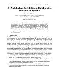
This architectural view is concerned primarily with simulation as a set of computers and software processes that are simultaneously executing and communicating with each other across a computer network. This view also addresses issues pertaining to the general management and integration of the software applications that are used to generate models and data for the simulations. The fact that the software processes are simulations or simulation-related is not particularly critical in this view. This view is not concerned with simulation or manufacturing data content. This view provides the infrastructure that allows us to implement simulation development and execution environments as distributed systems. Elements of this view include: hardware computing platforms, operating systems, distributed computer processes, integration infrastructures, process initialization and synchronization, software development environments (including but not limited to editors, compilers, system build utilities, debuggers, source code, general subroutine and header libraries, run-time modules, and system test data), communications systems, information models and data dictionaries, work flow management systems, database management systems and databases, product data management systems, version control and configuration management, computer file systems and files, system installation and maintenance utilities, computer security and data protection services, license verification systems, and World Wide Web access mechanisms. It also includes various input and output peripheral devices such as digital cameras, scanners, monitors, projection displays, printers, and virtual reality interfaces. There are five major clusters of information systems that are relevant to the distributed manufacturing simulation problem: 1) software development systems; 2) design, engineering, production planning, and simulation model development systems; 3) distributed manufacturing simulation execution systems; 4) manufacturing management, control, production, support systems, and 5) distributed manufacturing data repository systems. Figure 1 groups these systems into four computing environments and a shared, common data repository. The figure presents a logical grouping of system elements. Undoubtedly each implementation of this architecture will be based on
Software Development Environment
Design, Engineering, Production Planning and Simulation Model Development Environment
Distributed Manufacturing Simulation Execution Environment
Manufacturing Management, Control, Production and Support Systems Environment
Communications Network
Distributed Manufacturing Data Repository
Figure 1: Relationships Between The Major Elements Of The DMS Architecture
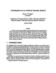
different information systems and physical configurations. The major elements of the figure are described briefly below. The Software Development Environment is used to develop simulation engines, visualization systems, integrating infrastructures, and other software applications. It is not the central focus of the architecture and will not be addressed in this paper. The Design, Engineering, Production Planning, and Simulation Model Development Environment contains the systems that generate models and data used by simulation and manufacturing itself. It is described in further detail below. The Distributed Manufacturing Simulation Execution Environment contains simulation engines executing models, visualization systems, and infrastructure systems to manage and integrate those simulations. The Manufacturing Management, Control, Production and Support Systems Environment is made up of the “real” systems that are used to run and perform the manufacturing operations. There are five component elements of the Design, Engineering, Production Planning, and Simulation Model Development Environment: 1) product design applications and tool kits; 2) manufacturing engineering applications and tool kits; 3) production management applications and tool kits; 4) simulation model development applications and tool kits, and 5) work flow management systems. In this environment, the work flow management system provides the integrating infrastructure. It manages and sequences activities within the applications and tool kits that generate manufacturing models and data. Tool kits are tightly coupled suites of applications that work together to perform a related set of functions. Tool kits may be manually driven or more automated expert systems. Product design applications may include conceptual and detailed design, solid modeling, bill of materials generation, design handbooks, parts catalogs, and various analysis tools. Some manufacturing engineering applications may include process planning and process specification, plant layout, machine tool programming, time standards development, line balancing, and tool and fixture design. Production management applications may include manufacturing resource planning, batch and lot sizing, and scheduling applications. Simulation model development tools include functions such as flowcharting, diagramming, model definition, and user level programming. A communications network connects environments with each other and the Manufacturing Data Repository. The Repository is a consolidation of the various data stores and management systems that are used by the various information systems environments. It logically integrates the file systems, Web pages, data bases, and libraries used for the storage of data by design, engineering, production planning, real manufacturing systems, simulation model development, and executing distributed manufacturing simulations. In different implementations of the architecture, the repository may reside on a single computer system, a file server, or be geographically distributed across a network. The Distributed Manufacturing Data Repository may include the following types of data stores and management systems: computer file systems, Web pages and files, object-oriented database management systems, relational database management systems, special-purpose library management systems, and source-code control systems for software. A common data access interface mechanism will be used to simplify access to the data repository by all software environments and applications within those environments. References to documents in the data repository may be specified as Uniform Resource Locators (URLs) see (Berners-Lee et al. 1998). This will allow the identification of documents, both remotely and locally stored using the well-established, standard, World Wide Web access mechanism. Figure 2 shows a decomposition of the Distributed Manufacturing Data Repository into its component elements. All of
Communications Network
Product Data Management System
PDMS Databases
Common Data Access Mechanism
Computer File System
Web Server
Object-Oriented Database Management System
Relational Database Management System
Special Purpose Library Management System
Software Source Code Control System
Web Files
Object-Oriented Databases
Relational Databases
Special Purpose Libraries
Software File System
Figure 2: Decomposition of the Distributed Manufacturing Data Repository
the types of data stores indicated in the figure do not necessarily have to be included in an implementation of the architecture. In the future, additional data management schemes and data stores may be added to the repository structure. From this point forward in this document, the Distributed Manufacturing Data Repository and Common Data Access Mechanism will be treated and represented as a single module. 2.4 Simulation Systems View This architectural view is concerned with the specifics of building, initializing, running, observing, interacting with, and analyzing simulations. In this view, simulation systems, tools, and supporting applications should be viewed generically; i.e., independent of the manufacturing domain. The same system elements could be used for simulating other problem domains. Major elements of this view include: simulation coordination and management, visualization systems, manufacturing data preparation and model development tools, simulation models, discrete event and process simulation engines, component module and template libraries, mathematical and analytical models, input distributions, timing and event calendars, and output analysis tools. Figure 3 illustrates the relationship between the various elements of the distributed manufacturing simulation execution environment. The integration infrastructure for this environment, the Run Time Infrastructure (RTI), is based on the U.S. Department of Defense High Level Architecture (HLA) developed by the Defense Modeling and Simulation Office (DMSO) (Kuhl et al. 1999). The HLA was developed by DMSO to provide a consistent approach for integrating distributed, defense simulations. Several implementations of the HLA RTI software are currently available from different sources. There is, however, no interoperability across RTI implementations. A distributed simulation running on different computer systems across a network must use the same RTI software as an integration infrastructure. An HLA-based distributed simulation is called a federation. Each simulator, visualization system, real production system, or output analysis system that is integrated by the HLA RTI is called a federate. One common data definition is created for domain data that is shared across the entire federation. It is called the federation object model (FOM). Each federate has a simulation object model that defines the elements of the FOM that it implements. A DMS Adapter Module is incorporated into each DMS federate. The DMS Adapter will handle the transmission, receipt, and internal updates to all FOM objects used by a federate. The DMS Adapter Module will contain a subroutine interface and data definition file that will facilitate its use as an integration mechanism by software developers. The goal of the DMS adapter is to ease the development of distributed manufacturing simulations by reusing implementations for some of the necessary housekeeping and administrative work. The DMS adapter provides a simplified time management interface, automatic storage for local object instances, management of lists of remote object instances of interest, management and
Simulation Visualization Federate
Manufacturing Simulation Federate
Real Manufacturing System Federate
Simulation Output Data Analysis Federate
DMS Adapter
DMS Adapter
DMS Adapter
DMS Adapter
Manufacturing Simulation Federation Manager
Distributed Manufacturing Data Repository HLA Run-Time Infrastructure and Communications Network
Figure 3: Distributed Manufacturing Simulation Environment Elements Integrated By The HLA Run Time Infrastructure
logging for interactions of interest, and simplified object and interaction filtering. Several functions may be needed for the proper operation of a distributed simulation that are logically outside of any one simulation federate. In the distributed manufacturing simulation environment, the Manufacturing Simulation Federation Manager is the architectural element that provides these functions. Its may implement functionality to execute initialization scripts that launch federates, to provide initialization data to federates, to assist in federation time management, and to provide a user interface so that users can monitor and manipulate the federation and invoke federation services. 2.5
Manufacturing Systems View
This architectural view is concerned with modeling the behavior and data of specific manufacturing organizations and systems, from the supply chain down to individual machines on the factory floor. Major elements of this view include, but are not limited to • manufacturing organizational templates and structures, business process and organizational models • supply chain systems - refineries, mills, factories, warehouses, distributors, transportation systems, wholesalers, retailers, customers • manufacturing facility departments, areas, and subsystems - design, engineering, procurement, finance, production shops, work cells, production lines, workstations, inventory storage areas, shipping and receiving • production resources and support equipment - machine tools, inspection equipment, material handling systems, storage buffers, robots, workers • tools and materials - cutting tools, hand tools, jigs and fixtures, consumables, components, part blanks, sheet and bar stock, work-in-process inventory • manufacturing information systems - design, engineering, production planning and scheduling, tool management, shop floor data collection systems • manufacturing documents and data - work flow patterns, orders, jobs, product data, part designs, process plans, production calendars, schedules, layouts, and other reference data (machinability data, statistical distributions) Different manufacturers will create different supply chain organizations and arrangements of systems within each organization. The DMS architecture must be flexible enough to allow these different system configurations, but still enable increased integration. As such, the architecture does not mandate a particular manufacturing organization. It does require the development and specification of one DMS FOM. Many objects in the FOM may reference documents containing more detailed information that are stored in a file system, PDM system, or database. An example of such a document might be a part design file or a process plan. The Extensible Markup Language (XML) can be used to define new document types (Goldfarb and Prescod 2000). XML allows for the definition of data that has semantic information in addition to the data values. A variety of schema languages can be used to to define new document formats. Advantages of this approach include: • the set of supported document types can be easily extended • each individual document format can be easily modified • COTS tools are available to implement creation, parsing, interpreting, and displaying the documents • XML documents from other sources can easily be supported • different instances of file structures may be created to convey the same semantic information • XML-enabled browsers can intelligently display the data • semantic validation of the files is possible. There are potentially many document types that will be stored as distributed manufacturing simulation data. Some of these document types have widely-accepted or standardized formats. Examples of these include the many kinds of CAD files (DXF, IGES, etc.), image files (GIF, TIFF, BMP, etc), and executables (EXE, com, bat, dll, etc.). However, many manufacturing documents do not have standardized format. Schedules, BOMs, and process plans are examples of such documents. While it is easy to come up with acceptable representations for such data that are appropriate for short-term use, it is highly likely that these representations will need modifications, possibly major modifications, over time. A mechanism is needed to allow the definition of extensible formats for new document types without adversely affecting the rest of the DMS architecture or interfaces. XML can be that mechanism. Schemas for the different document formats must be stored in and uniquely accessible from the DMS data repository. An initial set of document formats should be developed and allowed to expand over time as the need arises.
2.6 Integration via DMS Adapter and the HLA/RTI In the discussion and diagrams below, the changes necessary for integrating a legacy simulation into a distributed simulation using the HLA and the DMS Adapter will be discussed. The term legacy simulation is used to indicate a manufacturingoriented or general-purpose discrete-event simulation tool that does not have native support for the HLA or DMS Adapter technologies. Such systems are typically created using COTS simulation software packages. They may also be created from scratch using a combination of general-purpose and special-purpose computer programming languages.
Legacy Simulation Execution System Simulation Model
Legacy Simulation Execution System Federate Ambassador Implementation Custom Adaptation Code Simulation Model
HLA Runtime Infrastructure RTI Ambassador Federate Object Model
Legacy Simulation Persistant Storage
Legacy Simulation Persistant Storage
Figure 4: Simplified View Of A Typical Legacy Simulation System
Figure 5: Legacy Simulation Integration Using The HLA/ RTI
2.6.1 Simplified Simulation Execution Architecture In Figure 4, a simplified view of a non-distributed legacy simulation application is shown. It consists of a simulation execution system executing a simulation model. The simulation model is a behavior-oriented description of the logical system that is to be simulated. Simulation execution systems often support the visualization of the executing model and statistical reporting of the simulated events that are generated during execution. Data that are needed as input to or that are generated by the executing simulation are maintained in the persistent data store. 2.6.2 Integration using the HLA/RTI Figure 5 shows the architecture of a legacy simulation that has been integrated into a distributed simulation using the HLA. On the right side of the diagram, a simplified view of the HLA architecture is presented (constructs or concepts that are beyond the scope of this presentation have been left out for brevity). The Federate Object Model (FOM) is a description of the data that can be exchanged between federates. The FOM is usually different for each distributed simulation that is developed. The RTI Ambassador implements the interface through which federates send information to the RTI. This interface contains methods that provide the capability to manage federation creation, manage object class definitions, manage information exchange using objects and interactions, and manage the advancement of time for the federation. While the RTI Ambassador provides the mechanism for sending information to the RTI, an implementation of the Federate Ambassador interface is necessary to be able to receive information from the RTI. The Federate Ambassador is an interface that contains methods that define how the RTI sends information to a federate asynchronously in response to changes in the state of the federation. These state changes may be in response to calls to the methods on the RTI Ambassador
interface made by any federate in the federation. An implementation of the Federate Ambassador interface is not provided with the RTI software. The rules of the HLA require that an implementation of the Federate Ambassador be provided by the legacy simulation. Furthermore, this implementation must be consistent with the information defined in the FOM that is being used in this federation. 2.6.3 HLA/RTI Integration Issues Since legacy simulation systems are not designed to be used with the HLA/RTI, code must be developed to adapt the legacy simulation system for such purposes. Normally this code is complex. In addition, although some of the code can be reused, a significant amount of code will need to be added or modified for each distributed simulation that is developed. In the rest of this section, some of the important issues related to the complexity and reusability of the adaptation code are discussed. RTI Interface Complexity: There are roughly 120 methods in the RTI Ambassador interface and 40 methods in the Federate Ambassador interface. Depending on the current state of the RTI, the federation, and the data that is defined in the FOM, invoking a method can cause vastly different outcomes to occur. While the richness of the RTI's interfaces provide for an extremely flexible simulation integration approach, a side effect is that the learning curve for understanding these interfaces is quite high. The RTI's Implicit Invocation Architecture: The architecture of the RTI is based on what is called an "implicit invocation architecture." In this approach, a federate can modify the state of the federation by invoking methods of the RTI Ambassador interface. Information relating to changes in the state of the federation is passed back as asynchronous callbacks to methods in the Federate Ambassador that was implemented by the federate. While this is an efficient and flexible approach, it makes adapting legacy simulation difficult because legacy simulations usually provide only procedurally oriented mechanisms for integration. Inadequate Integration Mechanisms Are Provided By The Legacy Simulations: To use the interfaces of the RTI, some adaptation code must be written using a language supported by one of the RTI language mappings. Mappings currently exist for languages such as C, C++, Java, and CORBA IDL (Ben-Natan 1995). While some simulation systems provide mechanisms to call functions written in such languages natively, many do not. Integrating those legacy simulations usually requires a combination of proprietary-language code, file input/output, and socket programming, depending on which mechanisms are provided. This situation increases the complexity of developing and maintaining the adaptation code. Cooperative Time Management: In distributed simulations in which federates must cooperatively manage the advancement of time, the legacy simulation must be modified to cede some of the control over the advancement of time where previously it had complete control. Because the RTI provides multiple mechanisms for coordinating time advancement, choosing the appropriate mechanism and properly implementing the adaptation code to support it can require significant forethought and development. Storage And Maintenance For Instances Of FOM Objects: Many legacy simulations have internal representations for entities such as parts or machines, and these simulations can maintain the information about such entities as they are created during a simulation execution. The definitions of these entities will differ between different legacy simulations. To enable the exchange of data relating to these entities, neutral representations of these entities are usually defined in the FOM as object classes and associated attributes. However, the HLA/RTI provides no mechanism for storing object class instances. It only provides for storage of information related to the owner of a particular object instance, the class of the instance, and the attributes that are associated with an instance. Therefore, storage for instances of FOM objects must be provided by the legacy simulation. This is in addition to whatever storage has been set aside to maintain the legacy simulation's internal representation of an object. Adaptation code to maintain FOM object storage and to coordinate state changes between the internal representations and the FOM representations of objects must be developed. 2.6.4 Integration using the DMS Adapter In the previous section, some of the issues that are related to integrating legacy simulations using just the facilities of the HLA were discussed. It shows that developing the Federate Ambassador and adaptation code can be a significant undertaking when developing a distributed simulation, and that this effort must be repeated for each legacy simulation that is to be integrated. Figure 6 shows the architecture of a legacy simulation that has been integrated into a distributed simulation using the DMS Adapter. Instead of having legacy simulations integrated directly with the HLA/RTI, those simulations will interact with the interface of the adapter. The goal of the adapter is to provide a simplified method for integrating legacy simulations into distributed simulations while also providing as much of the capabilities of the HLA/RTI as possible. The reader should note that simplified does not imply simple. Adaptation code must still be developed to integrate a legacy simulation system
with the DMS Adapter. However, by reducing the complexity of the interface to which the legacy simulation is being integrated, the level of effort for performing the integration should be greatly reduced 2.6.5 Architectural goals for the DMS Adapter What follows is a list of design goals for the architecture of the DMS Adapter. If met, implementing distributed simulations using the DMS Adapter should be simpler than when using the approach that was depicted in Figure 5. Reduce interface complexity: The interface of the adapter will have approximately 35 methods instead of the 120 methods with 40 callbacks defined by the RTI and Federate Ambassadors. Remove Federate Ambassador implementation issues from the legacy simulation: Legacy simulations will not have to develop Federate Ambassador implementations. The adapter will implement a federate ambassador and use it to receive information from the RTI. Define an interface that facilitates integration with procedurally oriented legacy simulations: The results of invoking most of the methods in the adapter's interface will be returned immediately to the legacy simulation. Information that must be passed back asynchronously to a federate will be stored in a message queue in the adapter associated with that federate. This includes information that is generated by the activities of other federates in the federation. The adapter will provide the storage for this information and provide methods to access this information upon request from the legacy simulation. Minimize the impact of changes to the information model through the development of generic FOM objects that contain XML document fragments: To overcome the problem of having to develop different FOM's for each distributed simulation configuration, the information about the classes and attributes for the objects that are to be exchanged will not be defined in the FOM. A generic object class will be defined in the FOM and instances of this object will be exchanged between federates. This generic FOM object class will have an attribute of type string that is ment to hold an XML document fragment. The information will define the semantic content for the object. The XML document fragment is the information that will be passed to the legacy simulation. The generic FOM object class will also contain information about the type of data contained in the XML document fragment. This will facilitate filtering and routing of object updates by the RTI. There are five major benefits to this approach: 1. 2. 3. 4.
Only one FOM needs to be developed for use with the DMS Adapter. Only one implementation of the Federate Ambassador needs to be developed for use with the DMS Adapter. The DMS Adapter does not have to be modified and recompiled for each distributed simulation configuration. The information model (the definition of the entities, attributes and messages that will be exchanged between
Simulation Application and Models
Other Simulation Federates
Distributed Manufacturing Simulation Adapter
Federate A
Adapter Supervisor HLA Ambassador Adapter Interface Simulation Engine
RTI Services,
Run Time Infrastructure
Federate B
XML Parser/Generator Federate C
User Simulation Models and Data
Internal Simulation Object and Data Space
Common Data Access Mechanism Server Common Data Access Mechanism Transactions
Figure 6: Integrating Simulations Using The DMS Adapter
Distributed Manufacturing Data Repository
5.
simulations) can be changed without changing the FOM, Federate Ambassador implementation, or the DMS Adapter Implementation. Implementations of mechanisms for manipulating XML data are widely available and can be used in the development of both the DMS Adapter and the adaptation code for legacy simulations.
Maintain storage for the objects that are to be exchanged between simulations: As discussed in a previous section, the definition of an object (class and associated attributes) that is to be exchanged between simulations will differ from the internal definition that each simulation supports for that object. Since each legacy simulation only provides storage for its internal objects and the RTI provides no mechanism for the storage of objects, storage and maintenance for the objects that are to be exchanged must be provided. The DMS adapter will provide this capability. Each adapter will provide methods that allow a legacy simulation to create, modify, and delete objects that can be shared with other federates in the federation. Objects will have "owners", and ownership will be granted initially to the adapter (and associated legacy simulation) that created it. Ownership is required for modification or deletion operations on an object to succeed. Storage for "owned" objects will be provided by the DMS Adapter that owns the object. In addition, storage for copies of objects owned by other DMS Adapters will be provided. Each DMS Adapter will use the services of the RTI to distribute object update information for the objects it owns, and will incorporate object update information it receives about objects owned by other DMS Adapters. In this way, the DMS Adapters in the federation can work cooperatively to maintain updated information about all the objects in the federation, without the direct intervention of their associated legacy simulations. Simplify time coordination: The RTI provides a multitude of time synchronization methods that are extremely flexible and powerful but are also quite complicated. The adapter implements a "time- stepped" synchronization approach. DMS Adapter methods are provided to declare that the associated legacy simulation wishes to advance to a certain simulation time, and to check if it is ok to advance to this time. When the DMS Adapter indicates to the legacy simulation that it is ok to advance, the legacy simulation can then "simulate" from its current simulation time to the new simulation time that it requested. It can then use the other methods in the DMS Adapter interface to get information about what was going in the rest of the federation while it was executing its "simulation step." When all of the simulations use this method, the functionality of the RTI's time management services ensures that the collective advancement of all of the simulations proceeds properly. While meeting the architectural goals for developing the DMS Adapter will provide a mechanism for exchanging information between manufacturing simulation applications, for meaningful information exchange to take place, the semantic content of the information to be exchanged must be defined. In the next section, the development of an information model that defines the semantics for the meaningful exchange of manufacturing simulation related information is discussed. 3
MANUFACTURING SIMULATION INTERFACE SPECIFICATIONS
An information model provides a sharable, stable, and organized representation of information in a selected domain area. The Integrated Computer Aided Manufacturing (ICAM) Definition Language 1 Extended (IDEF1X), EXPRESS, Unified Modeling Language (UML), and XML are most often used by the manufacturing enterprises for information modeling. IDEF1X is a formal graphical language for relational data modeling, developed by the U. S. Air Force (Appleton 1985). EXPRESS (ISO 1994b) was designed to meet the needs of the STandard for the Exchange of Product model data, commonly called STEP (ISO 1994a), and it has been used in a variety of other “large-scale” modeling applications. UML is a graphic representation for artifacts in software systems, and is also useful for database design (OMG 2003). XML is a format for structured documents and it helps make possible information exchange in a globally distributed computing environment (W3C 2000). Section 3.1 of this document provides an overview of the concept behind the machine shop information model. Section 3.2 explains the constructs used to define the information model, how the model will be used, and gives some detailed examples of a small portion of the model. 3.1
Concept For The Data Model
In this section, the concept of the shop information model is introduced from the user perspective. The primary objective was to develop a structure for exchanging shop data between various manufacturing software applications, including simulation. The idea was to use the same data structures for managing actual production operations and simulating the machine shop. The rationale was that if one structure can serve both purposes, the need for translation and abstraction of the real data would
be minimized when simulations are constructed. The mapping of real world data into simulation abstractions is not, for the most part, addressed in the current data model. Maintaining data integrity and minimizing the duplication of data are important requirements. For this reason, each unique piece of information appears in only one place in the model. Cross-reference links are used to avoid the creation of redundant copies of data. The machine shop data model contains twenty major elements. Each of the major data elements are italicized in the discussion that follows. The data elements are called: organizations, calendars, resources, skill-definitions, setup-definitions, operation-definitions, maintenance-definitions, layout, parts, bills-of-materials, inventory, procurements, process-plans, work, schedules, revisions, time-sheets, probability-distributions, references, and units-of-measurement. Figure 7 illustrates some of the major elements of the conceptual data model and their relationships to each other. Due to space limitations, the entire model is not shown or discussed in detail. For more detailed information on the model, see (McLean et al. 2003). The remainder of this section discusses the data elements and their significance. Perhaps a good place to start the discussion of the data model is with the customer. Machine shops are businesses. They typically produce machined parts for either internal or external customers. Data elements are needed to maintain information on customers. The types of organizational information that is needed about customers is very similar to the data needed about suppliers that provide materials to the shop. The same types of organizational data are also needed about the machine shop itself. For this reason, an organizations element was created to maintain organizational and contact information on the shop, its customers, and its suppliers. Organizations can be thought of as both a phone book and an organization chart. The element provides sub-elements for identifying departments, their relationships to each other, individuals within departments, and their contact information. Various other types of information needs to be cross-referenced to organizations and contacts within structure, e.g., customer orders, parts, and procurements to suppliers. The operation of the machine shop revolves around the production of parts, i.e., the fabrication of parts from raw materials such as metal or plastic. The raw materials typically come in the form of blocks, bars, sheets, forgings, or castings. These materials are themselves parts that are procured from suppliers. The parts data element was created to maintain the broad range of information that is needed about each part that is handled by the machine shop. Part data includes an identifying part number, name, description, size, weight, material composition, unit-of-issue, cost, group technology classification codes, and revision (change) data. Cross-reference links are needed to the customers that buy the parts from the shop and/or the suppliers that provide them as raw materials. Links are also needed to other data elements, documents, and
customers inventory place defined by
organizations has
time sheets
calendars
use
provide requirements
specify may result identify
schedules
produced by work
specification provided by decompose locate
assign resources
employ skill definitions
production process defined by
parts
procurements
maintain
have
process plans
assemblied by
supply
receive
store
purchase
suppliers
bills-ofmaterials
employees
maintenance definitions
maintenance requirements defined by
machines
setup definitions
machine setups defined by
stations
may include
machine programs may have
station operations defined by high-level production processes defined by orders
operation sheets may have
routing sheets
activity defined by
consist layout jobs
ability defined by
machine control defined by
required by
consist tasks
.....
Figure 7: Concept For The Machine Shop Data Model
defined by
operation definitions defined by
files that are related to the production of parts including: part specification documents, geometric models, drawings, bills-ofmaterials, and process plans. The bills-of-materials element is basically a collection of hierarchically-structured parts lists. It is used to define the parts and subassemblies that make up higher level part assemblies. A bill-of-materials identifies, by a part number reference link, the component or subassembly required at each level of assembly. The quantity required for each part is also indicated. Cross-references links are needed between parts that are assemblies and their associated bill-of-materials. The parts and bills-of-materials elements establish the basic definition of parts produced or used by the shop. Another element, inventory, is used to identify quantity of part instances at each location within the facility. Inventory data elements are provided for parts, tools, fixtures, and materials. Materials are defined as various types of stock that may be partially consumed in production, e.g., sheets, bars, and rolls. Structures are provided within inventory to keep track of various stock levels (e.g., reorder point level) and the specific instances of parts that are used in assemblies. The procurements element identifies the internal and external purchase orders that have been created to satisfy order or part inventory requirements. Cross-reference links are defined to parts to identify the specific parts that are being procured and to work to indicate which work items they will be used to satisfy. The work data element is used to specify a hierarchical collection of work items that define orders, production and support activities within the shop. Support activities include maintenance, inventory picking, and fixture/tool preparation. work is broken down hierarchically into orders, jobs, and tasks. Orders may be either customer orders for products or internally-generated orders to satisfy part requirements within the company, e.g., maintenance of inventory levels of stock items sold through a catalog. Orders contain both definition and status information. Definition information specifies who the order is for (i.e., customer cross-references), its relative priority, critical due dates, what output products are required (a list of order items, i.e., part references and quantities required), special resource requirements, precedence relationships on the processing of order items, and a summary of estimated and actual costs. Order items are also cross-referenced to jobs and tasks that decompose the orders into individual process steps performed at workstations within the shop. Status information includes data about scheduled and actual progress towards completing the order. Jobs typically define complex production work items that involve activities at multiple stations and ultimately produce parts. Tasks are lower level work items that are typically performed at a single workstation or area within the shop. The process-plans element contains the process specifications that describe how production and support work is to be performed in the shop. Major elements contained within process-plans include routing sheets, operation sheets, and equipment programs. Routing and operation sheets are the plans used to define job and task level work items, respectively, in the work hierarchy. These process plans define the steps, precedence constraints between steps, and resources required to produce parts and perform support activities. Precedence constraints defined in a process plan are used to establish precedence relationships between jobs and tasks. Equipment program elements establish cross reference links to files that contain computer programs that are used to run machine tools and other programmable equipment that process specific parts. Each part in the parts element contains cross-reference links to the process plans that define how to make that part. Jobs and tasks contain links back to the process plans that defined them. The resources element is used to define production and support resources that may be assigned to jobs or tasks in the shop, their status, and scheduled assignments to specific work items. The resource types available in the machine shop environment include: stations and machines, cranes, employees, tool and tool sets, fixtures and fixture sets. The skill-definitions, setup-definitions, operations-definitions, maintenance-definitions, and time-sheets elements provide additional supporting information associated with resources. Skill-definitions lists the skills that an employee may possess and the levels of proficiency associated with these skills. Skills are referenced in employee resource requirements contained in process plans. Setup-definitions typically specifies tool or fixture setups on a machine. Tool setups are typically the tools that are required in the tool magazine. Fixture setups are work-holding devices mounted on the machine. Setups may also apply to cranes or stations. Operation-definitions specifies the types of operations that may be performed at a particular station or group of stations within the shop. Maintenance-definitions specifies preventive or corrective maintenance to be done on machines or other maintained resources. Time-sheets is used to log individual employee’s work hours, leave hours, overtime hours, etc. The layout element defines the physical locations of resource objects and part instances within the shop. It also defines reference points, area boundaries, paths, etc. It contains references to external files that are used to further define resource and part objects using appropriate graphics standards. Cross-references links are also provided between layout objects and the actual resources that they represent. Schedules and calendars data elements are used to deal with time. Schedules provides two views of the planned assignment of work and resources. Work items (orders, jobs, and tasks) are mapped to resources, and conversely, resources are mapped to work items. The planned time events associated with those mappings are also identified, e.g., scheduled start
times and end times. Calendars identifies scheduled work days for the shop, the shift schedules that are in effect for periods of time, planned breaks, and holiday periods. The four remaining major data elements are revisions, references, probability-distributions, and units-of-measurement. The revisions element is used repeatedly throughout many levels of the data model. It provides a mechanism for identifying versions of subsets of the data, revision dates, and the creator of the data. The references element identifies external digital files and paper documents that support and further define the data elements contained within the shop data structure. It provides a mechanism for linking to outside files that conform to various other format specifications or standards, e.g., STEP part design files. The probability-distributions element defines probability distributions that are used to vary processing times, breakdown and repair times, availability of resources, etc. Distributions may be cross-referenced from elsewhere in the model, e.g., equipment resources maintenance data. Units-of-measurement specifies the units used in the file for various quantities such as length, weight, currency, and speed. The next section provides a detailed illustration of a small portion of the overall data model, and UML and XML file structures. 3.2
Specification Of The Information Model
An information model is a representation of concepts, relationships, constraints, rules, and operations to specify data semantics for a chosen domain of discourse. The advantage of using an information model is that it can provide shareable, stable, and organized structure of information requirements for the domain context. An information model serves as a medium for transferring data among computer systems that have some degree of compliance with this information model. For proprietary data, implementation-specific arrangements can be made when transferring those data (Lee 1999). In general, the contents of an information model include a scope, a set of information requirements, and a specification. Information requirements serve as the foundation of the specification of the information model. A thorough requirements analysis is a necessity. The initial goal for the machine shop information model is to support data transferring needed for KJLC’s machine shop operations. This information model, ultimately, will be promoted as a standard data interface to be used by other machine shops. Thus, the completeness and correctness of the information requirements and a consensus on the data requirements from the industry are also important issues. The specification of the information model defines elements, attributes, constraints, and relationship between elements for the domain context. The specification should be laid out using some formal information modeling language. An information modeling language provides a formal syntax that allows users to unambiguously capture data semantics and constraints. Three types of methods that implement information models are currently used by the manufacturing community: • Data transfer via a working form, which is a structured, in-memory representation of data. The method uses a mechanism that accesses and changes data sequentially without actually moving the data around. All shared data are stored in memory. • Data transfer via an exchange file, which is a file with a predefined structure or format. This method requires a neutral file format for storing the data. The application systems read and write from files. • Data transfer using a database management system. This method uses a database management system where information is mapped onto and retrieved from databases. These implementation methods can be accomplished through translators that are developed using programming languages and database management systems. The selection of an implementation method is heavily dependent on the target environment where the application system resides. While the relational database is generally desirable for data transfer, the traditional file-oriented systems are being used continually by many manufacturing applications. A specification for the machine shop information model has been developed based on the data model concept described in Section 3.1. The shop-data element, the top-level element in the model, is represented by an identifier and a number. Optional elements include: type, name, description, reference-keys, revisions, units-of-measurement, organizations, calendars, resources, skill-definitions, setup-definitions, operation-definitions, maintenance-definitions, layout, parts, billsof-materials, inventory, procurements, process-plans, work, schedules, time-sheets, references, and probability-distributions. Type is an attribute of shop-data and is an enumeration to describe types about shop-data. Identifier is a key to uniquely identify the object internally within the system, and it is generated automatically by the system when the object is created. Number is also a unique key for identifying the object either when taken alone or possibly together with the object type, and the uniqueness is to the user or the user’s organization. Identifier and number are required attributes. Name is used to identify the object by the user or user’s organization. It is provided for readability sake. Description is used to describe the nature of the subject. Reference-keys refers to reference documents or files that are stored external to the model. When a data element’s name suffixes with “-key” or “-keys”, these data elements serve as pointers to the model to avoid redefining the same set of information. All other attributes, such as organizations, calendars, resources, etc., are major elements of the model that were introduced in Section 3.1.
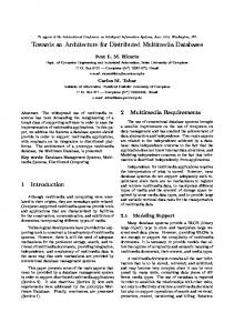
The machine shop data model specification is documented using both UML and XML structures. XML is chosen to support web users while UML’s standard graphical notations provide visual communications. UML is a graphical representation; the language is for specifying, visualizing, constructing, and documenting, rather than processing. XML is a format for structured documents, thus XML documents are decodable. The current version of the specification includes XML documents that are well-formed, but may or may not be validated. Data should be validated before being imported to a legacy system. An XML schema is a specification of the elements, attributes, and structures; it is not only useful for documentation, but also for validation or processing automation (van der Vlist 2002). To facilitate automated validation, the format of the XML documents that make up the specification will be defined using the World Wide Web Consortium (W3C) XML Schema, an XML Schema language. UML provides several modeling types, from functional requirements and activity analysis to class structures and component description. The modeling type used to map to the XML documents is the UML class diagram. A UML class diagram can be constructed to visually represent the structural and behavioural features. Since the behavioural feature is not relevant to the XML specification, that feature is omitted here (Carlson 2001). The complete specification is not given here due to its size. Instead a sample data element specification is described. The data element of orders is chosen for illustration in this section, see Figure 8. Orders is a subgroup of work and consists of a set of individual order data elements. It specifies a collection of production work orders to be processed within the shop. Each order contains the order definition and/or order status section. The order definition contains attributes of the order including a list of order items, i.e., a listing of individual parts that make up a particular order. The order status describes information about scheduled and actual progress toward completing the order. The same part may be listed in the order multiple times in different order items if each instance has unique attributes, e.g., different due dates. shop-data -type[0..1] -identifier[1] -number[1] -name[0..1] -description[0..1] -REFERENCE-KEYS[0..1] -REVISIONS[0..1] -UNITS-OF-MEASUREMENT[0..1]
work
performs 1 0..1
-type[0..1] -identifier[1] -number [1] -name[0..1] -description[0..1] -REFERENCE-KEYS[0..1] -REVISIONS[0..1]
specifies
0..1
1 orders -type[0..1] : String -identifier[1] : int -number[1] : String -name[0..1] : String -description[0..1] : String -REFERENCE-KEYS[0..1] -REVISIONS[0..1] 1
order-definition
contains
defined by
1..* 0..1
order -type[0..1] : String -identifier[1] : int -number[1] : String -name[0..1] : String -description[0..1] : String -REFERENCE-KEYS[0..1] -REVISIONS[0..1]
-CUSTOMERS[1] -priority-rating[0..1] : String -DUE-DATES[1] -ORDER-ITEMS[0..1] -PRECEDENT-CONSTRAINTS[0..1] -RESOURCES-REQUIRED[0..1] -COST-SUMMARY[0..1]
1
has
order-status 0..1
-WORK-SCHEDULED-PROGRESS[0..1] -WORK-ACTUAL-PROGRESS[0..1]
Figure 8: UML Model Of The Orders Object
3.2.1 UML Modeling As mentioned before, the UML class diagram is one representation for the specification of the information model. A number of software tools are available for generating UML diagrams. The UML class diagrams introduced here have been generated using Microsoft Visio 2000. A UML class diagram can be constructed to graphically represent the classes, attributes, and relationships. A UML class is the abstraction of a concept in the domain of discourse; it is defined by a set of attributes. An attribute is an additional piece of information associated with a UML class. Each attribute defines its type (such as string, integer, date, or user defined data type), relationships, and optionally specifies its default value. A special type of class, named DataType, is used to specify enumeration items. Relationships between classes are shown with the connecting line; the role and cardinality relationship may be presented along the relationship line. The role describes how the related class is used. There exist cardinality relationships between a class and its attributes, and between classes. The cardinality relationship specifies how many specific instances of an element could be related to another element. The cardinality relationship may be “one” to “zero or one”, “one” to “zero or more”, “one” to “one or more”, or exactly “n” occurrences, and is presented in the Figure 8 as 0..1, 0..*, 1..*, n, respectively. The cardinality relationship used for attributes is enclosed by [ ]. The UML information model for the orders element is shown in Figure 8. The orders element is a sub-element of the work element, which is a sub-element of the shop-data element, which is the top element of the model. The orders element has the attributes of type (which is an optional string), an identifier (which is an “int” or integer value), a number (which is a string), an optional name (which is a string), an optional description (which is a string), and an optional reference-keys and revisions (they are user defined data types). Figure 8 illustrates the role and cardinality relationships among orders, order, order-definition, and order-status. An orders element contains order elements. Each order is defined by order-definition and has an order-status. Orders and order have a “one” to “one or more” relationship, i.e., there may exist one or many order instances for an orders instance. Similarly, there may exist zero or one order-definition instance and zero or one order-status instance for an order instance. Each order-definition instance is defined by one customers instance, one due-dates instance, and zero or one of priority-rating, order-items, precedent-constraints, resources-required, and cost-summary instances. 3.2.2 XML Specification XML supports the development of structured, hierarchical data entities that may contain a high level of semantic content, that is both human and machine interpretable. There are several supporting standards from W3C that make working with XML easier. These include Document Object Management (DOM) for manipulating XML documents, XML Schema for defining the format of XML documents, and Extensible Style-sheet Language (XSL) for translating XML documents to other formats, see . There also exist a wide variety of software applications to implement creation, parsing, interpreting, and displaying of XML documents. An XML document is a collection of parsed and unparsed pieces. An element is one of the basic type of nodes in the tree represented by an XML document. A well-formed document has one unique root element that contains all other elements. Elements follow one another, or appear inside one another, but may not overlap. All elements must have a start-tag and an end-tag that surround their contents. An element begins with (that is a start-tag) and ends with (that is an end-tag). XML is case-sensitive. The contents of each element may include other elements. An XML element may be defined by a set of attributes and child-elements. Attributes and child-elements are additional information associated with the element. Attributes are presented in the start-tag, in the form: . The same attribute can appear inside the start-tag once only. However, the same child-element may appear in the element more than once if it carries different instances. Attributes are unordered while child-elements are presented in order. When an element has no content between the start-tag and end-tag or omits the end-tag and terminates the start-tag with “/>”, the element is an empty element. An empty element may contain attributes, however. The XML structure for the orders element is shown below:
In the above structure, the element of orders is defined by the attributes of type, identifier, and number, and the childelements of name, description, reference-keys, revisions, and order. Order is further defined by the attributes of type, identifier, and number, and the child-elements of name, description, reference-keys, revisions, order-definition, and orderstatus. All attribute values are undefined in this case. Child elements are empty elements. Data types, cardinality relationships, constraints, default values, and enumerations are not included in this sample XML document. They will be defined in the XML schema that is currently under development. 4 CONCLUSIONS & NEXT STEPS This document has provided a brief overview of the distributed manufacturing simulation architecture that was developed to enable the integration of COTS manufacturing simulators using the DOD High Level Architecture. The architecture facilitates integration of existing commercial systems with minimal new development work or modification to the commercial software. The architecture also should enable experimentation with research systems that are based on evolving technology. The architecture describes the major system modules, data elements or objects, and interfaces between those modules. It uses HLA and the Run Time Infrastructure as an integration mechanism. Several prototype implementations were developed, tested, and integrated with commercial simulation systems, modeling tools, and other related manufacturing software applications as part of the IMS MISSION Project. After demonstrating the feasibility of integration using HLA and the NIST Adapter, a neutral data model was needed to enable the sharing of information content between simulations. Under the TIDE Program and SIMA program, NIST worked with external collaborators to develop a neutral model and data exchange format for machine shop data. The objective of the information modeling effort was to develop a standardized, computer-interpretable representation that allows for the efficient storage and exchange of manufacturing life cycle data in a machine shop environment. The information model will continue to evolve based on the experience and feedback from others involved in this effort. The model is now being transformed into a schema using an XML Schema language. The information model and associated schema definitions will be proposed as a candidate standard to be considered by a formal standards body. A preliminary plan is in process for standardization through the Institute of Electrical and Electronics Engineers Standards Association (IEEE SA) 1516 Committee that was responsible for the Department of Defense High Level Architecture. There are also experimental development activities underway to test the viability of the model with real world applications. A generic manufacturing simulator is being developed at NIST for the TIDE Program (McLean et al. 2002). The model is also being used in the TIDE Program to integrate a manufacturing execution system with a real-time adaptive scheduler, and the manufacturing simulator. An aerospace manufacturer is also working on a prototype simulation based on the specification. An initial database implementation is currently underway. There are also plans to expand the model to include assembly line, supply chain, and other domain areas. The current model addresses the exchange of real world data between simulation and other manufacturing software applications. Another information model and exchange file format is needed to support the simulation abstraction process. This model would be used to maintain data regarding the mapping of real world objects into their simulated representation. For example, as part of
the abstraction process data values may be approximated, different colors may be substituted for real objects, shapes and sizes may be changed, and probabilistic distributions may be substituted for actual arrivals and other time-dependent events. ACKNOWLEDGMENTS AND DISCLAIMER NIST’s SIMA Program, the SEI TIDE Program, and the United States Air Force Wright Patterson Air Force Base sponsored the work described in this paper. SIMA supports NIST projects that apply information technologies and standards-based approaches to manufacturing software integration problems. No approval or endorsement of any commercial product by the National Institute of Standards and Technology is intended or implied. The work described here was funded by the United States Government and is not subject to copyright. REFERENCES Appleton Company, Inc. 1985. Integrated Information Support System: Information Modeling Manual, IDEF1-Extended (IDEF1X). Ohio: Wright-Patterson Air Force Base. Ben-Natan, R., 1995. CORBA: A Guide To The Common Object Request Broker Architecture. New York: McGraw-Hill. Berners-Lee, T., R. Fielding, and L. Masinter. 1998. Uniform Resource Identifiers (URI): Generic Syntax (RFC 2396). Internet Engineering Task Force. Carlisle, M., and J. Fowler. 2001. Systems Integration for Manufacturing Applications Biennial Report. Fiscal Years 19992000, NISTIR 6721. National Institute of Standards and Technology, Gaithersburg, Maryland. Carlson, D. 2001. Modeling XML Applications with UML: Practical e-Business Applications. Boston, MA: Addison-Wesley. Goldfarb, C., and P. Prescod. 2000. The XML Handbook, Upper Saddle River, NJ: Prentice Hall. Hibino, H., and Y., Fukuda. 2002. A Study on Support System for Distributed Simulation System of Manufacturing Systems Using HLA. In proceedings of the 5th International Conference on Design of Information Infrastructure Systems for Manufacturing. Osaka, Japan Hibino, H., F., Y., Fukuda, Y., Yura, M., Nakano, and S., Fujii. 2002. A Study on Distributed Simulation Systems to Evaluate Manufacturing Systems Using HLA. In proceedings of the 2002 Japan-USA Flexible Automation Conference. Hiroshima, Japan IEEE. 2001. IEEE Std 1516-2000: IEEE standard for modeling and simulation (M&S) high level architecture (HLA) framework and rules. New York: Institute of Electrical and Electronics Engineers. ISO. 1994. ISO IS 10303-1: Product Data Representation and Exchange – Part 1: Overview and Fundamental Principles. Geneva, Switzerland: International Organization for Standardization. ISO. 1994. ISO IS 10303-11: Product Data Representation and Exchange – Part 11: The EXPRESS Language Reference Manual. Geneva, Switzerland: International Organization for Standardization. Kuhl, F., R. Weatherly, and J. Dahmann. 1999. Creating Computer Simulations: An Introduction to the High Level Architecture. Upper Saddle River, New Jersey: Prentice Hall. Lee, Y. T. 1999. Information Modeling: From Design To Implementation. In Proceedings of the Second World Manufacturing Congress, ed. S. Nahavandi and M. Saadat, 315-321. Canada/Switzerland: International Computer Science Conventions. McLean, C., A. Jones, T. Lee, and F. Riddick. 2002. An Architecture for a Generic Data-Driven Machine Shop Simulator. In Proceedings of the 2002 Winter Simulation Conference, ed. E. Yucesan, C. Chen, J. L. Snowdon, and J. M. Charnes, 1108-1116. Piscataway, New Jersey: Institute of Electrical and Electronics Engineers. McLean, C., T. Lee, G. Shao, F. Riddick, and S. Leong. 2003. Shop Data Model And Interface Specification. Draft NISTIR. National Institute of Standards and Technology, Gaithersburg, Maryland. MISSION Consortium. 1998. Intelligent Manufacturing System (IMS) Project Proposal: Modelling and Simulation Environments for Design, Planning and Operation of Globally Distributed Enterprises (MISSION). Version 3.3. Shimuzu Corporation,Tokyo, Japan. Object Management Group (OMG). 2003. Unified Modeling Language [online]. Available online via [accessed February 26, 2004]. Rabe, M., G., Garcia de Gurtubai, and F., Jäkel. 2001. Modelling and Simulation for Globally Distributed Enterprises. In proceedings of the 2001 EUROSIM conference. Delft, Germany. Rabe, M., and F., Jäkel. 2001. Non Military use of HLA within Distributed Manufacturing Scenarios. In Proceedings of the 2001 Simulation und Visualization Conference. Magdeburg, Germany.
Riddick, F. 2004. The Distributed Manufacturing Simulation Adapter Reference Guide. Draft NISTIR. National Institute of Standards and Technology, Gaithersburg, Maryland. Sall, K. 2002. XML Family of Specifications: A Practical Guide. Boston, Massachusetts: Pearson Education, Inc. Shaw, M., and D. Garlan. 1996. Software Architecture: Perspectives on an Emerging Discipline. Saddle River, New Jersey: Prentice-Hall. World Wide Web Consortium (W3C). 2000. Extensible Markup Language (XML) 1.0. 2nd ed. [online]. Available online via [accessed February 26, 2004]. van der Vlist, E. 2002. XML Schema. Sebastopol, California: O’Reilly& Associates. AUTHOR BIOGRAPHIES CHARLES MCLEAN is a computer scientist and leads the Manufacturing Simulation and Modeling Group. He has managed research programs in manufacturing simulation, engineering tool integration, product data standards, manufacturing automation, and manufacturing simulation & visualization at NIST since 1982. He has authored more than 50 technical papers on topics in these areas. He is on the Executive Board of the Winter Simulation Conference and the Editorial Board of the International Journal of Production, Planning, and Control. He is formerly the Vice Chairman of the International Federation for Information Processing (IFIP) Working Group on Production Management Systems (WG 5.7). He is also the NIST representative to the Department of Defense’s Advanced Manufacturing Enterprise Subpanel. He holds an MS in Information Engineering from the University of Illinois at Chicago and a BA from Cornell University. His e-mail address is . FRANK RIDDICK is a computer scientist in the Manufacturing Simulation and Modeling Group in the U.S. National Institute of Standards and Technology (NIST) Manufacturing Systems Integration Division. He has participated in research and authored several papers relating to manufacturing simulation integration and product data modeling. He holds a Master's Degree in Mathematics from Purdue University. His e-mail address is . Y. TINA LEE is a computer scientist in the Manufacturing Simulation and Modeling Group at NIST. She joined NIST in 1986. Most recently, she has been working on the design and development of interface information models to support the Software Engineering Institute (SEI) Technology Insertion Demonstration and Evaluation (TIDE) project. Previously she worked at the Contel Federal Systems and at the Sperry Corporation. She received her BS in Mathematics from Providence College and MS in Applied Science from the College of William and Mary. Her e-mail address is .