Ruth Aguilar-Ponce, Ashok Kumar, J. Luis Tecpanecatl-Xihuitl and Magdy. Bayoumi are with the Center for Advanced Computer Studies, University of. Louisiana ...
An Architecture for Cooperative Agent Based Automated Scene Understanding Ruth Aguilar-Ponce, Ashok Kumar, J. Luis Tecpanecatl-Xihuitl and Magdy Bayoumi.
Abstract—This paper presents distributed, automated, scene surveillance architecture. Object detection and tracking is performed by a set of Region and Object Agent. The Area under surveillance is divided in several sub-areas. One camera is assigned to each sub-area. A Region Agent is responsible for monitoring a given sub-area. First a background subtraction is performed to the scene taken by the camera. Based on the foreground mask, Region Agent segments the incoming frame and creates Object Agents dedicated to tracking detected objects. Tracking information and segments are sent to a Scene Processing Unit that analyzed this information and determined if a threat pattern is present at the scene and performed appropriate action Index Terms—cooperative agents, sensor network, image understanding
T
I. INTRODUCTION AND RELATED WORK
HERE is an increasing demand for surveillance system in today’s daily life. From the technological-solution perspective, video surveillance has been widely employed for this purpose. However, the advances in this area have mainly aimed the video sensors. The human operator still has analyzed the images. In other words, despite the technological advances individually made for networking and computing capabilities, there are challenges to overcome before a reliable automated surveillance system is realized [1]. These technical challenges include system design and configuration, architecture design, object identification, tracking and analysis, restrictions on network bandwidth, physical placement of cameras, installation cost, privacy concerns, and robustness to change of weather and lighting conditions. An early research effort to address this problem was a system proposed by the Carnegie Mellon University - the Video Surveillance and Monitoring (VSAM) [2]. The VSAM architecture consisted of a Central Operator Unit that coordinated and assigned task to Sensor Processing Unit. The Sensor Processing Unit analyzed the video to detect entities or events and transmitted this information to the Central Operator Unit - which took the information and showed the report to a guard through a graphic user interface and waited for the .
Ruth Aguilar-Ponce, Ashok Kumar, J. Luis Tecpanecatl-Xihuitl and Magdy Bayoumi are with the Center for Advanced Computer Studies, University of Louisiana at Lafayette, PO Box 4330, Lafayette, LA USA 70504-4330, email: {rma1294, ak, jlt5333, mab}@cacs.louisiana.edu
person in charge to assign task. However, this system still needs human intervention to decide what action must be performed. Tracking objects is part of automated scene surveillance. Tracking may be performed by an agent-based approach. A system that tracks moving objects is presented in [3]. This approach supposes that the moving object is equipped with a Global Positioning System (GPS) receiver. The Region of Interest (RoI) is divided into several zones. Each zone is assign to an agent. If the object is inside the agent zone, it will track and record the object information until is out of reach. However, this approach cannot be used in surveillance systems because there is no GPS information available. Also the agent of each region must track information of all objects inside its zone, but if multiple objects are inside its zone only one agent may not be capable of track all objects. A framework based on cooperative agents for visual surveillance was proposed by Kingston University [4]. An agent is assigned to each camera. Camera agents are responsible for detecting and tracking objects in its range of view. Also it is responsible to create an object agent in charge of identify the event and describe its activity. Camera agent must integrate the object agents’ information. Object detection is done by comparing with and adaptive reference image. This method does not guarantee that shadow of moving object or moving trees will be discarded, also is weak against illumination changes Our approach proposes a distributed network of several sensors and cameras. Each camera is handled by an Object Processing Unit (OPU), which communicate its finding to a Scene Processing Unit (SPU). While the OPU is in charge of detecting and tracking moving object present on the scene, SPU will analyze the information from all OPUs, in order to detect threat pattern and perform proper action. OPU use an agent-based approach to detect and track objects. The organization of the rest of the paper is as follows. Section 2 provides details on the benefits and features of our architecture. Section 3 begins describing the proposed architecture and components. Section 4 discusses agent definition and design. II. BENEFITS OF MODEL The system will help to identify persons entering an area under observation and provide tracking information on every
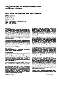
person. The followings are the features of the proposed architecture for an automated scene understanding: • Resistance to Attacks. We propose a distributed sensing so that the surveillance network can be operating even when a part of the network has been disabled through a malicious attack. • Tracking of Objects by Agents. The cameras distributed on the area of interest may not be sufficient to track all the objects at a given time. Therefore an approach based on agents is applied. • Automated Detection and Tracking. The OPUs detect objects present on the scene by means of background subtraction. • Merging of OPUs data before sending to SPU saves bandwidth as well as transmission energy. Furthermore, the SPU only has the relevant information because fusion process takes care of the redundancy on the data. • The architecture includes an object tracking system based on multi-agents paradigm. The tracking system include two agents models, region and object agents. III. PROPOSED ARCHITECTURE The proposed automated scene understanding architecture consists of two basic units, Object Processing Unit (OPU) and Scene Processing Unit (SPU). Figure 1 illustrates the relationship between them. Several OPUs form a cluster and one of them is designed as a cluster-head. A cluster-head is responsible for integrating all the information coming from the cluster members. Once the data has been merged, it is sent to the Scene Processing Unit for further processing. The OPUs are responsible for detecting moving objects present in the scene, and they share this information among them by means of wireless connections. Each cluster covers a specific area. Therefore, the information in a given cluster is highly correlated and useful as it gives us more information on the moving objects and positively impacts the false alarm ratio. There are several SPUs distributed throughout the network, providing several point of visualization by means of the Graphic User Interface. SPUs analyze the scene taking information, from all the cameras, from the clusters connected to it. Object classification into several predefined set is
OPU
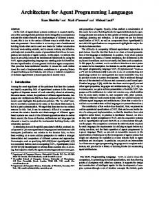
A. Object Processing Unit The Object Processing Unit (OPU) is in charge of sensing the area of interest and identifying moving objects in the scene. In order to perform its functions, an OPU will consist of four basic units: sensor, processing, transceiver and power unit. The OPU obtains the sensor data that could be image, seismic or acoustic, and then performs object detection. Once an object has been detected, the object model parameters are updated using the recent lectures of the sensor. When the sensors have some data to be reported to the SPU, a clusterhead is determined between all sensors in the cluster. The cluster-head is chosen based on the available energy of the nodes in a cluster. The OPU performs pre-processing on its own data, after which the data is sent to the cluster-head. A Cluster-head is in charge of merging this data, so that only the valuable information is sent to the SPU. This way bandwidth and energy is saved. Figure 2 shows a functional diagram of the OPU. Once the image has been obtained, object detection is performed. The object detection is performed by means of background subtraction. Background subtraction provides a foreground mask where only the moving objects are present. Foreground mask is passed to the cooperative-agent system, which is in charge of obtaining the object model parameters and tracking the present objects on the scene. Tracking system based on agent is discussed in the next section. The object model information along with the image of the object and model values are sent to the SPU.
OPU
OPU
OPU
OPU
performed into this unit. The information that flows through the network is only the object model information, i.e. no video is transmitted from the OPUs to SPU. This way the use of bandwidth is optimal. However, the architecture allows the possibility of viewing the actual video footage on the cameras. The dashed links in Figure 1 from the OPUs to the SPU represent this possibility. Each OPU has two action modes. The Default Mode processing will detect and track object and send only the object model information. The second mode is Video Mode in which the OPU sends compressed video to the SPU. The Graphic User Interface (GUI) reports the actions on the scene and provides a method to review video from the desired camera at a given time.
Scene Processing Unit (SPU)
OPU
Figure 1 Overall Proposed Architecture
Graphic user Interface (GUI)
Video Compression
SPU
Video Frame
Object Detection
Camera
Camera Action
Input from Neighboring OPUs
Region Agent
Data Fusion
SPU
Tracking
activities performed at the SPU. The tasks performed by the SPU are computationally complex, thus require high computation capabilities and memory as well as a database of threat patterns. OPU Compress Video
OPU Object Information
Object Classification
B. Scene Processing Unit Object model parameters and tracking information of these objects are sent to the Scene Processing Unit (SPU). Several OPU can detect the same object, therefore through the data fusion performed at the cluster-head, multiple instantiation of the same object are merged. Scene Processing Unit has a broader look at the scene under observation because it receives the information from all OPUs in the same area. Thus, the SPU can perform more accurate threat detection. Along with object model and tracking information, a segment of the image containing the detected object is received by the SPU. This segment is used by the classification and decomposition procedure. The object is classified as a person or vehicle. A person set contains a single person or a group of persons, while the vehicle set contains sedan, truck, delivery truck, 18 wheelers. If the detected object has been classified as a person, then decomposition procedure takes place. A person is decomposed into legs, arms and trunk. This decomposition is performed in order to determine if the person has a hazardous material in his arms, or strapped on his trunk, like a weapon, etc. This information is sent to the threat detection procedure. Based on that information the SPU decides what action will be proper, such as taking a closer look on the scene or an actual alarm detonation. Figure 3 shows a functional diagram of the
GUI
Report Generation
Object Decomposition
Figure 2 Basic function performed at OPU
1) Object Detection There are two well-known techniques for object detection in video stream: optical flow and background subtraction. Optical flow is capable of detecting object movement even when the background is also moving. However this technique is computationally complex. On the other hand, background subtraction is more suited to detecting movement or changes on the scene, yielding to a low complexity implementation. A fixed background is a requirement for this type of detection. Since we are considering only fixed cameras, background subtraction is a better candidate for our application. In addition, object detection must be performed in real time and using the least amount of memory because the resources of the OPU are limited. Background subtraction is done in several steps; first, the raw image is changed into a format that can be processed. Then a background model is built based on previous frames. Next, comparison between input frame and background model is performed. As a result, a foreground mask is built.
Video Decompression
Alarm Generation
Threat Identification
Figure 3 Functional diagram of SPU tasks
C. Graphic User Interface The Graphic User Interface (GUI) provides a daily report of action the area of interest. The report includes all information collected from OPUs on the particular object observed. But it also provides a tool to observe video from the cameras.
Sources
Sources Pre-processing
Object Refinement
SPU
Figure 4 Data fusion at the OPU
D. Model for Multi-sensor Data Fusion In a wireless sensor network, the information of interest is a global picture of what is happening inside the area of interest, which is more than an individual scan reading for each sensor. Therefore, a method to integrate all the data from each sensor must be provided. The model presented in [5] takes the data from multiple sensors and sorts them into the different task assigned to the system. Then, the data is transformed into frame to identify and classify object present on the scene (i.e., object refinement). The following step is situation refinement. Once each object has been identified, this stage tries to establish a relationship between objects on the scene. The last step is threat refinement where these relationships are drawn into the future to establish possible threats. Under this model, all the processing is done on a central control; the sensors are only responsible for sending their data. The burden of processing is allocated only at sink, and the distributed power of sensor network is wasted. To overcome this problem we divide the model as follows. The proposed system divides the Data Fusion Process Model so that the pre-processing and object refinement is performed at the OPU and the rest of the functions are realized at the SPU. This model not only takes advantage of the distributed nature of the sensors, but also increases parallelism and speed, because tasks can be done on each sensor at the same time. The functions to be performed on the OPU are depicted in figure 4, while the SPU functions are illustrated in Figure 5.
Situation Refinement
Threat Refinement
GUI
Database Management Systems Support Database
Fusion Database
Figure 5 SPU Data Fusion Flow
Blind Beamforming is used in our framework for fusion and detection. The Blind Beamforming enhances the signal by processing only the array data without much information about the array [6]. Blind beamforming with Least Mean Square algorithm uses a minimum mean square error criterion to determine the appropriate array weighting filters and is highly suitable for power aware wireless sensor networks [7-8]. This algorithm is employed in our approximation since it is power aware, it is easily adaptable to the propose data fusion model, and it does not require that all the signals are present at the same time.
B
B
C
A
C
C
D
D C
C
C
C
B. Cooperative Agents for detection and tracking The agent framework is well suited for application to scene understanding because it has multiple desirable characteristics [9], such as: provides mechanism for binding together a set of tasks related to a particular input, allows a clear specification of the interface between these sets and facilitates an event driven process control. Tracking people passing through an area of interest cannot be done by a single agent since the information on them is temporally and spatially distributed.
A
C
A. Operation of the system The area of interest is divided into sub-areas according to a range of view of cameras. Each sub-area contains a camera and possibly other minor sensors as acoustic sensors. The cameras perform object detection at all times. Each camera has a region agent (RA), which manages Object Agent creation. Object agent (OA) is responsible for tracking the object and sending the tracking information to the RA. Both agents reside on an OPU. The SPU takes the object and tracking information and performs object classification and decomposition. For highly restricted area, we assume a node-to-cluster ratio of 4 OPUs to 1 SPU, while for low security areas we consider a ratio of 20 OPUs to 1 SPU. The ratio is established depending on the processing time. In order to preserve real time operation, the SPU only can analyze a number of OPUs that has to be determined in terms of processing time. The system will initiate an alarm if any of the following situations occur • A threat is identified • OPUs are unable to keep contact with the SPU • OPUs are unable to communicate between them The latest could not be a real threat; however a defective communication could result in missing a real security problem.
C
IV. DESIGN, OPERATION AND SIMULATION OF THE SYSTEM
C
OPU
Cooperating agents that collect spatial and temporal information through the entire area solves the problem. Our approach to scene understanding incorporates agent under the following scheme. The area of interest is divided into several sub-areas in agreement with camera range view as illustrated in Figure 6. Each region corresponds to a sub-area where the camera has the best view. Each sub-area has assigned a camera and a Region Agent (RA). Video source is a fixed video camera with wide range of view. Region Agent receives the foreground mask after background subtraction process has been completed, along with the image. Then the image is segmented using the foreground mask. Each segment is sent to the Object Agents that have been already spawned by the Region Agent. If any Object Agent does not recognize a segment then a new agent is spawn to track that object. Object Agent is responsible for updating the object model consisting of velocity, acceleration and heading based on information subtracted from several frames. When an object approaches the border of the area monitored by the region agent, this agent must communicate with the proper agent to send all the information on the object to it. The Region Agent negotiates with its neighbor proper handoff of moving objects leaving its area.
Figure 6 Segmentation of the area of interest for two different camera dispositions
1) Region Agent Model Region Agent is responsible for monitoring its area as well as coordinating Object Agents already assigned to the detected objects. In order to perform its activities, a Region Agent consists of four modules: Communication Module, Object Agent Status Module, Object Agent Creation Module, and Decision Module. Figure 7 describes the agent model. Other Agents
Communication Module Region Agent Decision Module Object Agent Status Module
Object Agent Creation Module
Figure 7 Region Agent Architecture
In order to perform its activities, Region Agent must know the status of the Object Agent. When a new frame has arrived, Region Agent is responsible for segmenting the frame. Each
segment of the frame contains a detected object. The Region Agent marks all the object agents as NO_ID to indicate that none of the object agent has been able to identify the object present at the scene. When an object agent recognizes its object, it sends an acknowledgment message to the region agent then updates its status as ID_ACK. Decision module is in charge of generating all messages to the other agents. When a new frame arrives, the object agent status must be updated and messages are sent to object agents announcing the arriving of a new frame. Then, this module decides the order of transmission to the object agents. When a segment has not been identified for the object agents already created, a new object agent must be spawned. When an object is approaching the border of the area, communication with the proper Region Agent is engaged. The decision is based on the heading of the object. Communication module allows the Region Agent to exchange information with the other agents via a predefined set of messages. The type of messages and the content of the message are chosen by the decision module. The agents utilize a protocol based on the Knowledge Query Manipulation Language. Knowledge Query and Manipulation Language (KQML) [10] is based on speech act theory [11] and is a popular protocol that is being used widely for communication among agents [12-13]. All the necessary information for the correct interpretation of the message is included in the message itself.
Also, the Decision Module chooses when the update process must be performed. The Object Matching Module recognizes if the segment contains the assigned object. The decision is taken using the Mahalanobis distance. Mahalanobis distance is a technique to determine similarity between a set of values and an unknown sample [14]. 3) Ontology for the Multi-Agent System The simulation of the cooperative agents is done by ZEUS toolkit [15]. ZEUS toolkit provides tools for simulation and development of cooperative agents in form of Java classes’ package. ZEUS provides different default role modeling to implement the functionality inherent to multi-agent application. The first stage on ZEUS implementation is decided which role model suits the given implementation. The role model for this particular application is Shared Information Space. This model allows each agent to be publisher and subscriber simultaneously. The ontology is the shared understanding of the interest domain. Agents communicate between each other to cooperatively solve a designated problem. The communication is performed via messages. Each message contains parameters that posses a meaning in the problem domain. In order for the agents to understand these messages, they must share a common knowledge. The definition of the ontology is defined to be a set of facts. Table 1 present the set of fact defined for this application.
Others Agent
TABLE I FACT DEFINITION
Communication Module
Object Matching Module
Object Agent
Fact
Attributes
Image_Segment
Segment: image segment
Position_on_Fra me
Coordinates x, y: integer
Updated Module
Distance_to_Bor der Approaching_Bo rder
Tracking Database
Velocity
Distance: real Approach: Boolean Velocity: real Acceleration: real Heading: real
Decision Module
Figure 8 Object Agent Architecture.
Acceleration Heading
2) Object Agent Model An Object Agent is responsible for determining if its assigned objects appear on the scene. Also, it is responsible for updating the model and let the region agent know that a positive match was established. To execute its task, the object agent is composed by communication, object matching, update and decision module. This agent also contains a tracking database to store all the previous values of the velocity, acceleration and heading of the detected object. The object agent model is depicted in Figure 8. The Update module is responsible for updating the new object parameters in the tracking database. The Decision Module generates the message to communicate with the Region Agent. The Object Agent must inform when a positive match can be established.
Default
Meaning Segment containing the object to be match
False
Positive_id
ID: Boolean
False
Number_NegID
NO_ID: integer
0
NoSegment
NoSeg: Boolean
False
ObjectAgentID RegionAgentID
Name: string Name: string
Position coordinates of the upper left corner of the segment Distance of the object to the border Flag for object approaching border area Velocity of the detected object Acceleration of the detected object Heading of the detected object Positive match of the segment with the assigned object This value indicated that the object was not present on the current scene Indicated to object agent that there are no more segments to analyze Name of object agent Name of region agent
C. Object Detection Wronskian Change Detector Model (WCD) was implemented as our detection model [16]. WCD requires
0.9 0.8 0.7
0.5 0.4 Indoors Outdoors
0.2 0.1
0
0.05
0.1
0.15
0.2
0.25 0.3 Luminance
0.35
0.4
0.45
0.5
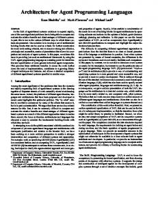
Figure 10 Detection Performance for Indoor and Outdoor Scene Under Difference Luminance Values
ACKNOWLEDGEMENTS The authors acknowledge the support of the U.S. Department of Energy (DoE), EETAPP program DE97ER12220, the Governor' s Information Technology Initiative, the DoE award DE-FGO2-04ER46136 and the Louisiana Board of Regents contract DOE/LEQSF (2004-07)-ULL, and the support of National Science Foundation NSF, INF 6-001-006. REFERENCES [1] [2] [3] [4]
[6] [7] [8] [9]
V. CONCLUSION A distributed scene understanding architecture has been presented. The architecture consists of several Object Processing Units distributed on the area under surveillance. Each OPU is attached to a camera. OPUs are responsible for detecting and tracking moving objects on the scene. Object detection is performed by background subtraction, while cooperative agents track detected objects. This information is sent to a Scene Processing Unit, which will classify and decomposed objects. Then, SPU determines if the scene contain a threat pattern and perform appropriate action. This architecture represents an effort to automate surveillance systems. Tasks are distributed in the network, so the SPU are not loaded of scenes that may not contain useful information.
0.6
0.3
[5]
b) a) Figure 9 Object Detection Results for an Indoor Scene, a) Image Containing Moving Object, b) Foreground Mask Obtained Using a 3 × 3 Window
Luminance Changes for Indoors and Outdoors Scene
1
Normalized Area
converting each pixel of an image into 9-dimensional vectors. The vector replaces the center pixel of a region of support. The component vector corresponds to the luminance values stored in each pixel of the image. A change in the region means that the luminance vectors are linearly independent. Our simulation accepts frame size is 640 ×480 pixels images. The original image is in RGB format that is converted to a luminance values. The camera generates 30 frames per second. However it is not really useful to subtract the background for each of these frames. Instead, our simulation took first and last frame each second. This interval reduces timing and power consumption. Background Subtraction algorithm requires vector generation of 9 elements, however the vector dimension could vary from 3 × 3 region to a 5 × 5 or even greater values. However, the detection improvement using higher windows values are not found to be extra useful. Therefore a fixed region of 3 × 3 is considered enough for our simulation. Figure 9 illustrates simulation results for background subtraction of an indoor image. Background subtraction algorithm must be robust against change of global illumination. In order to measure the performance of the Wronskian detector, images with different luminance average values were tested. The results are shown in Figure 10 for indoor and outdoor scenes. Since the system will be deployed on building and parking lots, a medium change of illumination can be assumed. Based on the results, Wronskian detector is sufficiently robust for our application. However, further improvement could be achieved by including an illumination compensation block before background subtraction.
[10] [11] [12] [13] [14] [15] [16]
A. R. Dick and M.J. Brooks, “Issues in Automated Visual Surveillance”, in Proc. of VIIth Digital Image Comp. Tech. and App., 10-12 Dec 2003, Sydney, pp. 195-204. R. T. Collins et al., “A System for Video Surveillance Monitoring”, Report No. CMU-R1-TR-00-12, Carnegie Mellon University, 1999. E. Shakshuki and Y. Wang, “Using Agent-Based Approach to Tracking Moving Objects”, Proc. 17th Int’l Conf. Adv. Information Networking and App. (AINA’03), 2003, pp. 578-581. P. Remagnino, A.I.Shihab and G. A. Jones. “Distributed Intelligence for a Multi-Agent Visual Surveillance”, The Journal of the Pattern Recognition Society Elsevier, 2004, Vol. 37, No. 4, pp. 675-689. J. Llinas and D. Hall, “An Introduction to Multi-sensor Data Fusion”, Proc. IEEE Int’l Symp. Circuits and Systems, ISCAS, vol. 6, MayJune 1998, pp. 537-540. J.C. Chen, K. Yao, and R.E. Hudson, “Source Localization and Bemforming”, IEEE Signal Processing Mag., Mar. 2002, pp. 30 – 39. W. Heinzelman et al., “Energy-Scalable Algorithms and Protocols for Wireless Microsensor Networks”, Proc. Int’l Conf Acoustics, Speech, and Signal Processing (ICASSP), June 2000, pp. 3722-3725. A. Wang and A. P. Chandrakasan, “Energy-efficient DSPs for Wireless Sensor Networks”, IEEE Signal Processing Magazine, vol. 19, no. 4 , July 2002, pp. 68-78. M. Dietl, J-S Gutmann, and B. Nebel, “Cooperative Sensing in Dynamic Environments”, Proc. Int’l Conf. Intelligent Robots and Systems”, Oct-Nov 2001, pp. 1706-1713. T. Finin, D. McKay, and R. Fritzon, “An Overview on KQML: A Knowledge Query and Manipulation Language”, University of Maryland CS Department, Technical Report, 1992. J. R. Searle, “Speech Acts: An Essay in the Philosophy of Language”, Cambridge University Press, 1970. M.N. Huhns and M.P. Singh, “Readings in Agents. San Francisco”, Morgan Kaufmann, CA, 1998. G. Weiss, “Multiagent System: a Modern Approach to Distributed Artificial Intelligence”, MIT Press, Cambridge, Mass., 1999. T. Kamei, “Face retrieval by an adaptive Mahalanobis distance using a confidence factor”, in Proc. Inter. Conf. on Image Processing. Sept 22-25 2002. Vol. 1, pp. I-153 - I-156. J.C. Collis, D.T. Ndumu, H.S. Nwana, L.C. Lee, “The ZEUS agent building toolkit”, BT Tech. Journal, Vol. 16, No.3, July 1998, pp. 6068. E. Durucan and T. Ebrahimi, “Change Detection and Background Extraction by Linear Algebra”, Proc. IEEE, vol. 89, no. 10, Oct. 2001, pp. 1368-1381.