In this paper, an architecture-independent software de- velopment approach for parallel processing systems is presented. This approach is based on the parallel ...
An Architecture-Independent Software Development Approach for Parallel Processing Systems* Stephen S. Yau, Doc-Hwan Baet and Jun Wang Department of Computer Science and Engineering Arizona State University Tempe, AZ 85287-5406,USA
'Information and Communication Engineering Department Korea Advanced Institute of Science and Technology Seoul, Korea
Abstract
etc do not address software development issues for parallel processing systems. Therefore, they are not suitable to solve more general applications.
In this paper, a n architecture-independent software development approach for parallel processing s y s t e m s i s presented. T h i s approach is based o n the parallel objectoriented and functional computation model PROOF and separates the architecture dependent issues f r o m software development. I t also facilitates software developm e n t for a n y parallel processing systems by relieving the programmers f r o m t h e consideration of processor topology and various parallelization aspects of the software. O u r approach allows t h e exploitation. of parallelism at both levels of granularity: object level and method level, ihereby making o u r approach effective f o r software development f o r various MIMD computers. Software developed using o u r approach will reflect the parallel structure of t h e problem. space which will make the software more understandable and modifiable. A framework consisting of object-oriented analysis, object-design, coding and t r a n s f o r m a t i o n phases i s presented f o r software development f o r parallel processing systems. An example is given t o illustrate this approach. keywords: architecture-independent software development, object-oriented paradigm, functional paradigm, parallel processing.
1
In this paper, we will present an architectureindependent approach for software development for parallel processing systems. It is based on the parallel object-oriented functional computation model (PROOF) 171 which incorporates the functional paradigm in the object-oriented paradigm. T h e objectoriented paradigm reflects the parallel object structure for the problem space and is suitable for representing inherently concurrent behavior, which makes the software more understandable and modifiable. The functional paradigm facilitates us t o exploit method level parallelism. The main advantage of this approach is that this methodology separates the architecture dependent issues from software development. Hence, the programmer does not need t o be concerned with the issues such as synchronization, parallelization or the network topology of parallel processing systems thereby making the software development independent of the architectures of parallel processing systems [SI. This approach will allow the exploitation of parallelism at both levels of granularity, coarse-grain at object level and fine-grain at method level, and is suitable for MIMD machines. An example will be given to illustrate our approach.
Introduction
In spite of vast increase in speed of various parallel processing systems, the potential for high performance computing systems for various applications such as command, control, communication, and intelligence systems, space exploration, weather prediction, and telecommunication systems, where there are many interacting components, shared resources, and computationally intensive tasks, cannot be realized without effective software development methods for such systems. Unfortunately such methods are far from being mature due to the complexity of concurrency and synchronization issues. The lack of such methods is a major obstacle for the effective use of parallel processing systems in various application areas. The existing software development approaches [l,2, 3, 41 for parallel processing systems focus on the exploitation of data parallelism in numerical computation and do not address design steps for developing parallel software. The well-known existing 0 0 A / O O D methods, such as CMT [5], Booch [ 6 ] ,
2
Our approach t o software development for parallel processing system is based on the computation model PROOF which incorporates the functional paradigm into the object-oriented paradigm. In PROOF, each object is an instance of a class, and can be either passive, active or pseudo-active. A passive object acts like a service agent. It waits passively until one of its methods is invoked by some other objects. An active object is active initially, and it may remain active throughout its execution, except for occasional suspensions for synchronization with other objects. A pseudo-active object is invoked by other objects, and in turn invokes methods of other objects. A body will be attached to each active and pseudo-active objects. Bodies of objects are functions whose roles are to invoke the methods and modify the states of the objects. A class is defined by its interface and definition. The class interface describes the signatures of the methods provided by the class. The class definition consists of the local data and the
'This research was supported by Rome Laboratory, U.S. Air Force Systems Command under contract numbers F30602-91-C. 0045 and F30602-93-0054.
0730-3157/95$04.000 1995 IEEE
Overall Framework
370
Authorized licensed use limited to: Korea Advanced Institute of Science and Technology. Downloaded on December 22, 2009 at 06:57 from IEEE Xplore. Restrictions apply.
the Petri-net model and many techniques are available to analyze Petri-net models. In the coding phase, the design of the software system is implemented in PROOF L. The coding in PROOF/L is straightforward and wil not be discussed in this paper. In the transformation phase, PROOF/L code is translated to a target code to be executed on a parallel processing system. The transformation of the program in PROOF/L into a target language involves the five major steps as shown in Figure 1: partitioning, frontend translation, grain size analysis, back-end translation and allocation. These steps can be divided into two groups, one for front-end translation and partitioning dealing with architecture independent issues, the other for grain size determination, back-end translation and allocation dealing with architecture dependent issues. In the partitioning step, the objects in the software system are partitioned into a set of clusters [9]. The objective of our partitioning approach is to iimprove the performance of the software by reducing communication cost among processors while maintaining the parallelization among objects. During this phase, we are only concerned with the object level parallelism. In the front-end translation, PROOF/L code is translated into IF1 (Intermediate Form l),a task precedence graph lo]. The purpose of this phase is to express the paralle ism in PROOF/L code explicitly in IF1 code. Then, grain size analysis is performed to determine the proper size of tasks to be executed on different processors in order to improve the performance of execution, and a modified IF1 code is generated. In the back-end itranslation, the modified IF1 code is translated into the t8argetcode. Architecture-dependent issues, such as communication overhead and processor load, are considered in the backend translation. Then, the target code is atllocated to processors. The details of the grain size ainalysis and transformation are given in [ll].
{
I
I
I 8
Back-End Translation
I : '1
,I
E3 Allocation
I
implmentation of methods of the class. The synchronization among the objects is achieved by attaching an optional precondition guard to the methods in a class. Each guard is a predicate. The object which invokes the method is suspended when the attached guard is evaluated to be False,and it is resumed when the guard predicate becomes True. The guard attached to a method is defined in a way that it only depends on the status of the local data, and does not depend on invocations of any other methods. Methods are defined as purely applicative functions or functional forms, i.e., high-order functions. Thus, it is easy to detect and exploit massive parallelism due t o referential transparency. Our framework consists of the following phases: object-oriented analysis, object design, coding in PROOF/L1, and transforming PROOF/L code to a target language of a parallel processing system. It is shown in Figure 1. In the object-oriented analysis phase, the system is represented by a set of objects and the interrelationship among the objects. In the object design phase, the objects identified in the object-oriented analysis phase are designed using the notations defined in PROOF. The class interface definitions and information about the object behavior are used to design the objects. The design of the objects has to be analyzed and verified for various liveness and safeness properties. For this purpose, we transform our design into Petri nets, which were used in our approach mainly because our design can be easily represented in
3
Object-Oriented Analysis
Our approach starts from the problem statements given in a natural language. We assume that the problem statements are complete in the functionalities of the problem without ambiguities. The approach given in [12] may be used to clarity the problem statements. The object-oriented analysis phase consists of the following steps.
1) Identify objects and classes.
2) Determine class interfaces. 3) Specify dependency and communication relationships among objects. 4) Identify active, passive and pseudo-active objects.
5) Identify the shared objects. 6) Specify the behavior of each of the objects.
7) Identify bottleneck objects, if any.
'A C++-based programming language with additional con-
8) Check the completeness and consistency.
structs required by PROOF/L.
371
Authorized licensed use limited to: Korea Advanced Institute of Science and Technology. Downloaded on December 22, 2009 at 06:57 from IEEE Xplore. Restrictions apply.
SEL(C;ml,. . . , m,): An object selects one of
In Step l ) ,objects are identified by analyzing the semantic contents of the requirement specifications. All physical and logical entities are recognized as object candidates. Each object corresponds to a real-world entity, such as sensors, control devices, data and actions. Objects having common behavior can be grouped together t o form classes. The nouns in the specification can be the candidates for the objects and the verbs for the operations [13]. The candidates for objects can also be detected from the data flow diagram[l4]. In Step 2), object class interfaces are determined. Because every object is considered as an instance of an object class, instead of defining objects directly, the object class t o which they belong must be defined. The interface of an object class consists of the signatures of the methods provided by the class. For each method, its signature consists of the input and output parameters and their types. In Step 3), the relationships among objects are specified using the object communication diagram, in which the objects are represented as rectangles, the links between the objects indicate the communication between objects, i.e., method invocations, the arrows on the links indicate the directions of invocations, the methods defined in an object as interface are written within the object with the method names beginning with a period, and the labels on the arrows show which methods are being invoked by an object. An example of the object communication diagram is shown in Figure 3. In Step 4), the objects are classified to active, passave or pseudo-actzve objects according to their invocation properties. They can be easily identified from the object-communication diagram. The active objects have outgoing arrows with optional incoming arrows for responses from other objects, the passive objects have only incoming arrows, and the pseudo-active have both incoming and outgoing arrows. In Step 5), the shared objects are identified. An object is a shared object if it has the local data which can be accessed by a number of objects. There are two kinds of shared objects: read-only and wrztable. A read-only shared object has the local data which cannot be modified by other objects. A wrztable shared object has the local data which can be modified by other objects. Read-only objects can be freely duplicated as many times as desired. However, wrztable objects should not be duplicated easily because maintaining the consistency of the data will cause additional overhead. Shared wrztable objects may be bottleneck objects as they may have t o be executed sequentially t o maintain the consistency of the states of the objects. In Step 6), to specify the behavior of an object, we use the notations similar to those in [15]:
the methods for execution from the methods ml, ma,.. . . , m , based on a condition C. It behaves similar to the CASE statement in ordinary programming languages.
ONE - OF(WAIT(m1,O j ) ,. . . , WAIT(m,, Ok)): An object permits only one of its methods t o be invoked by other objects among the set of methods ml , 1122, . . ., m, defined in the object. It is typically used t o describe the behavior of shared writable objects, which can serialize method invocations from other objects that arrive simultaneously. ONE-OF will always be associated with a WAIT construct in a shared writable object because the object 0 will have to wait for other objects t o invoke its methods. In Step 7), the bottleneck objects, which may degrade the performance of the software system to be developed, are usually shared writable objects and identified from the description of the object behavior in the above step. If such an object is found, then redo or refine the objectoriented analysis to reduce the bottleneck if possible t o prevent these objects from limiting parallelism. This step may increase the number of objects in the software system. Repeat Steps 2) to 6 ) until the object-oriented analysis is found satisfactory. In Step 8), the result of the object-oriented analysis is verified with the given user requirements from which the possible threads of controls are identified, and each of them is examined using the behavior of the objects specified in Step 6). The verification can be done as follows [16]: First, the results of the object-oriented analysis are transformed into the specfication using a formal specfication language, which is converted into an information tree. Then, the completeness and consistency between the results of the object-oriented analysis and the user requirements can be verified by comparing the information tree with the user requirements.
4
Object Design
In our approach, the object design is specified using the notations defined in PROOF[7]. The class interface, definition, and information about the object behavior are used t o design the objects. Our approach t o object design involves three steps: 1) Establish the class hierarchy.
2) Design the class composition and the methods in each object.
3) Design the bodies of the active and pseudo-active objects.
SEQ(m1 , m2,. . . , m,): The methods ml , m2, . . ., m, are executed sequentially in the order ml, m2, . . ., m,.
In Step l ) ,a set of operations and/or attributes that are common to more than one class can be abstracted and implemented in a common class called the superclass. The subclasses then have only the specialized features. Many human decisions are involved in building the class hierarchy. However, the similar method/data pattens presented in different class interfaces can provide hints for the developers to effectively derive superclasses/subclasses relations. In some cases, a superclass
CON(ml , m 2 , .. . , m,): T h e methods ml , m2, . . ,, m, are executed concurrently. WAIT(m,0 ) :An object is waiting for the invocation of its method m by another object 0 to proceed with its execution. 372
Authorized licensed use limited to: Korea Advanced Institute of Science and Technology. Downloaded on December 22, 2009 at 06:57 from IEEE Xplore. Restrictions apply.
can be extracted from a single subclass and put in the class library if needed. Establishing a class hierarchy in the form of superclasses and subclnsses increases the reusability in the application. Class hierarchy also enhances the modularity and the extensibility of the software system. In Step 2), the composition of the local data and the methods for each object class are designed. The composition defines the internal data structure of the class. Various constructors, such as list and Cartesian product, are provided. A typical functional style is adopted in the method definition. In the method design, the internal state of the object to which the method belongs is included as both the input and output parameters so that side-effects can be avoided. A method of an object consists of an optional guard and an expressaon. The synchronization among concurrent objects is achieved by the guards attached to the methods. The guard attached to a method is defined in a way that it only depends on the status of the local data, but does not depend on the definition of other methods. Therefore, the guards are directly inheritable with the methods. Due to the referential transparency of applicative functions, fine-grain parallelism can be exploited. Selection of algorithm and data structure is an important part of the method design. The selection of algorithms to accomplish a specific task should be based on certain criteria which satisfy the required constraints such as accuracy, timing requirements, use of common utili ties across the design, reuse of previously developed software, computational complexity, flexibility, ease of implementation, understandability, etc. In Step 3), a body is associated with each active and pseudo-active object. There is no body associated with a passive object as it does not invoke any methods. The role of a body is to invoke a method and to modify the state of the objects represented by their local data. The body in each object is expressed in the form e l / / e a f / . . . / l e k where each e; is an expression representing method invocations and expressions separated by / f are evaluated simultaneously. // is a parallel construct indicating parallel execution. ei can be recursively defined and can be diverse. Thus, the evaluation process may be infinite. In e i , methods of objects can be invoked, and the states of objects may be modified. The modification of an object is expressed by the receptzon construct which has the form R[lOl]e,where 0 called a reczpient object is an object name and e is an expression with applications of purely applicative functions. The reception construct can occur only in the bodies of active and pseudo-active objects. The reception construct indicates that the object 0 will receive the value returned by evaluating the expression e.
5
ber of links and number of processors, are used to perform various analysis. We have developed the frontend translator from PROOF/L to IF1 and two back-end translators from IF1 to nCube C and KSR C, respectively.
6
An Example
In this section, we use an example of a warehouse management system to illustrate our approach. A simplified version of the requirements specification of the warehouse management system is given as folllows: The warehouse management system interacts with manufacturers and customers, and manages the warehouse. Manufacturers generate goods upon request from the warehouse manager, and send them t o the warehouse manager. The warehouse manager store the goods in the warehouse racks, and retrieves them t o the customers upon customer’s request. The capacity of this warehouse is fixed. Reports of transaction information are generated periodically.
6.1 Object-Oriented Analysis 1) From the requirements specification, the following objects are identified: manager, producer, consumer, reporter and rack. 2) As an example, the interface of rack is shown as follows: c l a s s rack; method put :: rack -> itemtype -> rack: method g e t : : rack -> rack X itemtype; end c l a s s
The method put has rack and itemtype as its input parameters and rack as its output parameter. The method get has rack as its input parameter and rack and itemtype as its output parameters. 3) Dependency and communication relationships among objects are identified and described in an object communication diagram shown in Figure 3 (a). 4) consumer is an active object, manager and producer are pseudo-active objects, and rack and repori!erare passive objects. 5) rack and reporter are shared objects. For example, the methods defined in rack - put and get - update the local data in rack, so rack is a writable shared object. 6) The behavior of each object is specified. For example, rack has two methods put and g e t , which are invoked by follows: manager. The behavior of rack is specified O N E O F (WAIT(put, manager),WAIT( get, manager)). 7) In manager, two control threads can be found: one is initiated by manager to receive items from producer and the other by consumer to retrieve items. Thu!j, manager can be split into two objects as shown in Figure 3 (b). 8) Control threads are verified by starting from the active objects, such as consumer, and tracing the methods invocations based on the object behavior.
Transformation
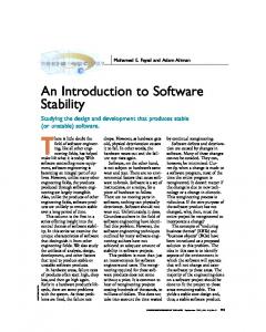
Tbe transformation of PROOF/L code to a target code involves two steps as shown in Figure 2: The first step is called front-end transformation, which makes the implicit parallelism present in PROOF/L code explicit. This step is a semantics-oriented transformation, and architecture dependent issues are not involved. The second step is called the back-end transformation. This step is performance-oriented, and architecture dependent parameters, such as communication types, num-
6.2 Object Design 1) In this example, each object is an instance of a different class, except p-manager c-manager. We can define a class called manager-class having the common method transaction-in, that can be inherited to its subclasses, p-manager and c-manager. 373
Authorized licensed use limited to: Korea Advanced Institute of Science and Technology. Downloaded on December 22, 2009 at 06:57 from IEEE Xplore. Restrictions apply.
-
PROOFL
First Phase
IF1
z-
Target Code
Second Phase
z-
I
I
Scheme or Detecting $atterns
Tgnffion
Figure 2: Major steps in transformation of PROOF/L code t o a target code. [Beta[tail,decl buf, head(buf .r)] end class
in the above buf is an instance of rack, and Beta, appendiight, tail, head, inc and dec are defined as follows: f i , fz, ..., f n 1 [ti,22, . . - )ZC,] E [ f 1 ( ~ 1 ) , f Z ( 4 , . . .>f n ( x n )
Beta [
31
0
deliver-to-consumer
reporter .transaction-in .disp1ay
deliver-to-manager
appendiight z y = y o [x]
0
tail [ e l , e 2 . . .e,] E [ez, e3 . . .e,]
0
head [el, e2 inc n E n
t
E el
+ 1;dec n E n - 1.
3) An important aspect of the design here is indicating the modification of the objects. For this we attach R a t the method put since this method modified the p-manager. Thus, R[lrackI] put is substituted in place of put. This modification of body will be implemented at the coding stage. The design of other constructs is similar and will not be discussed here. The perspective version of pseudo code for the nCube parallel machine for the get method generated through the front-end and back-end transformation is shown as follows:
t
1
1
. . .e,]
(b)
Figure 3: (a) An object communication diagram for the warehouse management system, and (b) modified object manager.
void rack-get(rack *buf, rack *return-rack, itemtype *return-itemtype) {
1
2 In the following we only give the definition of the c ass rack shown as an example:
/* s e l f - l o o p f o r passing the guard */ while (buf->count 0) expression
parallel dispatch the tasks */ dispatch ( tail(buf->r) -> return-rack->r ) ; dispatch ( dec(buf->count) -> return-rack->count ) ; dispatch ( head(buf->r) -> *return-itemtype ) ; wait for results;
1 374
Authorized licensed use limited to: Korea Advanced Institute of Science and Technology. Downloaded on December 22, 2009 at 06:57 from IEEE Xplore. Restrictions apply.
J . Rumbaugh, M. Blaha, W. Premerlani, F. Eddy and W.Lorenson, Objecl-Orienied Modeling and Design, Prentice Hall, 1991.
Garbage collection for any unreferenced objects will be performed along the execution.
7 Discussion
G. Booch, Object-Oriented Design wii!h Applica-
In this paper, we have presented an architecture-
iions, Benjamin Cummings, 1991.
independent approach to software development for pardlel processing systems based on the computation model PROOF, which incorporates the functional paradigm into the object-oriented paradigm. The software will be developed in PROOF/L, which is a C++based langauge with addtional constructs required by PROOF. Then, PROQF/L code is translated to a target language of the given parallel processing system for execution. Our approach relieves the programmers from the consideration of processor topology and various parallelization aspects of the software development, and facilitates the exploitation of parallelism at both levels of granularity - object level and method level. The software developed using our approach will be easy to understand and modify since the structure of the software reflects the structure of the problem. Functional paradigm used in the method design also permit the expression of massive and implicit parallelism. We have developed the front-end and back-end translators for the nCube and KSR-1 parallel processing systems and a number of examples have been experimented. We are incorporating the optimization teehniques, such as function call in-lining, useless expression removal and common subexpression extraction, as well as are implementing the grain size determination algorithrn in order to improve the performance of the target codes. CASE tools need t o be developed to aid the software developer in various stages in our approach, such as checking the consistency in the decomposition stage, design process and transformation of the design into the corresponding Petri-Net models.
S. S. Yau, X. Jia, and D.-H. Bae, “PROOF: A Parallel Object-Oriented Functional Computation Model,” Jour. Parallel and Distributed Computing, Vol. 12, No.3, July 1991, pp. 202-212.
S. S. Yau, D.-H. Bae, and M. Chidambaram, “Object-Oriented Development of Architecture Transparent Software for Distributed Parallel Systems,” Computer Communications, Vol.. 16, No. 5, 1993, pp. 317--327.
S. S. Yau, D.-H. Bae, and Gilda Pour, “A Partitioning Approach for Object-Oriented Software Development for Parallel Processing Systems,” Proc. 16th Annual 4nt’l Computer Software & Applications Conf. (COMPSAC92), 1992, pp. ;!51-256. Livermore National Laboratory, An Intermediate Form Language IF1 Reference Manual, 1985.
S. S. Yau, D.-H. Bae, M. Chidambaram, G. Pour, V. R. Satish, W.-K. Sung, and I