Journal of Physics: Conference Series
PAPER • OPEN ACCESS
An ASI Suppression Scheme Based on Array Synthesis To cite this article: Jinhua Zhu et al 2017 J. Phys.: Conf. Ser. 910 012032
View the article online for updates and enhancements.
This content was downloaded from IP address 191.96.251.191 on 02/11/2017 at 01:19
CTCE2017 IOP Conf. Series: Journal of Physics: Conf. Series 1234567890 910 (2017) 012032
IOP Publishing doi:10.1088/1742-6596/910/1/012032
An ASI Suppression Scheme Based on Array Synthesis Jinhua Zhu, Peixi Liu and Wu Luo The State Key Laboratory of Advanced Optical Communication Systems and Networks, Peking University, Beijing, China Email:
[email protected],
[email protected],
[email protected] Abstract. An adjacent satellite interference (ASI) suppression scheme based on transmitting antennas array synthesis is proposed in this paper. The scheme ensures the ASI under the upper bound specified by international regulations, and simultaneously maximize the main-axis radiated power. Specifically, the interference suppression problem is converted into a uniform linear array (ULA) synthesis problem, and then solved by two algorithms. Numerical results are presented to illustrate the performance of the scheme.
1. Introduction Due to the wide beam, the very small aperture terminal (VSAT) and the ultra small aperture terminal (USAT) usually lead to strong ASI. It may cause serious deterioration to the performance of the adjacent satellite system. Various international regulations have been issued to restrict the ASI. ITU-R S.728-1 [1] and FCC 47 C.F.R.§25.222 [2] specified the upper bound of the off-axis effective isotropic radiated power (EIRP) spectrum density. And ITU-R S.738 [3] presented a criterion for deciding whether coordination is needed between adjacent satellite systems. If the noise temperature increment caused by the ASI is greater than the specified threshold (6%), then interference coordination is necessary. By comparing the regulations, it can be deduced that ITU-R S.728-1 has a strict limit on USAT and can be an alternative for the noise temperature increment criterion [4]. In ITU-R S.728-1, it is recommended that the off-axis EIRP spectrum density of the VSAT earth stations operating with geosynchronous orbit (GEO) satellites in the 14GHz frequency band should not exceed the following value [1] in the systems where the satellite spacing is near 2 . We need to keep the off-axis EIRP spectrum density no greater than IT U and, at the same time, maximize the main-axis radiated power to improve the communication quality. IT U ( ) [ d B W / 4 0 k H z ] 2 5 2 5 lo g 6 1 8 2 5 lo g 14
2 7 9 .2 48
7 9 .2 48 180
(1)
2. Problem Description For a given envelope shape of the antenna beam pattern, the main-axis radiated power cannot increase any more, as long as the ASI in a certain off-axis angle reaches the specified upper bound. In order to avoid the bottleneck effect caused by the ASI in a certain direction, the envelope of the antenna beam pattern is desired to match the IT U curve. We use an antenna array to achieve this, because the envelope of its beam pattern can be easily controlled by adjusting the element weights. The structure of an array antenna is shown as Figure. 1.
Content from this work may be used under the terms of the Creative Commons Attribution 3.0 licence. Any further distribution of this work must maintain attribution to the author(s) and the title of the work, journal citation and DOI. Published under licence by IOP Publishing Ltd 1
CTCE2017 IOP Conf. Series: Journal of Physics: Conf. Series 1234567890 910 (2017) 012032
IOP Publishing doi:10.1088/1742-6596/910/1/012032
θ
φ
... w
w
0
Equatorial plane
w
1
N-1
Source Figure 1 Structure of Array Antenna Define the weight vector w w0
w1
w N 1
...
H
(2)
and the steering vector [5] j 0 ,
a , e
e
j 1 ,
...
e
j N 1 ,
T
where , is the phase difference between the signals on element 0 and element beam pattern of the array can be expressed as n
G ( , ) w
H
a , .
(3)
,
n
. Then the
(4)
Uniform rectangular array (URA) is a widely used type of antenna. For URA, , where is the wave number and is the element spacing. Hence, the beam pattern of an M N array is given by M 1 N 1
G ( , )
wmne
jk d s in m s in n c o s
.
(5)
m 0 n0
In the equatorial plane (
0
), (5) can be simplified to G ( )
N 1 M 1
n0
wmn e
m 0
jn k d s in
.
(6)
By Comparing (6) with the beam pattern of a ULA G
N 1
n0
we obtain the following formula
2
wne
jn k d s in
,
(7)
CTCE2017 IOP Conf. Series: Journal of Physics: Conf. Series 1234567890 910 (2017) 012032
IOP Publishing doi:10.1088/1742-6596/910/1/012032
M 1
wn
(8)
wmn .
m 0
Therefore, the equatorial beam pattern of a URA is equivalent to the pattern of a ULA with the element weights given by (8). Based on this, the original problem can be converted into a ULA synthesis problem. In order to optimize the equatorial beam pattern of an M N URA, we just need to perform array synthesis on a N -element ULA, and distribute its n -th element weight to the n -th column of the rectangular array, as shown in Figure. 2. The method of distribution will influence the beam pattern in the meridian plane; however, that is not concerned in this problem. Uniform Rectangular Array
... ...
...
... ... ...
Distribute
Distribute
... Uniform Linear Array
Figure 2 Weight Distribution 3. Array Synthesis In this part, we discuss the array synthesis algorithms for the ULA. 3.1 Virtual Interference Algorithm To show the idea of the proposed virtual interference algorithm, we consider the antenna array operating on receiving mode. The weights that maximize the output signal-to-interference-plus-noise ratio (SINR) often form nullings in the incident directions of the interferences. Moreover, an interference with larger power usually leads to a deeper nulling. Inspired by this, we place a large number of virtual interferences in the sidelobe region. By adjusting the power of the interferences, the envelope of the beam pattern can be arbitrarily controlled [6]. Assume that one desired signal and M uncorrelated virtual interferences are incident on the N -element array from angles
0 , 1 , 2 , ... M
white Gaussian noise with variance
2
. The power of the interferences are
P1 , P2 , ..., PM
. Additive
is introduced by each element. The upper bound of the
IT U
sidelobe is set as , where determines the sidelobe height. If is too small, the sidelobe height constraint will be impossible to satisfy; if is too big, the main-axis radiated power will not be sufficiently large. In practice, the value of is usually decided by trial. The steps of the virtual interference algorithm are described as follows: 1) Initialize P to ; 2) According to the maximum SINR criterion, fix the gain in angle and minimize the output power of the interferences and the noise. The weight vector is expressed as [7][8] 2
m
0
3
CTCE2017 IOP Conf. Series: Journal of Physics: Conf. Series 1234567890 910 (2017) 012032
IOP Publishing doi:10.1088/1742-6596/910/1/012032
R 1 a 0
w a
0 R 1 a 0
H
(9)
,
where M
R
Pm a m a H m 2 I .
(10)
m 1
3) If the beam pattern does not exceed the specified upper bound Otherwise, adjust the power of the virtual interferences to [9][10]
i w Pm
i 1
Pm
where is the speed factor and 4) Go to step 2).
H
IT U
a m a H m w
IT U m
, the algorithm terminates.
(11)
,
is the sidelobe height factor;
3.2 LP Algorithm In the LP algorithm, we first compute the auto-correlation sequence of the element weights, and then obtain the weights by performing spectrum factorization. Let x be the auto-correlation sequence of w [11], then x is given by m
n
m
N 1 m
xm
(12)
wn wnm .
n0
For a ULA, the beam pattern can be expressed as G
w
H
N 1
wne
a a
2
N 2
wn wn 2
n0 N 3 n0
w
s in
jn k d
n0 N 1
H
n0
N 1
wne
jn k d s in
n0
w n w n 1 c o s k d s in
(13)
w n w n 2 c o s 2 k d s in ... N 1
x 0 2 x m c o s m k d s in . m 1
Our aim is to limit the height of the sidelobe and maximize the main-axis gain. N 1
m a x x0 2 xm m 1 N 1
s .t. x 0 2 x m c o s m k d s in IT U ,
s id e ,
(14)
m 1
where is the sidelobe region. Equation (14) is a LP problem of x . It can be solved quite efficiently by MATLAB functions or toolboxes (e.g. linprog). m
s id e
4
CTCE2017 IOP Conf. Series: Journal of Physics: Conf. Series 1234567890 910 (2017) 012032
IOP Publishing doi:10.1088/1742-6596/910/1/012032
However, the auto-correlation sequence x cannot be directly applied to the array, and the m
weight sequence w has to be computed. Here we use a technique called spectrum factorization. Its steps are described as follows [12]: 1) Interpolation n
x 0 , x1 , ..., x N 1 , 0 , ..., 0 , x N 1 , ..., x1 ,
(15)
2 R 1
where R is 5 to 10 times larger than N ; 2) Perform fast fourier transformation (FFT), logarithmization and inverse FFT (IFFT) on (15) and form the vector y
y IF F T ln F F T x .
Due to the symmetry of (15),
y
can be expressed as y
3) Let the vector
v
(16)
y 0 , y1 , ..., y R , y R , ..., y1 .
(17)
be v
4) Perform FFT, exponent and IFFT on
v
y0
(18)
/ 2 , y 1 , ..., y R .
and form the weight vector
w IF F T e x p F F T v .
(19)
From the derivation of the array synthesis algorithms, it can be deduced that the LP algorithm can only be applied to ULA or URA, and the virtual interference algorithm is suitable for arbitrary arrays. According to the commutation relation between the transmitting and receiving antennas, the scheme discussed above can also be applied to the array synthesis problem of the receiving antenna. 4. Numerical Results
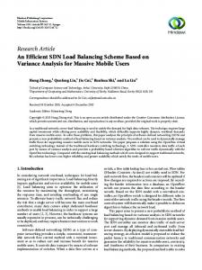
Figure 3 Synthesis Result
5
CTCE2017 IOP Conf. Series: Journal of Physics: Conf. Series 1234567890 910 (2017) 012032
IOP Publishing doi:10.1088/1742-6596/910/1/012032
The beam pattern of a 6 0 6 0 rectangular array computed by the virtual interference algorithm ( 0 .2 7 8 , 0 .0 0 0 5 ) and the LP algorithm ( R 6 0 0 0 ) are shown as Figure. 3. The element spacing is half-wavelength. We can see that the envelope of the beam pattern matches the IT U curve, and the synthesis results of the two algorithms are similar. When the sidelobe height factor is set as a proper value, the time cost of the two algorithms are close to each other. In the example above, it takes 2.49s and 2.83s respectively for two algorithms to solve the array synthesis problem (Test environment: Intel(R) Core(TM) i5-5200U CPU 2.20GHz 2, 8GB RAM, MATLAB 2016b). The virtual interference algorithm is even a little bit faster. However, as we mentioned before, the factor in this algorithm needs to be determined by trial. This will lead to some inconvenience. 5. Conclusion An ASI suppression scheme for transmitting antennas is proposed in this paper. In order to suppress the ASI and maximize the main-axis radiated power, we need to solve a ULA synthesis problem, and distribute the weights of the ULA to the elements of the original array. Two array synthesis algorithms are studied, and numerical results show that the synthesis result and the time cost of the algorithms are similar, but the LP algorithm is more convenient. 6. References [1] International Telecommunication Union, “ITU-R Recommendation S.728-1, Maximum Permissible Level of Off-Axis EIRP Spectrum density from Very Small Aperture Terminals (VSATs),” 1995. [2] Federal Communications Commission, “FCC 47 CFR Ch.1 25.222, Blanket Licensing for provisions for Earth Stations on Vessels (ESVs) receiving in the 10.95-11.2 GHz(Space-to-Earth), 11.45-11.7GHz((Space-to-Earth)), 11.7-12.2GHz((Space-to-Earth)) frequency bands, operating with Geostationary Satellites in the Fixed-Satellite Service,” 2010. [3] International Telecommunication Union, “ITU-R Recommendation S.738, Procedure for determining if coordination is required between geostationary-satellite networks sharing the same frequency bands,” 1992. [4] Y Ma, J Zhu, W Luo, “ASI regulations comparison for GSO satellite communication system at Ku-band,” International Conference on Control, pp. 171-175, 2015. [5] SN Shahab, AR Azinun, NH Noordin, SS Balasim, “Assessment of MVDR Adaptive Beamforming Algorithm in Uniform Linear Arrays, Uniform Rectangular Arrays and Uniform Circular Arrays Configurations,” APRN Journal of Engineering and Applied Sciences, vol. 11, pp. 3911-1917, 2016. [6] Y Ding, C Liu, Y Zhao, H, Chen, “Robust Wideband Beamforming Algorithm to Suppress Multipath Interference,” Journal of Signal Processing, vol. 30, pp. 1104-1111, 2014. [7] SR Tuladhar, JR Buck, “Unit circle MVDR beamformer,” IEEE International Conference on Acoustics, Speech and Signal Processing, pp.2484-2488, 2015. [8] L Zhang, W Liu, B Peng, “Generalized eigenvector problem for Hermitian Toeplitz matrices and its application to beamforming,” Signal Programming, vol. 92, pp. 374-380, 2012. [9] X Liu, C Liu, G Liao, “Improved pattern synthesis method with linearly constraint minimum variance criterion,” IEEE International Conference on Wireless Communication, pp. 63-66, 2010. [10] C Liu. “Robust Beamforming and DOA Estimation,” Fourier Transform Applications, Dr Salih Salih, ISBN: 978-953-51-0518-3, InTech, 2012. [11] K Huang, YC Eldar, ND Sidiropoulos, “Phase Retrieval from 1D Fourier Measurements: Convexity, Uniqueness, and Algorithms,” IEEE Transactions on Signal Processing, vol. 64, pp. 6105-6117, 2016. [12] J Jezek, M Hromcik, M Sebek, “New algorithm for spectral factorization and its practical application,” Control Conference, pp. 3104-3109, 2001.
6