An Automated Verification Process Based on Scan Techniques Gustavo R. Alves DEE / ISEP Rua S. Tome 4200 Porto – Portugal
[email protected]
Marcelo S. Lubaszewski
Margrit Reni Krug
PPGC / UFRGS Av. Bento Gonçalves, 9500 CEP 91501-970 Porto Alegre – Brasil
[email protected] [email protected]
Abstract Matching the results achieved during circuit simulation with those extracted from circuit functioning is a common verification process. A large number of current verification techniques use the input / output vectors produced during functional simulation as the test vectors applied / compared against the circuit responses. Techniques that are more complete include extracting the values of internal sequential nodes and comparing these using internal scans. This paper describes a solution for verifying digital designs implemented in currently commercial available CPLDs. All internal flip-flops are included in a scan-chain accessible through the BST infrastructure (using a user-defined optional instruction), while the BS cells are used to apply the input test vectors and capture the circuit responses. These BS cells can either belong to the device-under-test or to other devices, the first controlled through the optional INTEST instruction and the second controlled through the mandatory EXTEST instruction. To speed up the verification process, the test program is automatically generated from information that encompasses the design & development phase.
1. Introduction Comparing the results obtained from the simulation phase with those extracted from real circuit behaviour is a traditional method of circuit verification, sometimes referred as functional test. While this method can be extended to comparing the values of internal flip-flops (FFs) [1, 2], the need for expensive test equipment prevents such an approach for small research groups with limited budgets. The presence of a Boundary Scan Test (BST) infrastructure in current commercial available Complex Programmable Logic Devices (CPLDs) is a possible solution for implementing a similar approach using two optional instructions described in the standard [3] and a chip-level controller previously developed for debugging & testing board-level applications [4, 5, 6, 7]. The INTEST instruction allows the application of a test vector to input pins and the capture of a response vectors
José M. Martins Ferreira DEEC / FEUP Rua dos Bragas 4000 Porto – Portugal
[email protected]
in output pins, while a simple user-defined optional instruction called ‘INTSCAN’ allows capturing the values present in internal sequential nodes. The test controller named PROcessor for DEbug Purposes (PRODEP) is responsible for controlling all test operations, namely for shifting in / out the test vectors through the CPLD Test Access Port (TAP). The test program executed by PRODEP is automatically generated from information that encompasses the design & development phase. Key points of our solution include: a low-cost approach dispensing the use of complex test equipment, re-use of simulation results, re-use of a board-level BS controller, and use of in-house software relatively simple to develop (the automatic test program generation tool). Additional contributions include the identification of flaws in the optional INTEST instruction (defined in the IEEE 1149.1 standard), and in the BSDL file, in what refers to access to internal scan chains, through the BST infrastructure. This paper is organised as follows: after this introduction, section 2 describes the test program generation process, namely the data flow, and the input / output information. Some details of the internal data structure are provided to highlight that most of this process is actually devoted to ordering information extracted from existing files. The considerations on the INTEST instruction and on the BSDL file are included in this section. Section 3 describes how PRODEP is connected to the circuit under verification and how the test program is executed. Section 4 is devoted to the error1 detection / location / diagnosis process. Finally, section 5 concludes this paper.
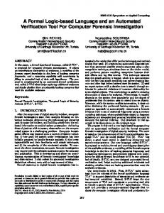
2. Test program generation The data flow in the test program generation process is illustrated in figure 1 that also serves as a basis for the following description. Most of the input information required by the automatic test program generation (ATPG) tool is provided from earlier stages of the design & development process. The tool requires five inputs: 1
An error is understood here as a mismatch between a captured value and an expected value in either a pin or an internal FF.
• a file containing the simulation results (both the input stimulus and the circuit values for both the output pins and the internal FFs); • the device’s BSDL file (provided by the CPLD manufacturer or which may be automatically generated using commercially available software); • a file describing the internal scan chain ordering; • a file containing the user options; • the structural test vectors (optional). The first file, provided by the simulation tool, contains a complete description of all the simulation channels used, i.e. the input / output / bi-directional pins and the internal flip-flops (which may be all or just a fraction of the total number of flip-flops existing in the circuit). Interpreting this file is sometimes a major problem, as currently there isn’t a widely used public or de facto standard for the format of the simulation results file. The one generated by the MaxPlusII development system2 comes in a tabular form, in ASCII, where columns correspond to circuit signals (inputs / outputs / internal nodes) and rows correspond to time moments. The cell corresponding to a row (time) – column (signal) intersection contains the signal value of a particular circuit location in a particular moment. Simulation files in this format (with minor variations) are quite common to find, and in fact, they represent a kind of files that are easier to process in order to extract the needed information. In our case, we developed a simple C program that performs this operation, providing the information needed to the ATPG tool in a pre-defined format, later presented in this paper. The BSDL file maps the device’s input / output / bidirectional pins to the corresponding BS cells. Our approach includes two options: the vectors may either be applied / captured through the BS cells of device, using the optional INTEST instruction, or through the BS cells of other devices, using the EXTEST instruction. The first option has some drawbacks: • it relies on a optional instruction that sometimes is not supported by commercial available CPLDs; • the standard defines several ways in which singlestep operation may be achieved. This presents some problems to the ATPG tool, namely because there isn’t a well-documented form of indicating which option is actually implemented in a certain device. • INTEST places the BS cells associated with the device input pins in the control mode and those associated with the device output pins in the capture mode. While this is what is intended, when the optional instruction used for accessing the internal scan chain is loaded in the instruction register, the BS cells will be placed in the transparent mode, thus disrupting the permanent application of a stable input test vector. If not properly considered, this switch may cause potential hazards to the circuit-under-test. 2
Development system used for Atera’s CPLDs [8].
Figure 1: Data flow of the ATPG process The second option requires additional components solely used for providing the necessary BS cells acting as test channels. The BSDL file contains also the opcodes of the SAMPLE/PRELOAD, INTEST and ‘INTSCAN’ instructions. Currently there is a serious omission in the contents of this file, namely the standard does not define a way of presenting the ordering of an internal scan chain accessible through the BST infrastructure. A different file generated by another in-house tool provides this information. The user configuration file contains additional information for the way the test program will be executed, namely some options closely associated with the resources available in our board-level BS controller. The last file is supposed to be provided in Serial Vector Format (SVF), to enable a structural test of the circuit implemented in the CPLD. The SVF program is actually translated to our format and embedded in the final test program. The possibility to run a structural test plus a functional test thus expands the diagnosis capabilities. The ATPG tool processes the input information and produces two output files corresponding to the programs to be executed by each one of the two controllers that are embedded in PRODEP. One controller (CLT) is able to control two BS chains and the other (CLF) is able to control one system clock and several general-purpose input / output pins The operations of both controllers are synchronised at machine level (through a common input clock) and at program level (through dedicated instructions). Figures 2 and 3 provide an idea on how the internal data structure is first formed, after reading the several input files, while figure 4 provides an excerpt of the test vectors to be applied / compared through shift operations. These vectors are extracted from the file with the simulation results, where the individual values (bits) are placed in the right order using the information provided by the internal data structure. Notice that the simulation channels and the BS cells (or the internal FFs) do not necessarily share the same order.
Nodes ________________ id: clock1 type: input boundary_cell: 37, BC_4 ________________ id: sel_d3 type: input boundary_cell: 36, BC_4 ...
________________ id: strobe type: output boundary_cell: 22, BC_1 ________________ id: shutdown type: output boundary_cell: 21, BC_1 ...
Figure 2: Extract of the internal data structure after reading the BSDL file Nodes ________________ id: clock1 type: input boundary_cell: 37, BC_4 external_cell: 28 ________________ id: sel_d3 type: input boundary_cell: 36, BC_4 external_cell: 26 ...
________________ id: strobe type: output boundary_cell: 22, BC_1 external_cell: 9 ________________ id: shutdown type: output boundary_cell: 21, BC_1 external_cell: 8 ...
________________ id:core\count1\cnt_bits1 type: buried internal_cell: 24 ________________ id:core\count1\cnt_bits2 type: buried internal_cell: 25 ...
Figure 3: Excerpt of the internal data structure after reading the file describing internal scan chain and the file containing the user options
BS register vector to be shifted in: 10010000101000011000000001111110111111 expected vector: 00000000000000011000000001111110111111 mask: 00000000000000011111111111111111111111
.
internal scan register expected vector: 00000000000000000000000000 mask:11111111000000000000011110
.
Figure 4: Operands of the shift instructions after reading the rows of the file containing the simulation results and combining the information provided by the internal data structure The stepwise application / capturing of each test vector is now described in the following section.
3. The test program execution Two files form the test program, each one corresponding to the instructions and operands interpreted by each one of the two controllers embedded in PRODEP. The internal structure of this device was already described in previous papers [4, 5], therefore we will concentrate on the test program execution. The basic procedure in our verification process consists of: • apply one input vector used during simulation; • cause the device to advance one step in its operation;
•
capture / shift / compare the values present at the output pins, and shift / compare the values present at the internal FFs.
The first action consists of moving the device’s TAP controller to the Shift-DR state, shift in the test vector and then moving to Update-DR. This action is similar if using the INTEST instruction plus the device BS cells, or the EXTEST instruction plus the BS cells of other devices used as external test channels. The second action may be performed in several ways, according to the information provided in the user options file. This information is closely related to the several examples provided in the IEEE 1149.1 standard [3], on how a step-by-step operation may be implemented for internal test operations (triggered by the INTEST instruction). As one of the controllers embedded in PRODEP is able to control one system clock, the user is further able to choose between an external or internal clocks source (this last corresponding to the one controlled through the BST infrastructure). Figure 5a) and 5b) illustrate these two options, respectively. The third and last action includes two distinct parts. The first corresponds to moving the device’s TAP controller to the Capture-DR state (where the response to the test vector is captured), moving further to Shift-DR, and then shift out the captured vector. The second part corresponds to loading the optional ‘INTSCAN’ instruction (move TAP controller to Shift-IR, shift in the instruction code, and then move to Update-IR, where the new instruction comes effective) and then performing a circular shift, i.e.
the values shifted out of the internal scan chain are also shifted in, so that the scan chain contents remain the same. Meanwhile, the shifted values are also compared (through a mask) against the expected ones, inside PRODEP. This way, PRODEP is responsible for the error detection phase.
5. Conclusions This paper describes a low-cost circuit verification methodology. The key points are: re-usability of files that encompass the design & development phase, re-usability of the BST infrastructure for debug purposes (besides the traditional production test), use of easy-to-develop inhouse applications. This last point includes what is considered the ATPG tool. Although this tool generates the test program executed by our test controller, it differs from traditional ATPG tools in the fact that it does not follow a particular algorithm or fault model, but rather combines information provided by already existing input files. As the simulation results file provides the bulk of the input information, it is arguable that the recent STIL [9] (Standard Test Interface Language, or IEEE 1450 standard) may be a better way to establish the connection between circuit simulation and circuit verification. However, the author’s opinion is that this format is better suitable to large, expensive test equipment, not to the lowcost BST controller used by us, or possibly used by other research groups with limited budgets.
Figure 5: Possible ways of providing the clock signal for step-by-step operation
6. References 4. The detection/location/diagnosis process Any mismatch between a captured value and an expected value (when the comparison mask is active) cause PRODEP to acknowledge error in a dedicated output pin. The test program may then be halted through conditional instructions that test the internal error flag, or continued up to the end. Error location is performed by another inhouse tool that extracts the vectors captured by PRODEP (values shifted into PRODEP are stored in an external memory) and compares the last with the corresponding expected one (the exact order is provided by the ATPG tool that numbers all expected vectors). The next step consists of identifying the offending bit, i.e. which value differs in the captured vector, in relation to the expected one, when the comparison mask is active. After the bit order is identified, the tool combines the information provided by the internal data structure to locate the offending pin or flip-flop. Diagnosis then follows with an additional simulation session. By looking into the time slot where the error is detected, namely to the value of the offending pin or flip-flop, the user is able to identify possible error sources. If more information is needed the user may run a more specific simulation session with corner cases surrounding the exact error situation, and then generate another test program (using the ATPG tool). The new values extracted from the circuit behaviour may then help the user to find a solution to the actual error. This last process can be repeated several times until the user is certain that the exact error condition has been unequivocally identified and that the envisaged solution is correct, namely by comparing the values obtained in simulation with those extracted from circuit functioning.
[1] K. Holdbrook, S. Joshid, S. Mitra, J. Petolino, R. Ramon and M. Wong, “microSPARCTM: A Case-Study of Scan Based Debug,” in proceedings of the International Test Conference, pp. 70-75, IEEE Computer Society Press, 1994. [2] Hong Hao and Rick Avra, “Structered Design-for-Debug the SuperSPARCTM II Methodology and Implementation,” in proceedings of the International Test Conference (ITC), pp. 175-183, IEEE Computer Society Press, 1995. [3] IEEE Standard Test Access Port and Boundary-Scan Architecture, Oct. 1993, IEEE Std. 1149.1 (Includes IEEE Std. 1149.1a), ISBN 1-55937-350-4. [4] J. M. Ferreira, M. G. Gericota, J. L. Ramalho and Gustavo R. Alves, "BIST for 1149.1-Compatible Boards: A LowCost and Maximum-Flexibility Solution," in proceedings of the International Test Conference (ITC), pp. 536-543, IEEE Computer Society Press, 1993. [5] Gustavo R. Alves, Telmo Amaral and José M. M. Ferreira, “Board-level Prototype Validation: A Built-in Controller and Extended BST Architecture,” in proceedings of the International Symposium on Circuits and Systems (ISCAS), IEEE Circuits and Systems Society Press, 1999. [6] Gustavo R. Alves and José M. M. Ferreira, “From Designfor-Test to Design-for-debug-and-Test: Analysis of Requirements and Limitations for 1149.1,” in proceedings of the VLSI Test Symposium (VTS), IEEE Computer Society Press, 1999. [7] Gustavo R. Alves, “Design for Debug and Test based on the P114.4 and 1149.1 architectures”, PhD Thesis, FEUP, Apr. 1999. [8] Altera Corporation Web site, http://www.altera.com, 1999. [9] IEEE Std. 1450-1999, IEEE Standard Test Interface Language (STIL) for Digital Test Vector Data, IEEE Standards On-Line, at http://standards.ieee.org/catalog/olis/testtech.html, 1999