An Automobile Detection Algorithm Development for Automated Emergency Braking System Likun Xia
Tran Duc Chung
Khairil Anwar Abu Kassim
Universiti Teknologi Petronas
Universiti Teknologi Petronas
31750, Tronoh, Perak, Malaysia
31750, Tronoh, Perak, Malaysia
Malaysian Institute of Road Safety Research Selangor, Malaysia
[email protected]
[email protected]
[email protected]
ABSTRACT Automated emergency braking (AEB) systems become more and more important than ever in modern vehicles for assisting drivers in emergency driving situations. They mostly require fusion techniques for vehicle detection (camera and radar or stereovision system) that require complicated algorithms and additional costs. These have caused AEB systems less attractive to the market. This paper presents an automobile detection algorithm using single camera for the AEB system. The algorithm contains three main steps: background subtraction, thresholding, and inverted U-shape back wheel detection. The simulation under MATLAB environment provides 87.25% and 78% of detection rate and accuracy, respectively for a 1080x1920 pixel input image; 88.25% and 73.5% of detection rate and accuracy for a 480x640 pixel input image. Processing time achieved are 0.156s and 0.0297s accordingly.
cameras, whose detection accuracy is strongly dependent on calibration of the camera. Whereas a monocular-vision based system requires only one camera, whose accuracy relies on not only the camera, but also vehicle related information such as shadow, texture and symmetry. Most of AEB systems are equipped in high-end vehicles [4]. It is almost impossible to be affordable to average people. Therefore, to reduce the cost, it has been suggested to use an AEB system with single camera, but with a more efficient image processing algorithm for detection. The processing speed depends on the simplicity of the algorithm and size of image to be processed [6]. With a simple vehicle detection algorithm, image processing speed could be increased and with reasonable accuracy.
Categories and Subject Descriptors
This paper is structured as following: section 2 provides a comprehensive overview on the relate work; the proposed method is presented in section 3; section 4 described the study results and discussions followed by the conclusion in section 5.
I.4.8 [Image Processing and Computer Vision]: Scene Analysis – motion, object recognition
2. RELATED WORKS
General Terms Algorithms, Measurement, Performance, Design
Keywords AEB system, region of interest (ROI), background subtraction, thresholding, inverted U-shape
1. INTRODUCTION Since early 2000s, automated emergency braking (AEB) systems have been developed by automakers to assist drivers in emergency braking maneuver cases [1]. The commercialized AEB systems found in the global markets, i.e. “collision warning with full auto brake and pedestrian detection” (CWAB-PD) [1-3], are equipped with sensors for vehicle detection [4]. The sensors may be radar, cameras only or combination of cameras [5]. For camera-based object detection system, a stereo-vision based system needs two Permission to make digital or hard copies of all or part of this work for personal or classroom use is granted without fee provided that copies are not made or distributed for profit or commercial advantage and that copies bear this notice and the full citation on the first page. Copyrights for components of this work owned by others than ACM must be honored. Abstracting with credit is permitted. To copy otherwise, or republish, to post on servers or to redistribute to lists, requires prior specific permission and/or a fee. Request permissions from
[email protected]. DAC '14, June 01 - 05 2014, San Francisco, CA, USA Copyright 2014 ACM 978-1-4503-2730-5/14/06…$15.00. http://dx.doi.org/10.1145/2593069.2593083
Vehicle can be recognized based on structural methods or decision-theoretic methods such as matching, optimum statistical classifiers and neural networks [7]. Decision-theoretic method deals with patterns qualitatively and mostly does not consider any structural relationship of object. On the other hand, structural method relies on structural relationship of an object to recognize boundary shape of an unknown object. The former can be used for various types of application whereas the latter is mostly provided in characters or string recognition. Background subtraction and thresholding techniques have also been performed for vehicle detection [8]. They are attractive because it requires simple image processing procedures. Duplicated object, i.e., background, can be removed from a 2image sequence with pixel-to-pixel subtraction operation, which can highlight position change of a vehicle in an image sequence [8, 9]. To estimate background of a sequence of images, the median filter was required [9]. However, the technique is sensitive to noise, variation, and illumination of target vehicle. Therefore, in [10], an “inter-frame similarity” based algorithm for vehicle detection of invariant traffic scenes is proposed. The algorithm uses histogram for calculating similarity factor of 6 images, so it will consume more time to process data than using less number of images such as 2 or 3 images. Moreover, by using the template matching technique, a template t is required to visit every pixel of an image i to find the pixel’s “normalized correlation coefficient” (NCE) [7]. The highest value of NCE represents the most similarity between the template t and corresponding coincident region on the image i. The pixel with
the highest NCE indicates the detected object. Since the NCE is needed to be repeated for all pixels on i, the object detection algorithm is very time-consuming, especially when the size of either the template t or the image i increases. Major disadvantages of the technique are at its requirements for high computing capability of processing device as well as discretized distance measurement. The authors in [11] employed modified the Lucas Kanade template matching algorithm for tracking and measuring speed of the vehicle. Two minimum template sizes, 10x10 pixels and 20x20 pixels, were used for both rear view and front view of a vehicle. Due to the disadvantage nature of template technique, the algorithm in [11] was only suitable for low resolution images, e.g., 352x288 pixels. In [11] the AdaBoost classifier was used to deals with statistical information obtained from the captured image for object classification purpose [7]. The vehicle was categorized into the class that yields the lowest probability of classification errors. However, the technique is difficult to apply in practice and only Bayes classifier for Gaussian pattern classes approach is commonly used [7]. On the other hand, neural network (NN) algorithms have been adopted for vehicle detection through two phases: training and classification [7, 12]. In the former, a set of vehicle’s patterns such as local edges, corner features, vehicle colors were fed into a dynamic Bayesian network [12] in order to determine parameters used to form structure of the network. During the classification, the most appropriate class were selected to the object based on the trained network [7]. Overall this technique is much more advanced than previous techniques. However, due to the nature of NN, the technique has disadvantage, i.e., it might not be able to classify/detect information that were not yet provided during the training. Additionally, only static background [12] was used which is not suitable for dynamic background of vehicle when moving on road. Real-time trajectory monitoring algorithms using a stereo-vision based system [13] and a RANSAC-based system [6] were developed. The former mainly focused on vehicle detection and dangerous situation recognition at roundabout, it was equipped with a spherical 360o camera system and a powerful computer with CPU Intel Core i7-980X 3.33 GHz. It could process 25 frames per second (fps). The latter was needed particularly for high speed vehicle (up to 72 kph) with one special camera with high capturing speed, i.e. up to 500 - 1000 fps. Unfortunately, with the high performance cameras both algorithms were computationally expensive, thus they might not be suitable for general AEB systems. Dinh et al [5] also designed a stereo-vision based system equipped two cameras for vehicle detection and distance estimation (VDDE). The differences from [6, 13] are that VDDE focused more on image processing part on information and features of preceding vehicles, e.g., disparity map, edge information, position and motion. The system was capable of working in some imperfect weather conditions, vehicle detection at maximum distance of 140m, and multiple vehicle detection. However, the VDDE system required two cameras for operation and computationally expensive. Coelingh et al used only CMOS camera to process black and white images (640x480 pixels) for identifying lane markings and classifying both vehicles and pedestrians. Identification of lane marking plays an important role in vehicle detection algorithm because it helps to boost up image processing speed by processing only image’s portion in ROI set by lane markings.
Table 1 summarizes the existing vehicle detection techniques discussed. Table 1: Summary of vehicle detection methods & techniques Method/Technique Decision-Theoretic Method [7] Spatial Correlation [7]
Advantage - Wide area of application - Accurate when vehicle is well known
Optimum Statistical Classifiers [7, 11]
- Good for classification of sensed imagery created remotely by multispectral scanners - Dynamic vehicle detection
Neural Networks [7, 12]
Background Subtraction and Thresholding [7-10]
- Simple algorithm
Structural Method [7, 14]
- Consider structure of object, suitable for object boundary detection
Disadvantage - Do not consider structure of object - Time consuming - Require large set of templates - Discrete distance measurement - Limited application - Difficult to apply in practice
- Time consuming - Complicated algorithm - Requires regular update of training set - Performance affected by noise, variation and illumination - Narrower area of application, e.g. string recognition
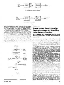
3. METHODOLOGY The genetic vehicle detection algorithm is illustrated in Figure 1. It consists of four steps: step 1: accumulation of background subtraction and thresholding; step 2: detect road markings; step 3: select ROI and step 4: detect vehicle based on back wheel structure. ith Image
i+1 th Image
n-Image Sequence
Accumulation of n-1 Background Subtractions (Ii – Ii+1); Thresholding Road Marking Detection ROI Selection Vehicle Detection Based on Back Wheel Structure Figure 1.Vehicle detection flow chart The input images have size of 1920x1080 pixels. Initially, the algorithm calculates the differences between two consecutive images in a n-sequence of images, i.e., n = 5 images in this study,
so 4 differences can be obtained, and then thresholded to form a single gray image for road marking detection. Once the two nearest road markings to the center of image are detected, they are then selected to form the left and right boundaries of ROI. The top boundary of ROI is the horizontal line in the middle of the processing image, and the bottom boundary is the bottom edge of the image. The last image in the n-image sequence is converted to gray scale and further processed with regard to ROI for detection of target vehicle. Finally, the detected vehicle is highlighted and its coordinates in the processed image are recorded.
3.1 Accumulation, Thresholding
Subtraction
∆ 12 = V1
1
,
2= 2 1= 1
+ 1 ∆ ,
,
2= 2
∆
∆
+ 2
,
− 1
,
− V2
∆
B2
2
∆ ,
∆ ,
∆
(6)
∆
Image I2 Time: t + ∆t
Image I1 Time: t B1
B2
1/ 2
∆ ,
∆
2/ 1
∆I21
,
∆I12
(2) ∆ ,
+ 2/ 1
∆
+
(3)
,
+
(4)
The change of I2 from I1 is displayed in equation (5) based on equations (3) and (4): ∆ 21 = 2/ 1
∆ ,
(1)
+ 1/ 2 ∆ ,
+ B1/V2
,
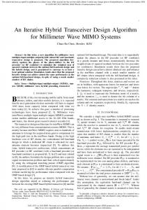
The whole process is illustrated in Figure 2, where two images I1, I2 show an object at time t and t+Δt with coordinates (x,y) and (x+Δx, y+Δy), respectively. V1 x,y, V2x+Δx,y+Δy are sub-images of I1, I2 representing an object of interest on backgrounds B1, B2. The relationship between the images is described in equation (1) (4) accordingly, B is the region that appears on both I1 and I2 and does not contain V1 x,y, V2 x+Δx,y+Δy, respectively; B1 and B2 are background parts within both I1 and I2, but outside of V1x,y, V2 x+Δx,y+Δy, respectively; B1/V2 x+Δx,y+Δy is the region of B1 over V2 at the 2nd position of object; B2/V1x,y is the region of B2 over V1 at the 1 st position of object. 1= 1
,
B1
and
In Step 1, background subtraction order is critical for highlighting changes of target object in an image sequence. By accumulating target object changes, its travel path and background scene are contrasted more significantly. In the proposed algorithm, four background subtractions are accumulated from a 5-image sequence. The resulted image is thresholded with localized threshold T which is equal to middle value between the maximum and minimum intensities of each row of lower half of the image. Dark pixels are marked with 0 intensity while bright pixels are marked with 255 intensity for 8-bit gray image. Isolated points are removed prior to the process in Step 2.
− B2/V1
,
+ 2
∆ ,
∆
− 1/ 2
∆ ,
∆
(5)
It is expressed that the difference of image I2 from image I1 is equal to the summation of two components: a subtraction of V1 from I2’s background in region of V1; a subtraction of I1’s background in region of V2 from V2. In Figure 2, B2/V1x,y is bright, V1 x,y is dark, V2 x+Δx,y+Δy is dark, B1/V2x+Δx,y+Δy is bright, the subtraction in (5) helps to highlight the first state of the object (result of subtraction is close to 255, representing bright color); the second subtraction aims to dim the second state of the object (subtraction result is close to or equal to 0, representing dark color). The equation (6) is obtained to trace the later state of an object of interest. In this case, it is used to effectively detect road markings to form ROI, and to accumulate differences between two consecutive images in an image sequence.
Figure 2. Consideration of background subtraction order
3.2 Road Marking Detection Step 2 aims to identify the nearest road markings to the middle vertical line of the last image in the sequence. It is expressed as in the following pseudo codes: Find left boundary of ROI: Loop for all rows From middle vertical line to left edge of the processing image, find middle point of white horizontal line segment Mark coordinates of the point End Loop Find right boundary of ROI: Loop for all rows From middle vertical line to right edge of the processing image, find middle point of white horizontal line segment Mark coordinates of the point End Loop
Mark and separate abrupt changes in horizontal coordinates of all found points Remove all continuous vertical points For each group of continuous points, find coefficients of line that best fits the group of points using least square method. Ignore lines representing left boundary of ROI with positive slope and lines representing right boundary of ROI with negative slope Find lines having intersections with lower edge of the processing image closest to the center of the image. The two lines represent road markings.
which the algorithm fails to detect road markings and is unable to successfully detect preceding vehicles. Step 4 remains the same. To test the suitability of the algorithm in real-time application, input image size is reduced from 1080x1920 pixels to 480x640 pixels, while there is no change to the modified algorithm. The modified algorithm is tested with 400 images from a video and all results are verified manually to calculate accuracy of the algorithm. Detection rate of the modified algorithm is reported automatically. Accuracy and detection rate of the algorithm are calculated using equations (7) and (8): =(
The algorithm can be described in following: In ROI: Threshold processing image by threshold T equivalent to middle value of maximum and minimum intensities Further locally threshold row-by-row by threshold T equaled to row’s mean intensity Find image segment that represent inverted U-shape and be nearest to the processing image’s lower edge. This image segment represents the detected vehicle. To reduce processing time for the same input image size, the algorithm is modified to use only one image to detect the front vehicle. Hence, the algorithm eliminates Step 1 and Step 2 which are time-consuming tasks. Additionally, in Step 3, a pre-defined ROI is selected initially instead of setting through road markings detected from Step 1 and Step 2. This helps to avoid situations in
(8)
A: Algorithm’s accuracy dc: Number of images in which vehicle is correctly found by the algorithm ndc: Number of images in which vehicle is not found by the algorithm correctly D: Algorithm’s detection rate t: Number of tested images d: Number of images in which vehicle is found by the algorithm
3.4 Vehicle Detection
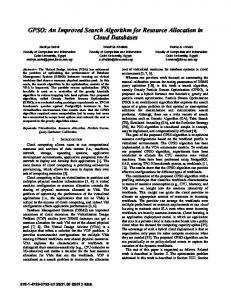
Figure 3. Back view of a vehicle with an inverted U-shape
(7)
Where
If any vehicle does not appear in ROI, it is not in the same lane as host vehicle, and therefore its detection is not necessary for AEB system; ROI helps to reduce significantly unnecessary operation of vehicle detection algorithm outside ROI and improves processing speed.
This part introduces vehicle in ROI detection based on inverted Ushape of front vehicle from back view. In image processing, the bright area has intensity close to 255 for 8-bit intensity and the dark area has intensity close to 0. For example, in Figure 3, it is obviously seen that two back wheels of the vehicle are darker than road surface. Moreover, due to lighting effect, the surrounding of the back wheels is much brighter than the line connecting to the two back wheels. Therefore, the algorithm is designed to detect position of a vehicle ahead by observing its touched points on road surface or the line mentioned above.
)/
= / 100
3.3 ROI selection ROI is formed based on returning left and right lines’ parameters from section 3.2, one horizontal line in the middle of the processed image and the lower edge of the image. The ROI serves two purposes:
+
4. RESULTS AND DISCUSSIONS Figures 4, 6, 8, 10, 12 and Figures 5, 7, 9, 11, 13 provide results from road marking detection and detected target vehicle, respectively. It shows that the target vehicle has been detected accurately when it is in ROI highlighted as the red line between two rear wheels. Table 2 shows coefficients of lines representing left and right boundaries of ROI and detected coordinates of the front vehicle. The first three sets of results show detection of vehicle within the 1 st second because images are captured with frame rate of 30 fps. The fourth set is result during the 2nd second and the last set is result during the 4 th second. The front vehicle detection is accurate when ROI is correctly formed, the algorithm does not require a tracking algorithm to keep tracking the detected vehicle. Changes in coordinates of detected vehicle are useful for detection of speed, acceleration and trajectory of the vehicle. In MATLAB environment, times taken to get results for the five sequences are 10.53s, 11.00s, 12.02s, 12.43s, and 12.11s respectively. The average processing time is 11.62s for image size of 1080x1920 pixels. The feasibility to use inverted U-shape in detecting vehicle by structural method is proved. Table 2: ROI boundary lines’ parameters: slope (a) and yintercept (b) & coordinates of detected vehicle’s center Sequence
Left ROI
Right ROI
Detected Center
al
bl
ar
br
y
x
1-5
-0.474
1299
0.509
296.3
999
890
7-11
-0.612
1364
0.553
200.3
1005
859
22-26
-0.527
1309
0.562
218.6
998
853
56-60
-0.544
1309
0.582
133.6
1030
820
98-102
-0.648
1381
0.590
15.0
1108
699
Figure 4. Detected road markings from image sequence 01-05
Figure 8. Detected road markings from image sequence 22-26
Figure 5. Detected vehicle from image 05
Figure 9. Detected vehicle from image 26
Figure 6. Detected road markings from image sequence 0711
Figure 10. Detected road markings from image sequence 5660
Figure 7. Detected vehicle from image 11
Figure 11. Detected vehicle from image 60
6. ACKNOWLEDGEMENT The authors would like to thank Universiti Teknologi Petronas (UTP) and Malaysian Institute of Road Safety Research, Malaysia for the supports during in the algorithm development.
7. REFERENCES [1]
[2] Figure 12. Detected road markings from image sequence 98102 [3]
[4]
[5]
Figure 13. Detected vehicle from image 102 The detection of touching line connecting vehicle’s back wheels is expected to provide more accurate estimation of relative speed and acceleration between host and preceding vehicles. Therefore AEB system is more accurate when estimating collision potential between the two vehicles. Results from testing the modified algorithm with 400 images show that: for input image size 1080x1920 pixels, processing time is 0.156s, the detection rate is 87.25% and the accuracy is 78%. When reducing input image size to 480x640 pixels, processing time is further reduced to 0.0297s, less than 0.033s, a typical processing time barrier for real-time application. Even though in this case, the detection rate increases slightly to 88.25%, the accuracy decreases to 73.5%. The decrease of the accuracy is mainly due to the less detailed information of the reduced-size of input images.
[6]
[7]
[8] [9] [10] [11]
5. CONCLUSION This paper proposes a robust automobile detection algorithm for AEB using simple image processing operations based on single camera. It includes background subtraction and thresholding together with information on vehicle’s inverted U-shape structure from back view. The algorithm has been evaluated successfully in MATLAB with 87.25% and 78% of detection rate and accuracy, respectively for a 1080x1920 pixel input image; 88.25% and 73.5% of detection rate and accuracy for a 480x640 pixel input image. Processing time achieved are 0.156s and 0.0297s accordingly. It indicates that algorithm is capable of performing real-time detection. In the near future the algorithm will be implemented and evaluated in real-time situation using an embedded system.
[12]
[13]
[14]
F. J. Martinez, T. Chai-Keong, J. C. Cano, C. T. Calafate, and P. Manzoni, "Emergency services in future intelligent transportation systems based on vehicular communication networks," IEEE Intelligent Transportation Systems Magazine, vol. 2, pp. 6-20, 2010. E. Coelingh, A. Eidehall, and M. Bengtsson, "Collision warning with full auto brake and pedestrian detection - a practical example of automatic emergency braking," presented at the Annual Conference on Intelligent Transportation Systems, Funchal, 2010. A. Koelpin, G. Vinci, B. Laemmle, S. Lindner, F. Barbon, and R. Weigel. (2012) Six-Port technology for traffic safety. IEEE Microwave Magazine. 118-127. J. Jin, D. Kim, J. H. Song, V. D. Nguyen, and J. W. Jeon, "Hardware architecture design for vehicle detection using a stereo camera," presented at the 11th International Conference on Control, Automation and Systems (ICCAS), Gyeonggi-do, Korea, 2011. N. Vinh Dinh, N. Thuy Tuong, N. Dung Duc, L. Sang Jun, and J. Jae Wook, "A fast evolutionary algorithm for realtime vehicle detection," IEEE Transactions on Vehicular Technology, vol. 62, pp. 2453-2468, 2013. D. Fontanelli, M. Cappelletti, and D. Macii, "A RANSACbased fast road line detection algorithm for high-speed wheeled vehicles," presented at the IEEE Instrumentation and Measurement Technology Conference (I2MTC), Binjiang, 2011. R. C. Gonzalez and R. E. Woods, Digital Image Processing, 3rd ed. Upper Saddle River, New Jersey: Pearson Education Inc., 2010. D. Phillips, Image Processing in C. 1601 West 23rd Street, Suite 200, Lawrence, Kansas 66046-0127: R & D Publications, 2000. M. S. Nixon and A. S. Aguado, Feature Extraction and Image Processing. Hungary: Academic Press, 2008. Y. Liu, X. Lu, and J. Xu, "Traffic scenes invariant vehicle detection," presented at the 9th Asian Control Conference (ASCC), Istanbul, 2013. B. Alefs and D. Schreiber, "Accurate speed measurement from vehicle trajectories using AdaBoost detection and robust template tracking," presented at the IEEE Intelligent Transportation Systems Conference, Seattle, WA, 2007. T. K. Bharathi, S. Yuvaraj, D. S. Steffi, and S. K. Perumal, "Vehicle detection in aerial surveillance using morphological shared-pixels neural (MSPN) networks," in Advanced Computing (ICoAC), 2012 Fourth International Conference on, 2012, pp. 1-8. M. Muffert, D. Pfeiffer, and U. Franke, "A stereo-vision based object tracking approach at roundabouts," Intelligent Transportation Systems Magazine, IEEE, vol. 5, pp. 22-32, 2013. C. Oh, S. G. Ritchie, and S.-T. Jeng, "Anonymous vehicle reidentification using heterogeneous detection systems," IEEE Transactions on Intelligent Transportation Systems, 2007.