S. J. Kwon and T.-S. Chung: An Efficient and Advanced Space-management Technique for Flash Memory using Reallocation Blocks
631
An Efficient and Advanced Space-management Technique for Flash Memory using Reallocation Blocks Se Jin Kwon and Tae-Sun Chung Abstract — Flash memory offers attractive features, such as non-volatile, shock resistance, fast access, and low power consumption for data storage. However, it has one main drawback of requiring an erase before updating the contents. Furthermore, flash memory can only be erased limited number of times. To overcome limitations, flash memory needs a software layer called flash translation layer (FTL). The basic function of FTL is to translate the logical address from the file system like file allocation table (FAT) to the physical address in flash memory. In this paper, a new FTL algorithm called an efficient and advanced spacemanagement technique (EAST) is proposed. EAST improves the performance by optimizing the number of log blocks, by applying the state transition, and by using reallocation blocks. The results of experiments show that EAST outperforms FAST, which is an enhanced log block scheme, particularly when the usage of flash memory is not full1. Index Terms — flash memory, FTL, embedded system, file system
I. INTRODUCTION These days, flash memories are getting much attention in research and market area due to affordable, reliable, and easy to handle memory. Cellular phones, PDAs, smart cards, MP3, digital cameras, are the popular devices where these flash memories are being used for data storage. The hardware is supported by software layer known as flash translation layer (FTL). Flash memory has some inherited problems that need to be addressed for the better performance. The inherit problems as stated in [1] are erase before rewrite, and limited number of erases. If the number of erase operation reaches to a certain number, flash memory can get damaged. FTL can handle these hardware limitations for better use. The basic function of FTL is to translate the logical addresses from the file system like file allocation table (FAT) to the physical addresses in flash memory. Reducing the number of erase operations is one of the most important issues in FTL. In NAND-type flash memory, read and write operation is done in sectors, and erase operation in blocks. One read operation in NAND-type flash memory requires 15μѕ, and one write operation requires 200μѕ. An erase operation, which is more time-consuming operation, takes 2mѕ [2]. Another important issue of FTL is the amount of RAM needed to execute the algorithm. RAM is a fast but 1
This work was supported by MIC & IITA through IT Leading R&D Support Project (2006-S-040-01) and was partially supported by Defense Acquisition Program Administration and Agency for Defense Development under contract (UD060048AD). Se Jin Kwon is with Information & Computer Engineering, Ajou University, Korea. E-mail:
[email protected]. Tae-Sun Chung is with Information & Computer Engineering, Ajou University, Korea. E-mail:
[email protected].
Contributed Paper Manuscript received December 1, 2007
high-priced memory which is used to store mapping tables. A mapping table is used for mapping logical addresses to physical addresses in the unit of sector or block. Additionally, the portion of the memory can have higher chances of getting overwritten than the rest of the memory. This can cause damage to flash memory, as there is a limit in the number of erasures. Thus, FTL should consider the wear leveling technique which is to distribute the usage of blocks evenly to extend the durability of flash memory [3] [4]. Therefore, the main purpose of FTL is to optimize the performance using the least amount of RAM, and to extend the durability by using wear-leveling technique. The popular technique is FAST [5], an enhanced log block scheme of [1]. However, we found that FAST has a problem in utilizing the space of flash memory. In our algorithm, EAST, we basically tried to solve this by optimizing the number of log blocks, by applying state transition, and by reallocating blocks efficiently. The performance has increased compared to FAST, particularly when the usage of flash memory is not full. The remainder of this paper is organized as follows. The organization of flash memory and FAST are shown in Section II. The main ideas of EAST are proposed with a detailed description in Section III. The performance evaluation of EAST and FAST is in Section IV. Finally there are the summary and final remarks in Section V. II. THE ORGANIZATION OF FLASH MEMORY AND PREVIOUS WORK A. The Organization of Flash Memory There are small block flash memory and large block flash memory depending on the size of block and sector. The size of sector is 528 bytes in small block flash memory [2], but the size of sector in large block flash memory is (2K+64) bytes [6]. This paper explains new algorithm with small block memory, but the idea of EAST can be applied to the large block flash memory as well. One block consists of 32 sectors, and the size of one sector is 528 bytes divided into 512 bytes of data area and 16 bytes of spare area. The spare area is used to store the information of block and sector. It is possible to have partial programming in the data and spare area. Partial programming is writing in the unit of byte rather than in the unit of a sector. The number of partial programming is two on the data area and three on the spare area [2]. B. Previous Works This paper is concerned with improving the performance. The existed FTLs related to performance are [1], [5], [7], [8], [9], [10], [12], and [13]. Among the previous FTLs, FAST is known to be the most optimized FTL. It is an enhanced log block scheme, which contains a fixed number of log blocks
0098 3063/08/$20.00 © 2008 IEEE
632
IEEE Transactions on Consumer Electronics, Vol. 54, No. 2, MAY 2008
as the temporary storage for overwrites [1]. By writing overwrites in the log blocks instead of erasing the data blocks, it reduces erase operations significantly. The basic idea is to make the degree of associativity between logical sectors and log blocks higher. When overwrite occurs in a data block, the write can be redirected to any log block. Further description of algorithm is described below.
Fig. 2. Merge operation of FAST
Fig. 1. Write operation of FAST
As shown in Fig. 1, the syntax for the write operation can be defined as (w LSN DLSN), which means “write the data DLSN, in the logical sector LSN.” In the figures, we assume that one block is composed of four sectors. When the write command is requested, FAST finds the physical sector to write. First, the logical block number (LBN) is calculated by dividing LSN with the number of sectors per block. The physical block number (PBN) corresponding to LBN is retrieved from the block level mapping table. Next, the offset of the retrieved physical block is decided by the remainder of division. Finally the data is written in the sector of resulting offset. For example, ①, ③, and ⑤ are written in data blocks, because target sectors are empty. If the target sector in a data block already has data, FAST writes data in the log block. There are two types of log blocks: sequential log block (SW log block) and random log block (RW log block). The condition of writing in the SW log block is either offset is zero, or sector is filling the SW log block sequentially. If neither of the condition is satisfied, data is written in the first empty sector of the RW log block. For example, ②, ④, and ⑥ have to be written in log blocks, because the target sectors are filled with data due to ①, ③, and ⑤. ② and ④ do not satisfy the condition to be written in SW log block so they are written in RW log blocks. Because ② and ④ are overwrites of ① and ③, Fig. 1 denotes the data of ① and ③ are invalid as -1. ⑥ is written in the SW log block, because the offset of ⑥ is 0. When all the sectors of the RW log blocks are filled with the data, the merge operation occurs. The merge operation in FAST is reclaiming data block by merging the RW log blocks and the data blocks.
Fig. 2 shows a merge operation of LBN 0. In the figure, we assume PBN n+1 and PBN n+2 are RW log blocks, which are filled up with data. First, the valid sectors of the data block and RW log blocks are copied to the free block, PBN n+3. Next, PBN 0, PBN n+1, and PBN n+2 are erased. Finally, the free block becomes a new data block of LBN 0, so the block mapping table is updated. There is also merge operation in the SW log block, which is called the switch operation. When the SW log block is full, the data block corresponding to the SW log block is erased, and the SW log block is changed to a new data block. The cost of the switch operation is small compared to the merge operation of RW log blocks, because it only requires one erase operation to reclaim the data block. However, we found FAST has problems in utilizing the space of flash memory. In Section III, the problems of FAST will be described, and the solution, EAST, will be proposed. III. EFFICIENT AND ADVANCED SPACE MANAGEMENT TECHNIQUE (EAST) EAST is a novel FTL algorithm, which uses the state transition applied block mapping table and reallocation blocks to use and manage space of flash memory efficiently. A. Optimizing the Number of Log Blocks In the read operation of FAST, if the sector of data block is invalid, the data needs to be searched in RW log blocks. The valid copy of target sector is found by scanning RW log blocks backward from the last sector till the system finds the required LSN in the spare area. To eliminate scanning RW log blocks on every read request, a sector mapping table of RW log blocks is required, which incurs the large RAM space requirement. The overhead grows when the number of log blocks increases. We propose to limit the number of log blocks to reduce the RAM space requirement. By limiting the number log blocks with (1), the cost of scanning RW log blocks does not exceed the cost of one erase operation. ⎢ ⎥ time of erase num of log blocks per LBN = ⎢ ⎥ (1) ⎣ time of read × num of sectors per block ⎦
Here we have considered the time required erasing a block and the time required to read a block for the calculation. The time required to read a block is calculated by multiplying the
S. J. Kwon and T.-S. Chung: An Efficient and Advanced Space-management Technique for Flash Memory using Reallocation Blocks
time required to read a sector with the number of sectors per block. Next, the number of log blocks per LBN is calculated by dividing the time required to erase a block with the time required to read a block. (1) guarantees that the time limit of all the read operation of entire log blocks within one erase operation, even though there is no sector mapping table for these log blocks. B. State Transition Applied Mapping Table If we perform different write traces at FAST, blocks having many updates usually fill below 33% before an erase operation. This is wastage of space. Our algorithm efficiently uses the remaining free sectors by applying the state transition. There are two storage techniques: in-place (I) and out-of-place (O). The in-place technique writes data in the offset of resulting PBN, but the out-of-place technique writes data not related to the offset. The in-place technique is for fast access of the read operations, and the out-of-place technique has advantage of fully utilizing the block bandwidth. EAST uses both techniques, by keeping the in-place/out-of-place flag in the spare area of each sector. Depending on this flag, the corresponding data block is decided. In EAST, each sector stores LSN in the spare area to find the logical sectors in the log blocks. It also stores the in-place/out-of-place flag in every block to use both in-place and out-of-place techniques.
633
the division. Finally, the data is written in the sector of resulting offset if the sector is empty. The write operation of ① is stored in the sector of resulting offset, because the in-place/out-of-place flag is set to in-place and the sector is empty. In the write operation of ②, the physical blocks corresponding to LBN is using the in-place technique, but the sectors of resulting offset of ② is already filled with data due ①. In this case, the retrieved PBN’s in-place/ out-of-place flag is set from in-place to out-of-place, and the data is written in the first empty sector of the retrieved PBN with writing LSN in the spare area. Therefore, the flag of PBN 0 is set to out-of-place as O, and the data of ② is written in the first empty sector. ③ is written in the first empty sector of PBN 0, because the flag is set to out-of-place. C. Efficient Utilization of Reallocation Blocks Users may use whole capacity of flash memory if memory is small, but if capacity is big, there is high possibility of not using entire memory. In 4GB (Giga Bytes) USB (Universal Serial Bus) drive, if 3.9GB is already in use, the remaining 100MB (Mega Bytes) space is not enough to save a file, such as movie files. So our algorithm uses this unused space to enhance the performance of flash memory. In this paper, unused data block, which are unrelated to write operations, are called “reallocation blocks.”
Fig. 4. Usage of Blocks in FAST
Fig. 3. State Transition Applied Mapping Table All the physical blocks are initialized by the in-place technique, when no write operation is done. When a write operation is requested, LBN is calculated by dividing LSN with the number of sectors per block as shown in Fig. 3. Assume there are only four sectors per block for the convenience of explanation. PBN corresponding to LBN is retrieved from the block mapping table. Next, the offset of the retrieved physical block is decided by the remainder of
For example, in Fig. 4, let’s assume that flash memory is composed of 10 data blocks, 3 log blocks (1 SW log blocks and 2 RW log blocks), and a free block. A small file only needing from LSN 0 to LSN 7 is stored in the flash memory. When operations are performed, the actual used physical blocks are 0, 1, 10, 11, 12, and 13, even though there are total 14 physical blocks. No matter how many times this small file is updated, PBN 2 to PBN 9 remains as unused data blocks. In this paper, we propose these unused data blocks, reallocation bocks, to be used as log blocks to reduce the multiple erase operations in available limited log blocks. In order to guarantee the capacity of flash memory, the reallocation blocks are changed from log blocks to data blocks dynamically when large number of data blocks is needed. Besides the original log blocks, the additional number of log blocks from reallocation blocks are allocated
634
IEEE Transactions on Consumer Electronics, Vol. 54, No. 2, MAY 2008
as requested from the write operation. If the updates are frequent and large, more reallocation blocks are used for log blocks. If more data blocks are required for new data writes, these allocation blocks can be switched to data blocks after merging its content. FAST can also implement the idea of utilizing reallocation blocks as in EAST, but it can have two major disadvantages. First, utilizing reallocation blocks in FAST needs to have very large RAM for a sector mapping table, because all reallocation blocks can be RW log blocks. Second, if we don’t use a sector mapping table, the cost of read operation can be very costly as mentioned in Part A of Section III.
15: return ; 16: else if no empty sector & num of free blocks >= 2 then 17: allocate a free block having the least ECN as log bl k 18: write data in the data area and LSN in the spare area ; 19: update RAM ; 20: return ; 21: else {no empty sector & num of free blocks < 2} 22: perform the merge operation ; 23: write data in the sector of the resulting offset ; 24: return ; 25: end if 26: end if 27 else if the state is set to out-of-place & num of PBNs mapped to LBN = (1) then
IV. EAST ALGORITHM A. Overview The basic idea of EAST is to have an efficient space management of flash memory. In this paper, we have implemented the following algorithm for mainly concerning the improvement in read and write time. To implement our algorithm, read, write, and merge operations are constructed as follows. B. Write Operation Initially all physical blocks are free blocks. When write procedure is initiated, data blocks and log blocks are allocated. The remaining unused data blocks are known as reallocation blocks. Each data block has in-place/out-of-place flag, which determines how data blocks are to be used. The data blocks uses the dedicated log blocks in the following conditions: if the data block is set to out-of-place and the data block is full. The maximum number of log blocks, which can be allocated to one data block, is determined by (1). Before using a new free block as a log block, EAST checks erase count number (ECN), the number of erase operations performed in a block, which is stored in the spare area of each block. This is to extend durability of flash memory by allocating blocks having least ECN as data blocks or log blocks. ECN values are updated in merge operation, and the explanation is described in the next section. 1: 2: 3: 4: 5: 6: 7: 8: 9: 10: 11: 12: 13: 14:
Algorithm 1 Write operation input: w, LSN, data Procedure FTL_write(w, LSN, data) LBN = LSN/number of sector per block ; search PBNs mapped to LBN ; search the state mapped to LBN ; if the state is set to in-place then if the sector of the resulting offset is empty then write data in the sector ; return ; else set the state to out-of-place and update RAM ; search for the empty sector in the block ; if a empty sector exists then write data in the data area and LSN in the spare area ;
28: if empty sector exists then 29: write data in the data area and LSN in the spare area ; 30: return ; 31: else 32: perform the merge operation ; 33: write data in the sector of the resulting offset ; 34: return ; 35: end if 36: else {the state is set to out-of-place & num of PBNs mapped to LBN < (1)} 37: if empty sector exists then 38: write data in data area and LSN in the spare area ; 39: return ; 40: else 41: if number of free blocks >= 2 then 42: allocate a free block having the least ECN as log 43: bl k write data in the data area and LSN in the spare area ; 44: update RAM ; 45: return ; 46: else 47: perform the merge operation ; 48 write data in the sector of the resulting offset ; 49 return ; 50: end if 51: end if 52: end if
Algorithm 1 is explained with Fig. 5. In the figure, we assume one physical block is composed of four sectors, and invalidity of sector is denoted as -1. We also assume the result of (1) is two, which means one logical block can be mapped to two physical blocks.
S. J. Kwon and T.-S. Chung: An Efficient and Advanced Space-management Technique for Flash Memory using Reallocation Blocks
635
The write operations of ⑩, ⑪, and ⑫ are written in the first empty sector of PBN 2, because the flag corresponding to LBN 1 is set to out-of-place (line 38). C. Merge Operation The merge operation in EAST is reclaiming data block by merging the data block and log blocks. By writing valid sectors of the data block and log blocks in a free block, the free block becomes a new data block, and old data and log blocks are erased as described in algorithm 2. This gives more free blocks for future use. The merge operation is initiated in following two situations.
Fig. 5. Write operation of EAST
At the initial state, all physical blocks begin with the in-place technique. When a write operation is requested, LBN is calculated by dividing LSN with the number of sectors per block. PBN corresponding to LBN is retrieved from the block mapping table, but if there is no PBN, EAST allocates a physical block containing the least ECN from the free blocks. The data is written in the sector of resulting block if the sector is empty (line 8 of Algorithm. 1). For example, in the write operation of ①, LBN 1 is decided by dividing LSN 5 with 4. There is no PBN corresponding to LBN 1, so PBN 0 is allocated for LBN 1. Finally, the data of ① is written in the offset 1 of PBN 0. If the sector of the resulting offset is filled with data, flag is changed from in-place to out-of-place, and data and LSN is filled in the first empty sector of retrieved PBN (line 14). An example of this case is shown at the write operation ⑤. LBN 1 is calculated by dividing LSN 5 with 4, and PBN 0 is retrieved corresponding to LBN 1 in the block mapping table. The sector of resulting offset 1 is unfortunately filled with data due to ①. Therefore, flag of PBN 0 is set to out-of-place, and the data of ⑤ and LSN 5 is written in the first empty sector. The data of ⑤ is written in the data area, and LSN 5 is written in the spare area. At some point, out-of-place data block won’t have any empty sector to write. EAST, then checks how many physical blocks are mapped to the corresponding LBN. If number of physical blocks is less than the result from (1), a free block containing least ECN is chosen to be an additional log block corresponding to LBN. The data is written in the first empty sector of new allocated log block, and LSN is written in the spare area (line 43). The example is shown with the write operation of ⑨. At ⑨, PBN 0 corresponding to LBN 1 is set to out-of-place, and its sectors are filled with data. There is only one physical block mapped to LBN 0, so PBN 2 is chosen to be additional log block. The data and LSN are written in PBN 2, and block mapping table is updated.
1: 2: 3: 4: 5: 6: 7: 8: 9: 10: 11: 12: 13:
Algorithm 2 Merge operation Procedure FTL_merge(LBN) choose a free block having the least ECN ; search PBNs mapped to LBN ; for each PBN mapped to LBN starting from the last PBN scan backward till valid sector appears ; if sector is valid then write sector in the free block having the least ECN ; end if end for erase PBNs mapped to LBN ; increase each PBN’s ECN ; each PBN’s state is set to in-place ; update RAM ;
Fig. 6. Merge operation of EAST
The first situation is when the number of physical blocks corresponding to one LBN equals to the result of (1). As shown in Fig. 5, LBN 1 cannot have more write operations, because the corresponding log blocks are already filled with data, and no more free space is left. This is the condition when the merge operation should be performed, which is shown in Fig. 6. LBN 1 already has the maximum number of physical blocks so it needs to choose new data block and erase the old log and data blocks. PBN 3, a free block having the least ECN, is chosen to be a new data block. The valid data from PBN 2 is written to PBN 3 in in-place. The write operation ⑬ is also written to PBN 3. PBN 0 and PBN 2 are erased and left as a free block for the future use. The ECN is incremented by one after the block is erased.
636
IEEE Transactions on Consumer Electronics, Vol. 54, No. 2, MAY 2008
Other situations are related to the number of free blocks presently available for new data block. Whenever a free block is needed to be an additional log block or a new data block, EAST checks total number of free blocks. If the total number of free blocks is less than two, a victim LBN having the largest physical block count is chosen for the merge operation. Finally, the merge operation is performed and an additional log block or a data block is allocated. D. Read Operation Algorithm 3 explains the read operation of EAST. This algorithm assumes there is not enough space of RAM to store the sector mapping table of log blocks.
1:
Algorithm 3 Read operation input: r, LSN
2:
Procedure FTL_read(r, LSN)
3:
LBN = LSN/number of sector per block ;
4:
search PBNs mapped to LBN ;
5:
search the state mapped to LBN ;
5:
if the state is set to in-place then
6:
read the sector in the resulting offset ;
7:
return ;
9: 10: 11:
Traces of Write operation
Number of Inputs
A B C D E F
Camcorder(company A) digital camera type A(company B) digital camera type B(company B) digital camera type C(company B) Linux OS digital camera(company C)
69,575 21,991 10,221 5,110 18,899 4,617
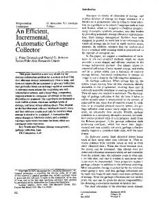
Fig. 7, 8, and 9 are results of experiments performing traces in 64MB flash memory. Fig. 7 shows the number of the erase operations when each trace is performed once. By utilizing reallocation blocks efficiently, and by using state transition, EAST outperforms FAST. The results of FAST shows decrement of the erase operations as more RW log blocks are allocated, but the number of erase operations of EAST remains same. EAST has enough blocks to optimize performance when traces are used just once so it does not need additional blocks for the improvement. Having enough blocks means the merge operation only occurs when the number of physical block corresponding to one LBN equals to (1).
else for each PBN mapped to LBN starting from the last PBN scan backward till same LSN appears in the spare area ; if same LSN appears in the spare area then
12:
read the sector ;
13:
return ;
14:
Trace
Erase operation
8:
TABLE I TRACES PERFORMED IN PERFORMANCE EVALUATION
end if
15: end if
V. PERFORMANCE EVALUATION EAST and FAST are compared to evaluate the performance. To have fair evaluation, EAST and FAST are performed in flash memory containing same number of physical blocks. Table I shows five traces used for the experiments. Trace A and E have many sequential writes, and trace C, D, and F contain more random writes than other traces.
(b) Simulation results: 12RW blocks
Erase operation
When the read operation is requested, LSN is divided by the sectors per block to calculate LBN. PBN corresponding to LBN is retrieved from the block mapping table. If the physical block is set in-place, data is read from the sector of the resulting offset. Otherwise, the spare area is read to search LSN starting from the last sector of last block mapped to LBN. Even though the sector mapping table is not used, the cost of the read operation does not exceed the cost of erase operation due to (1). If there is enough RAM to maintain the sector mapping table, the performance is improved even more.
Erase operation
(a)Simulation results: 2RW blocks
(c) Simulation results: 24RW blocks Fig. 7. Simulation environment: empty flash memory, 1 repetition of each trace.
S. J. Kwon and T.-S. Chung: An Efficient and Advanced Space-management Technique for Flash Memory using Reallocation Blocks
once, every write operation is overwrite because of the fully filled memory. As shown in Fig. 9, the switch operation is the main reason giving FAST better performance in A and D. In traces of C, D, and F, even though EAST has no advantage of using reallocation blocks, it still has better performance due to the state transition.
Total elapsed time
Erase operation
Fig. 8 is the results of performing five traces fifteen times. When same files are updated frequently, EAST outperforms FAST in trace B, C, D, and F, but FAST shows better performance in trace A and E. This occurrence is caused by the utilization of sequential log blocks. Trace A and E have small portion of random writes that repeating traces fifteen times give big advantage of using the switch operation. The switch operation is a merge operation of sequential blocks requiring just one erase operation to reclaim a new data block.
637
(a)Simulation results: 1 repetition of each trace
Erase operation
Total elapsed time
(a) Simulation results: 2RW blocks
(b) Simulation results: 15 repetitions of each trace (b) Simulation results: 12RW blocks
Erase operation
Fig. 9. Simulation environment: flash memory filled up with data.
(c) Simulation results: 24RW blocks Fig. 8. Simulation environment: empty flash memory, 15 repetitions of each trace.
As seen from Fig. 9, it is good to have the switch operation in EAST for better performances in all the cases. Both EAST and FAST are log-scheme so adding the sequential block is not difficult. However, the case of overwrite in sequential writes are rare than repetition of random writes in reality. Overall, the performance of EAST compared with FAST is better in most of cases due to innovative reallocation blocks, limiting the number of log blocks, and state transition mechanisms. This is the core achievement of our proposal. VI. CONCLUSIONS
Fig. 9 is the results of performing traces in a fully filled flash memory. It shows the total elapsed time of operations when each traces are performed. The total elapsed time is caculated by the following equation: total time = (read count × read time ) + (write count × write time ) +
(erase count × erase time )
(2)
We assume read time for 15μѕ, write time for 200μѕ, erase time for 2ms in the small block flash memory [2]. The reason for this experiment is to compare EAST and FAST without benefit of realloation blocks. Although traces are performed
EAST is an efficient and advanced space-magement technique to improve the performance of flash memory. Although FAST is well-optimized FTL algorithm among previous works, it still has problem in the efficient management of all the available spaces. EAST reduces the number of operations in flash memory by limiting the log blocks with the help of (1), implementing the state transition, and utilizing the reallocation blocks. The first part of EAST is to improve the read operation by limiting the number of log blocks which is going to decrease the size of sector mapping table, thus reducing the RAM requirements.
638
IEEE Transactions on Consumer Electronics, Vol. 54, No. 2, MAY 2008
The second idea is implementing the state transition to use both in-place and out-of-place technique in a block. This gurantees all the sectors in data block to be utilized before allocating a log block. The performance is improved compared to FAST which is clearly shown in Fig. 9. Our final implementation is to improve the performance by utilizing the reallocation block. The previous FTLs have many unused data blocks, which are not concerned with any write operations. The reallocation blocks can be assigned as the data or log blocks depending upon the situation. By having this reallocation blocks, the performance of our algorithm improved drastically as discussed in Section V with Fig. 7 and Fig. 8. ACKNOWLEDGEMENT We wish to thank Arun Ranjitkar at Ajou university for reviewing this paper.
[8] [9] [10] [11] [12] [13]
Takayuki Shinohara, “Flash memory card with block memory address arrangement,” 1999, United States Patent, no. 5,905,993. Amir Ban, “Flash file system optimized for page-mode flash technologies,” 1999, United States Patent, no. 5,937,425. Petro Estakhri, “Moving sequential sectors with a block of information in a flash architecture,” 1999, United States Patent, no. 5,930,815. Eran Gal and Sivan Toledo, “Algorithms and data structures for flash memories,” ACM Computing Surveys, 37(2), 2005. Amir Ban, “Flash file system,” 1995, United States Patent, no. 5,404,485. Bum-soo Kim, and Gui Young Lee, “Method of driving remapping in flash memory and flash architecture suitable therefor,” 2002, United States Patent, no. 6,381,176.
Se Jin Kwon received BS degree in computer engineering from Ajou University, Korea, in 2006. He is currently enrolled for master degree in database system lab. His current interests include database and flash memory.
REFERENCES [1]
[2] [3] [4] [5]
[6] [7]
Jesung Kim, Jong Min Kim, Sam H. Noh, Sang Lyul Min, and Yookun Cho, “A space-efficient flash translation layer for compact flash systems,” IEEE Transactions on Consumer Electronics, 48(2), 2002. Samsung Electronics, “Nand Flash memory,” K9F5608X0D data book, 2007. Steven E.Wells, Citrus Heights, Calif, “Method for wear leveling in a flash EEPROM memory,” 1994, United States Patent, no. 5,341,339. Sang-Wook Han, “Flash memory wear leveling system and method,” 2000, United States Patent, no. 6,016,275. Sang-Won Lee, Dong-joo Park, Tae-Sun, Dong-Ho Lee, Sangwon Park, and Ha-Joo Song, “A Log Buffer based Flash Transition Layer using Fully Associative Sector Translation,” ACM Transaction on Embedded Computing Systems, Vol.6 issue3, 2007. Samsung Electronics, “Nand Flash memory,” K9F2G08R0B data book, 2007. Tae-Sung Chung, Hyung-Seok Park, “STAFF: A flash driver algorithm minimizing block erasures,” Journal of Systems Architecture, vol.53, no.12, pp. 889-901, Dec. 2007.
Tae-Sun Chung received the B.S. degree in Computer Science from KAIST, in February 1995, and the M.S. and Ph.D. degree in Computer Science from Seoul National University, in February 1997 and August 2002, respectively. He is currently an assistant professor at School of Information and Computer Engineering at Ajou University. His current research interests include flash memory storages, XML databases, and database systems.