An Efficient Sequential Approach for Simulation of Thermal Stresses in Disc Brakes Asim Rashid1 , Niclas Strömberg∗1 1
Jönköping University, SE-55111 Jönköping, Sweden
Abstract In this paper an efficient approach to simulate thermal stresses due to frictional heating of disc brakes is presented. In the approach thermal and stress analysis are performed sequentially. The frictional heat analysis is based on the Eulerian method, which requires significantly low computational time as compared to the Lagrangian approach. Complete three-dimensional geometries of a disc and a pad are considered for the numerical simulations. The contact forces are computed at each time step taking the thermal deformations of the disc into account. The nodal temperature history is recorded at each time step and is used in sequentially coupled stress analysis, where a temperature dependent elasto-plastic material model is used to compute the stresses in a disc brake. The results show that during hard braking, high compressive stresses are generated on the disc surface in circumferential direction which cause plastic yielding. But when the disc cools down, the compressive stresses transform to tensile stresses. Such thermoplastic stress history may cause cracks on disc surface after a few braking cycles. These results are in agreement with experimental observations available in the literature. Keywords: frictional heating, thermal stresses *Corresponding author: Niclas Strömberg (
[email protected])
1.
INTRODUCTION
taking the cyclic symmetry into account and assumed a uniform heat flux. They developed and implemented a temperature dependent material model that allows different yield properties of cast iron in tension and compression. Choi and Lee [5] developed a FE model for an axisymmetric fully coupled thermoelastic contact problem. They used this model to investigate thermoelastic instability in disc brakes. In [1], Dufrénoy and Weichert developed an uncoupled 3D FE model. They simulated only one-twelfth of the disc by considering the axial and rotational symmetries of the disc and used temperature dependent material data. They confirmed the existence of residual tensile stresses on the disc surface by measuring with the hole drilling strain gage method. Gao et al. [6] developed a fully coupled 3D thermomechanical FE model to investigate the fatigue fracture in disc brakes. They assumed that thermal properties of the materials for disc and pad are invariant with temperature.
Disc brakes are used to decelerate a vehicle by pressing a set of pads against a rotating disc. It converts the kinetic energy of the moving vehicle into heat. This heat causes the disc surface temperature to rise in a short period of time. Due to these severe working conditions during operation, macrocracks might develop on the disc surface in the radial direction. Dufrénoy and Weichert [1] showed that during a brake application, compressive stresses are generated on the disc surface which cause yielding of the material. Then, when the disc is cooling, residual tensile stresses develop. Such thermoplastic loadings may cause radial macrocracks after a few braking cycles. Different numerical approaches have been used to predict the thermomechanical behavior of disc brakes. Dufrénoy and Weichert [2] implemented a twodimensional fully coupled thermomechanical algorithm. Kao et al. [3] developed a three-dimensional (3D) FE model capable of performing fully coupled thermomechanical analysis. They used this model to study hot judder in a disc brake. Koetniyom et al. [4] performed sequentially coupled thermomechanical finite element analysis of disc brakes under repeated braking conditions. They considered only a small segment of disc
Today, the usual way to simulate frictional heating of disc brakes in commercial softwares is to use the Lagrangian approach in which the finite element mesh of a disc rotates relative to a brake pad. Although this approach works well, it is not feasible due to extremely long computational times. The rotational symmetry of the disc makes it possible to model it using an Eulerian approach, in which the finite element mesh of the disc 1
does not rotate relative to the brake pad but the material flows through the mesh. This requires significantly low computational time as compared to the Lagrangian approach. Nguyen et al. [7] developed an Eulerian algorithm for sequentially coupled thermal mechanical analysis of a solid disc brake. First they performed a 3D contact calculation to determine the distribution of the pressure. Then a sequentially coupled analysis is implemented by first performing a transient heat transfer Eulerian analysis followed by a steady-state mechanical analysis. Recently, Strömberg [8] developed a finite element approach using an Eulerian framework for simulation of frictional heating in sliding contacts. In his approach, the fully coupled problem is decoupled in one mechanical contact problem and a frictional heat problem. For each time step the thermoelastic contact problem is first solved for the temperature field from the previous time step. Then, the heat transfer problem is solved for the corresponding frictional power. In another paper [9] this approach was implemented for simulating frictional heating in disc-pad systems.
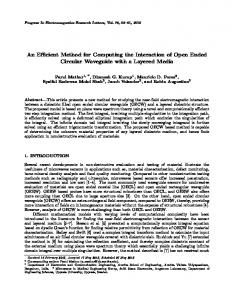
Input file
In-house software
Frictional heat analysis
ODB file
Abaqus Stress analysis ODB file Figure 1: Workflow of sequential approach to determine thermal stresses.
2.
SEQUENTIAL APPROACH
In this work, thermal stresses in ventilated disc brakes are simulated by implementing a sequential approach. First a toolbox developed by Strömberg, which is based and described in his earlier work [9], is used to perform the frictional heat analysis. In this Eulerian approach the contact pressure is not constant, but varies at each time step taking into account the thermomechanical deformations of the disc and the pad. This updated contact pressure information is used to compute heat generation and flow to the contacting bodies at each time step. In such manner, the nodal temperatures are updated accurately and their history is recorded at each time step. Then a Python script is used to write this history to an output file for subsequent use. Because the finite element mesh of the disc does not rotate relative to the pad, the contact region is always well defined and a node-to-node based approach can be adopted. This allows the mesh to be refined only in the region where the brake pad is in contact with the disc, which results in lower computational time. The output file with temperature history is then used in a sequentially coupled stress analysis performed with a temperature dependent von Mises plasticity model by using Abaqus/Standard.
The workflow of the sequential approach used for simulation of thermal stresses is shown in Fig. 1. An input file, which contains the meshed geometry with appropriate boundary conditions and loads is required for the frictional heat analysis. During this analysis linear thermo-elasticity is adopted and the problem is decoupled in two parts. In the first part, for a given temperature distribution the contact problem is solved to obtain the nodal displacements and contact pressure distribution. In the second part, for the obtained contact pressure distribution the energy balance is solved and new nodal temperatures are determined. These two equation systems are then solved sequentially and a temperature history is developed. The nodal temperatures determined at a time step are taken into account in the next time step to update the deformed geometry of the disc and pad. This is shown schematically in Fig. 2. The nodal temperature history is then written in an output file (called ODB file) by using a Python script. This temperature history is read into the Abaqus/Standard for performing sequentially coupled stress analysis. For this stress analysis, a temperature dependent von Mises plasticity model is used.
The results show the presence of residual tensile stresses on the disc surface after it cools down, which surpass the yield limit of material during a hard braking. The sequential approach has proved tremendously cheap in terms of computational time when compared to fully coupled Lagrangian approach. This is demonstrated by presenting numerical results.
3.
NUMERICAL RESULTS
The assembly of the disc-pad system considered in this paper is shown in Fig. 3. The disc is geometrically symmetric about a plane normal to the z-axis. It is assumed that thermomechanical loads applied to the system are symmetric so only half of this assembly is considered 2
Specify initial temperatures of disc and pad
0
Thermoelastic contact problem is solved and contact pressure distribution is determined
Support Plate
∆
Figure 4: Brake pad with support plate. Heat transfer problem is solved and new nodal temperatures are determined.
Z Y X
Figure 2: Sequential approach used during frictional heat analysis to determine temperature history.
for the simulation and symmetry constraints are applied on the nodes lying on the symmetry plane. Some detailed geometry at the inner radius has been removed to simplify the model as that is not important for this analysis. The displacements along x and y directions of the nodes located at the inner radius of the disc are set to zero. All the surfaces of the disc, except the one lying on the the symmetry plane are considered to lose heat by convection.
In Fig. 6, temperature of the disc surface is shown for the first simulation. A brake force of 24.5 [kN] is applied for 45 [s] on the back surface of support plate. The angular velocity of the disc is 45 [rad/s] and held constant throughout the simulation. The force is ramped up by using a log-sigmoid function during 20 time increments and then held constant for next 70 increments with time step = 0.5 [s]. The friction coefficient is µ = 0.3, contact conductance is ϕ = 0.1 [W/NK] and convection coefficient is set to 50 [W/m2 K]. The disc assembly is meshed with 270194 elements. The total CPU time is 4272 [s] on a workstation with Intel Xeon X5672 3.20 GHz processor. In Fig. 7, a graph of nodal temperatures is shown for the second simulation. The nodes of the disc chosen for this plot are located at 180◦ from the middle of the pad. In
Y
Z
Z
X
Figure 3: An assembly of the disc-pad system. X
Fig. 5 (only a small portion of the disc is shown). This is an advantage of the Eulerian approach because the finite element mesh of the disc does not rotate relative to the brake pad but the material flows through the mesh. In Lagrangian approach fine mesh should be applied on the complete surface of the disc because the finite element mesh of the disc rotates relative to the brake pad or some adaptive strategy should have to be applied. All the parts considered for the simulation are meshed with 4-node linear tetrahedron elements in HyperMesh (HyperWorks 10.0). These meshed parts are then used to prepare input file with boundary conditions and loads in Abaqus/CAE. Now the results of two frictional heat simulations will be described. Results from the second one will be used to compute thermal stresses in the disc.
The brake pad is supported by a steel plate at the back side as shown in Fig. 4. Some detailed geometry of the support plate which is not necessary for the simulation has been removed. Two cylindrical pins apply a normal force on the back surface of the support plate which transmits it to the pad. Displacements at the back surface of the support plate, other than along the force direction, are fixed. Furthermore temperature is set to zero on the back surface. The disc is meshed such that it has smaller elements where it contacts the pad as shown in
Y
Brake Pad
Figure 5: Mesh of the disc.
3
NT11 1129 1071 1014 956 899 841 784 726 669 612 554 497 439
Figure 6: After the brake application, a ring of high temperature develops on the disc surface.
this case the brake force of 24.5 [kN] is applied for 20 [s]. The angular velocity of disc is 45 [rad/s] and held constant throughout the simulation. The force on the support plate is ramped up by using a log-sigmoid function during 20 time increments and then held constant for next 80 increments with time step = 0.2 [s]. The friction coefficient is µ = 0.3, contact conductance is ϕ = 0.1 [W/NK] and convection coefficient is set to 50 [W/m2 K]. After braking, the disc is cooled for another 5000 [s] with a time step of 5 [s]. In the legend of this figure, R means the radius of node in [mm] for which the curve is plotted. Here it is important to mention that the outer radius of the disc is 218.3 [mm] and inner radius is 112.3 [mm]. Total time, i.e. sum of the braking and the cooling time has been scaled so that it appears as a unit on the time scale. It is evident that the temperature gradient along the radius of the disc disappears very quickly after the brake operation ends.
imported to Abaqus and a stress analysis is performed. The total CPU time for the frictional heat and stress analysis is 8979 [s] and 5602 [s] respectively, on a workstation with Intel Xeon X5672 3.20 GHz processor. In Fig. 8, a graph of circumferential stresses on the disc surface is shown. It can be seen that as the brake is applied, compressive stresses are generated. But after the disc cools down, they transform into tensile stresses. In Fig. 9, a graph of von Mises stresses on the disc surface is shown which elaborates that von Mises stresses go beyond the yield limit of material. So the material is deformed permanently first in compression when the brake is applied and then in tension when the disc cools down. A graph of circumferential plastic strains of the disc material at the surface is shown in Fig. 10. This shows reversing trend during cooling down of the disc because the yielding direction is opposite to that during the braking operation.
The temperature history ofODB: this frictional heat Abaqus/Standard analysis is Brake3P.odb 6.9−EF1
[x1.E9] 0.20
500.
Step: heat, Step with own NT11 data Increment 90: Step Time = 0.989010989011 0.15 R 130.3 Primary Var: NT11 R 147.4 0.10 not set R163.9 Deformed Var: not set Deformation Scale Factor:
400. Y
R 180.1 300.
0.05
Z X
Stress
Temperature
Thu Jan 26 08:56:30 W. Europe Standard Time 2012
200.
0.00 −0.05 R 130.3 R 147.4 R 163.9 R 180.1
−0.10
100. −0.15
0. 0.00
0.20
0.40
0.60
0.80
−0.20 0.00
1.00
0.20
0.40
0.60
0.80
1.00
Time
Time
Figure 7: Nodal temperatures on the disc surface.
Figure 8: Circumferential stresses on the disc surface.
4
[x1.E9] 0.20
[x1.E9] 0.20 0.15
0.15
0.10
Stress
Stress
0.05
0.10
0.00 −0.05
R 130.3 R 147.4 R 163.9 R 180.1
0.05
0.00 0.00
0.20
0.40
0.60
0.80
R 130.3 R 147.4 R 163.9 R 180.1
−0.10 −0.15 −0.20 0.00
1.00
Time
0.20
0.40
0.60
0.80
1.00
Time
Figure 9: von Mises stresses on the disc surface.
Figure 11: Radial stresses on the disc surface.
Compressive stresses on the disc surface can be explained by higher expansion of the surface material due to higher temperature. The frictional heat causes the disc surface temperature to rise in a short period of time as compared to the inner of the disc as shown in Fig. 6. So the surface expands more than the disc inner and due to closed shape of the disc, compressive stresses are generated on the surface. When these stresses surpass the yield limit, the material deforms permanently. But on cooling down of the disc, the compressive stresses transform into tensile stresses because the material has already yielded in compression. At some nodes, magnitude of the compressive stresses starts decreasing even though the temperature is increasing, it can be attributed partly to the reduction of hardening at higher temperatures. Depending upon the magnitude, the residual tensile stresses in circumferential direction may cause the initiation of radial microcracks on the disc surface.
tude of the compressive stresses starts decreasing even though the temperature is increasing. This can be explained by the higher expansion of the surface material in radial direction as compared to the inner of the disc in the beginning but as the heat flows to the inner, it also expands radially. So due to the reduction in difference in the expansions, the compressive stresses start reducing in magnitude. By comparing with Fig. 8, it can be concluded that, although the radial stresses follow the same trend as the circumferential stresses, their magnitude is lower. This is in agreement with the observation that radial microcracks on disc surfaces are more marked than circumferential ones, even when macroscopic cracks do not appear [1].
4.
In this work a sequential approach has been implemented to study thermal stresses in disc brakes. Frictional heat analysis is performed in an in-house software based on the Eulerian approach and stress analysis is performed in commercial software, Abaqus, which uses thermal history from the frictional heat analysis as input. This method has proved tremendously cheap in terms of computational time when compared to the fully coupled Lagrangian approach. The temperatures predicted by the in-house software have been compared with the temperatures recorded by a thermal imaging camera during a physical test and found to be fairly close. The stress analysis results show that during a hard braking, high compressive stresses are generated on the disc surface which cause the plastic yielding. But when the disc cools down, the compressive stresses transform to tensile stresses. The results also predict higher residual tensile stresses in circumferential than radial direction, which is in agreement with the observation that radial microcracks on disc surfaces are more marked than circumferential ones, even when macroscopic cracks do
In Fig. 11, a graph of radial stresses on the disc surface is shown. It can be seen that as the brake is applied, compressive stresses are generated at some nodes. But after the disc is cooled down, these stresses transform into tensile stresses. It can also be seen that magni[x1.E−3] 0.0 −0.5
R 130.3 R 147.4 R 163.9 R 180.1
−1.0
Strain
−1.5 −2.0 −2.5 −3.0 −3.5 −4.0 −4.5 0.00
0.20
0.40
0.60
0.80
CONCLUDING REMARKS
1.00
Time
Figure 10: Circumferential plastic strains on the disc surface.
5
momechanical coupling. Journal of Tribology 129(3) (2007) pp. 536–543. 7. T. Nguyen-Tajan, J. Thomas, M. Houari, Z.-Z. Du, M. Snyma, J. Nagtegaal, H. Maitournam, A Computationally Efficient Eulerian Algorithm for Sequentially Coupled Thermal Mechanical Analysis of a Solid Brake Disc. ABAQUS Users’ Conference, Stockholm, Sweden (May 2005) pp. 363 – 372. 8. N. Strömberg, Development and implementation of an Eulerian aproach for efficient simulation of frictional heating in sliding contacts. IV International Conference on Computational methods for Coupled Problems in Science and Engineering Eccomas, 2022 June, Kos, Greece, 2011. 9. N. Strömberg, An Eulerian approach for simulating frictional heating in disc-pad systems. European Journal of Mechanics - A/Solids 30(5) (2011) pp. 673 – 683.
not appear [1]. Such thermoplastic stress history may cause the radial macrocracks on disc surface after a few braking cycles. In future this sequential approach can be used to study the fatigue life of a disc with a reasonable simulation time. It can be very useful when studying new designs for real disc brake systems. During the frictional heat analysis, temperature independent material data has been used. For more realistic results, temperature dependent material data should be used. At present the in-house software assumes constant angular velocity of the disc but in future it could also be extended to non-constant angular velocities. For stress analysis, a material model has been used that assumes the same behavior of the material both in tension and compression but in reality cast iron has different properties in tension and compression. So in future it would be advantageous to implement a material model incorporating the different behavior of cast iron in tension and compression. Such a material model has been developed by Koetniyom et al. [4].
5.
ACKNOWLEDGEMENT
This project was financed by Vinnova (FFI-Strategic Vehicle Research and Innovation) and Volvo 3P.
References 1. P. Dufrénoy, D. Weichert, A thermomechanical model for the analysis of disc brake fracture mechanisms. Journal of Thermal Stresses 26(8) (2003) pp. 815–828. 2. P. Dufrénoy, D. Weichert, Prediction of railway disc brake temperatures taking the bearing surface variations into account. Proceedings of the Institution of Mechanical Engineers, Part F: Journal of Rail and Rapid Transit 209(2) (1995) pp. 67–76. 3. T. Kao, J. Richmond, A. Douarre, Brake disc hot spotting and thermal judder: an experimental and finite element study. International Journal of Vehicle Design 23(3) (2000) pp. 276–296. 4. S. Koetniyom, P. Brooks, D. Barton, The development of a material model for cast iron that can be used for brake system analysis. Proceedings of the Institution of Mechanical Engineers, Part D: Journal of Automobile Engineering 216(5) (2002) pp. 349– 362. 5. J. Choi, I. Lee, Finite element analysis of transient thermoelastic behaviors in disk brakes. Wear 257(12) (2004) pp. 47–58. 6. C. Gao, J. Huang, X. Lin, X. Tang, Stress analysis of thermal fatigue fracture of brake disks based on ther6