IEEE TRANSACTIONS ON MICROWAVE THEORY AND TECHNIQUES, VOL. 62, NO. 10, OCTOBER 2014
2423
An Extraction of Two-Port Noise Parameters From Measured Noise Powers Using an Extended Six-Port Network Abdul-Rahman Ahmed and Kyung-Whan Yeom, Member, IEEE
Abstract—In this paper, we present a formulation for extracting the noise wave correlation matrix of a linear two-port device-under-test (DUT) from measured noise powers using a designed six-port network. The noise powers are measured using a conventional noise figure analyzer. The extracted noise wave correlation matrix can then be converted into conventional two-port noise parameters. The proposed measurement equipment is very simple and leads to a very low cost. The proposed method is experimentally verified through measurements of various DUT samples. Index Terms—Calibration, noise figure, noise parameters, noise waves correlation matrix, six-port network.
I. INTRODUCTION
T
HE NOISE figure, a popular measure of the noise performance of a linear two-port device, depends on the source impedance seen from the device [1]. From the well-established theory of linear noisy two-ports, the dependence of the noise figure on the source impedance can be described using four noise parameters. The four noise parameters consist of two real parameters, noise resistance and minimum noise figure , and a complex parameter, optimum source reflection coefficient . Knowledge of the noise parameters of linear two-port active devices is crucial in low-noise amplifier (LNA) design as well as in active device characterization. Conventionally, the noise parameters for a linear two-port device-under-test (DUT) are measured using a mechanical impedance tuner. The mechanical impedance tuner is used to vary the source impedance seen from the DUT. In [1], is found by experimental search for the minimum noise figure using the mechanical impedance tuner and the that results in this minimum. One or several nonsingular noise figure measurements then result in the complete determination of the noise parameters. The noise parameters determined by this technique generally show fluctuation and are inaccurate. To overcome the inaccuracy, various noise parameter extraction methods employing least square fitting or curve fitting for the nonsingular measured data were proposed [2]–[5]. Escotte et Manuscript received February 13, 2014; revised May 06, 2014, June 23, 2014, and July 25, 2014; accepted July 29, 2014. Date of publication August 19, 2014; date of current version October 02, 2014. This work was supported by the Korean Government under the National Research Foundation of Korea (KRF2014-010440). The authors are with the Department of Radio Science and Engineering, Chungnam National University, Daejeon 305-764, Korea (e-mail:
[email protected];
[email protected]). Digital Object Identifier 10.1109/TMTT.2014.2345693
al. [6], provide an extensive comparison of various tuner-based methods. Belostotski and Haslett [7] showed that the accuracy of such techniques employing least square fitting is dominantly limited by the excess noise ratio (ENR) of the noise source. The previously mentioned techniques of noise parameter measurement, which are based on the mechanical impedance tuner, depend on scalar noise-figure measurements. It is shown in [8] that the accuracy of the noise parameters measurement can be improved with the complement of vector network measurement. The mechanical impedance tuner based technique with the aid of a vector network analyzer is currently the most popular commercial noise parameter measurement setups [9], [10]. Recently, the noise parameter measurement setup using the mechanical impedance tuner has shown remarkable progress. A considerable improvement in measurement speed and enhanced measurement accuracy has been reported [11]. However, such a combination of equipment consequently results in a high-cost measurement setup. One of the functions of the network analyzer in the commercial noise parameter measurement setup is to provide information about the source impedance seen from the DUT, which is tuned by the mechanical impedance tuner. A low-cost alternative was proposed in the pioneering research of [12] and [13]. The six-port network originally proposed by Engen [14] can be used as an alternative network analyzer. In [12] and [13], the source impedance is also tuned by a mechanical impedance tuner and the six-port network functioning as a reflectometer provides information on the source impedance tuned by the mechanical impedance tuner. Thus, they can be classified as low-cost version of the modern network analyzer based noise parameter measurement setups. Generally, the extraction of broadband noise parameters is possible with the commercial network analyzer based noise parameter measurement setups. However, the bulky nature of the mechanical impedance tuner causes problems in connecting directly to on-wafer type DUT. The mechanical impedance tuners are generally connected to an on-wafer probe station using low-loss cables. As the insertion loss of the cables increases with frequency, it becomes difficult to synthesize highly reflective loads in millimeter and sub-millimeter-wave bands [15]. Several other variations of the mechanical impedance tuner based technique have appeared due to the increasing demand for on-wafer noise parameter measurements. Rather than the bulky impedance tuner, the source impedance is varied using a sliding short [16], p-i-n diode switch [17], programmable attenuator, and a short circuit [18], and other multiple standard
0018-9480 © 2014 IEEE. Personal use is permitted, but republication/redistribution requires IEEE permission. See http://www.ieee.org/publications_standards/publications/rights/index.html for more information.
2424
IEEE TRANSACTIONS ON MICROWAVE THEORY AND TECHNIQUES, VOL. 62, NO. 10, OCTOBER 2014
terminations [19] at the cost of radial coverage of the Smith chart. Another problem of the mechanical impedance tuner based methods and their variations may be that the DUT directly sees the source impedance tuned by the mechanical impedance tuner. Highly reflective source impedance can be seen by the DUT and it may cause oscillation in the case of unstable DUTs. Several studies for the extraction of noise parameters without the need for impedance tuner have been reported. Dambrine et al. [20] extracted the noise parameters of MESFETs and HEMTs using the frequency dependence of the noise figure measured at a 50- source impedance. Welring et al. proposed a technique for extracting the noise parameters of MESFETs and HEMTs using spectral parametric modeling [21]. These two require some device specific assumptions. Hu and Weinreb proposed an extraction using a set of matched and mismatched noise temperatures measured within a surrounding frequency sampling window [22]. The method proposed by Hu and Weinreb is general and requires no assumptions on the DUT. A novel method, which fundamentally removed the mechanical impedance tuner, has been addressed by Wedge and Rutledge [23]. The noise wave correlation matrix is measured instead of the noise parameters. Two noise sources are employed in their measurement setup and the noise wave correlation matrix is then converted into the conventional noise parameters. Wedge has also proposed the extraction of the noise correlation matrix using a six-port network in the suggestion for future work in his Ph.D. dissertation [24] and the idea was patented in 1992 [25]. The advantage of the six-port method is that the noise parameters can be directly measured without tuning the impedances. In addition, the DUT is not exposed to impedance changes as in the case of the mechanical impedance tuner based technique. However, no further implementation or measurement of the noise wave correlation matrix using the six-port network is to be found in the literature. To the authors’ knowledge, this is the first practical noise parameter measurement setup that uses the six-port network in the extraction of the noise correlation matrix of a DUT. The real challenge in the implementation of this technique is the practical calibration of the general six-port network. Calibration techniques for the six-port network that have appeared in the literature so far are relevant to reflectometry [13], and is not related to the extraction of the noise correlation matrix. In this paper, guided by the above considerations, we present a measurement setup for extracting the noise wave correlation matrix of a linear two-port using an extended six-port network (eight-port network) in Section I. In Section II, the formulation necessary for calibrating the general eight-port network is presented. In Section III, the proposed method is verified through the measurements of various DUT samples. The measured results show that the proposed method works successfully. II. MEASUREMENT SYSTEM DESCRIPTION A. Measurement Setup The measurement setup and its photographs are shown in Fig. 1(a) and (b).
The six-port network is fabricated using printed circuit board (PCB) technology and is composed of five conventional power dividers and a 90 -hybrid, as shown in Fig. 1(c). The noise figure analyzer (NFA) used is N8975A from Agilent Technologies. The noise figure, as well as the gain measured using the NFA severely fluctuates when the gain of the DUT is very low [25]. The three LNAs in Fig. 1, ZX60-542LN from Mini Circuits, are for gain boosting. The operating frequency range of the selected LNA according to the datasheet is 4.5–5.5 GHz and their dc voltages are supplied using a multiple output dc power supply 6626A from Agilent Technologies. The personal computer (PC) is for instrument control and data acquisition by a general-purpose interface bus (GPIB). The VEE interface program from Agilent Technologies is used in the control and data acquisition. The computation for calibration and the extraction of the noise parameters is carried out using a MATLAB script embedded within the VEE program. Fig. 2 shows the designation of port numbers and the noise wave definitions of the measurement setup shown in Fig. 1. Ports 1–4 are used for measuring noise output powers. The input powers from points A and B in Fig. 2 are equally divided by power dividers and appear at ports 1 and 4, respectively. Thus, the input power levels from points A and B can be determined by measuring the powers at ports 1 and 4, respectively. The powers at ports 2 and 3 become the in- and quadraturephase sum of two signals injected from A and B, respectively. Since the input power levels from points A and B are previously determined using the powers at ports 1 and 4, the powers corresponding to the in-phase and quadrature phased products of the two input signals can be determined by measuring the powers at ports 2 and 3. From the in-phase and quadrature phased products of the two signals, the real and imaginary parts corresponding to the product of the two input signals can be determined and the correlation of the two noise signals can be obtained as a result. Thus, the complete noise correlation matrix can be obtained by measuring the four powers at ports 1–4. The four outputs from ports 1–4 of the six-port network are connected to the absorptive single-pole four-throw (SP4T) switch, an MSP4TA-18 from Mini-Circuits for convenience of measurement. Thus, the output selected by the SP4T switch is connected to the NFA and the other ports are connected to the 50- terminations inside the SP4T switch. The NFA measures the noise powers of a given DUT with the aid of an external noise source. Two additional ports, ports 5 and 6, are created using a pair of 13-dB directional couplers 102040013K from Krytar, which enables simultaneous connections for both the noise source and DUT. As a result, an eight-port network is formed with both the six-port network and the two directional couplers. The noise source used is N4002, which has an ENR of 14–17 dB from Agilent Technologies. Notably, the NFA does not support two simultaneous noise sources. Thus, the measurement of the output noise powers is carried out with the noise source connected alternately to ports 5 and 6. The necessity for the two 13-dB couplers is relevant to the isolation property of the six-port network. When the noise source is connected to port 5, a negligible noise source power is delivered to port 4. In the case of an ideal six-port network
AHMED AND YEOM: EXTRACTION OF TWO-PORT NOISE PARAMETERS FROM MEASURED NOISE POWERS
2425
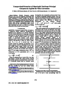
Fig. 2. Eight-port network and associated noise wave definitions.
the NFA and the measured noise power of the two-port network formed between ports 4 and 5 are inaccurate. Conversely, the measured noise power of the two-port network formed between ports 6 and 1 are inaccurate when the noise source is connected to port 6. Therefore, the inclusion of the two 13-dB couplers is necessary. The 13-dB diectional coupler reduces the noise power incident from the noise source, but the noise ratio of the hot and cold states is preserved. In the case when the noise source is connected to port 5, the combined power of and the coupled noise source power appear at point A in Fig. 2. The hot state noise power of the noise source thus should be greater than otherwise the NFA cannot accurately measure the noise figure and gain. One can reach the conclusion that the hot state noise power should be greater than and through similar reasoning. Ideally, the coupling of the direction coupler must be optimized taking the levels of and of a DUT into consideration. The coupling of 13 dB in the setup of Fig. 1 may be a good choice for DUTs with lower and , but the coupling should be lower for DUTs with higher or . B. Eight-Port -Parameters
Fig. 1. (a) Measurement setup for noise parameters and photographs of the: (b) measurement setup and (c) six-port network.
composed of ideal power dividers and 90 -hybrid, the delivered power to port 4 is 0, as can be inferred from Fig. 2. The delivered noise source power is mostly below the noise floor of
The computation of the noise parameters of a given DUT, presented in Section II-C, requires the -parameters of the DUT and the eight-port network, which are pre-measured using an Agilent PNA-L5230A four-port network analyzer and stored as data for the MATLAB program. The -parameters of the eight-port network can be obtained by separately measuring and combining those of the SP4T and eight-port network. Alternatively, the -parameters of the eight-port network shown in Fig. 2, which actually reduces into a five-port network due to the SP4T, can be measured directly using the four-port network analyzer. The five-port -parameters can be formed by combining two independent sets of four-port -parameters. The SP4T switch has four states leading to four independent sets of
2426
IEEE TRANSACTIONS ON MICROWAVE THEORY AND TECHNIQUES, VOL. 62, NO. 10, OCTOBER 2014
the five-port -parameters. Note that the SP4T basically eliminates the laborious job of connections and disconnections in the measurement and the four sets of five-port -parameters can approximately be described by those of a virtual eight-port network, in which port numbers 1–4 are assigned to switch states. There is a difference between the virtual eight-port -parameters and that obtained by combining the two separately measured -parameters for the eight-port network and SP4T switch. In the case of the former, for ports 1–4, 1) ( , – , – ), which corresponds to the transmission between ports and cannot be measured directly as ports 1–4 are not directly accessible. They are approximated as . 2) Due to nonuniform and incomplete terminations inside the SP4T, the other elements of the -parameters excluding ( – , – ) may depend on the states of the SP4T. On the second problem, the measured votlage standing-wave ratios (VSWRs) of the four inputs of the SP4T, with its output terminated by 50 , are found to be almost identical. The same fact can be found in the datasheet. Thus, the changes of the other elements of the -parameters excluding ( – , – ) with respect to the SP4T states are negligible. The first problem is relevant to the properties of ( – , – ) corresponding to the transmissions between ports and . They are found to be small, from the measurement of the passive six-port network shown in Fig. 2, a fact that can also be deduced from Fig. 2. The peak value of the isolation, which we measured from the separately fabricated six-port network, is about 27 dB for a frequency range of 4.5–5.5 GHz. The contributions of the noise powers due to the terminations inside the SP4T can be neglected compared with the amplified DUT noise. Therefore, the virtual eight-port -parameters without the SP4T formed using four sets of the five-port -parameters can be used to compute the noise powers. In the virtual eight-port -parameter description, the noises due to the terminations inside the SP4T are treated like external thermal noise sources. C. Designation of Noise Waves The designations of the noise waves for the eight-port network and those for the two-port DUT are shown in Fig. 2. Due to internal noise sources, noise voltages are developed across 50- terminations connected to ports and the noise waves in Fig. 2 represent the normalized volatges across 50- terminations. In the case of the eight-port network, noise waves and denote noise waves incident on the two input ports 7 and 8 and they are represented by vector . Noise waves and originate mainly from the 13-dB directional couplers, the connection cables, and the input noise waves from LNA1 and LNA2. Note that there is no correlation between and . The noise waves appearing at ports 5 and 6 are denoted as and . These are denoted by vector . Noise waves as and originate from the same noise sources as and . The noise waves appearing at ports 1–4 are denoted as – and represented by vector . The noise waves – originate
from the internal noises of the passive six-port network and the output noises of LNA1 and LNA2. The noises generated by the passive six-port network are correlated. As a result, noise waves – are correlated. Furthermore, taking the noise source origins into consideration, one can find that a correlation exists between and . The noise sources due to the terminations inside the SP4T are not included in the noise wave representation and they are treated as external noise sources. The noise waves of the two-port DUT is represented by and . These are represented by vector . When the eightport network and two-port DUT are connected, the measured output noise powers from are a superposition of the previously defined noise waves and the externally applied noise sources scattered by the eight-port network. The contributions of the external noise source power and the noise powers due to and should be removed to obtain the desired noise wave correlation matrix of and . Thus, it is necessary to caliberate the eight-port network, in order to determine the noise power due solely to the DUT. This is treated in Section III. Once calibrated, the DUT noise correlation matrix and subsequently its noise parameters can then be determined. III. FORMULATION Representing the virtual eight-port -parameters described in Section II as , the relationship between output wave vector and incident wave vector can be expressed as (1) Here, vector represents the noise emanating from the external terminations and is scattered by the virtual eight-port network, and thus contributes to . The noise wave vector can be interpreted as the excess noise that the virtual eight-port network delivers to its terminations. Equation (1) can be partitioned as
(2)
Subscripts is used for ports 1–4, for ports 7 and 8, and for ports 5 and 6, respectively. A similar relationship for the DUT can be expressed as (3) represents the two-port DUT -parameters. The vecHere, tors , , and are similarly defined as in (1). When the DUT in (3) is connected to the input ports (ports 7 and 8), , which represent the noise wave vector delivered to the measurement ports (ports 1–4), can be derived from (2) and expressed as (4) In (4), represents the thermal noise contribution from the terminations inside the SP4T as the noises emanating from the terminations of the SP4T are treated like external noise sources, as previously explained in Section II. represents
AHMED AND YEOM: EXTRACTION OF TWO-PORT NOISE PARAMETERS FROM MEASURED NOISE POWERS
the thermal noise contribution from the noise source and 50- termination. As previously mentioned, represents the noise wave vector of the virtual eight-port network incident directly on the measurement ports. The term represents the contribution of the reflected due to mismatch. The term in (4) represents the noise contribution from the DUT. The matrices , , , and can be expressed using the partitioned matrices in (2) as 4
2 matrix
4
4 matrix
4
2 matrix
4
2 matrix
Here, the matrix represents a 2 2 identity matrix. Note that the matrices are functions of . Equation (4) is the governing equation for the measurement and represents the relationship between possible external noise sources and the noise waves delivered to ports 1–4 from the virtual eight-port network. Since and are thermal noise sources, their contribution to can easily be determined using (4). Noise sources and are independent of each other and are thus uncorrelated. The remaining and are correlated. Thus, the correlation matrix of and should be determined a priori. Once these noise contributions are determined, can be obtained and the noise correlation matrix of a DUT can be determined. The noise parameters of the DUT can then be determined from the noise correlation matrix. A. Determination of From (2), can be determined by measuring noise wave across 50- loads. For the determination of , ports 7 and 8 (DUT ports) are terminated by 50- loads and the noise source is applied to port 5 with port 6 terminated in a 50- load. The noise powers are then measured at ports 1–4. Alternately, the noise source is applied to port 6 and the noise power measurement can be taken at ports 1–4. Note that the contributions of and for such a termination condition do not appear at the measurement ports. The noise factors and gains successively measured at the four measurement ports are denoted by and and likewise and , respectively, – . It should be noted that the measured gains using an NFA is the insertion power gains. Using the measured noise factors and gains when the noise source is applied to port 5, the noise powers delivered to ports 1–4 can be expressed as
2427
Thus, and can be defined for the alternative cases of noise source at ports 5 and 6 as and
(6)
The noise powers in (5) and (6) correspond to those when all ports of the virtual eight-port network are terminated in 50matched loads. Thus, for 1–4, and . However, they may differ slightly due to measurement errors. Averaging the measured normalized noise powers evens out the disparity. Thus, the two measured noise powers at ports 2 and 3 are averaged. On the other hand, the noise power at port 1 is determined using alone and similarly the noise power at port 4 is determined using alone. As shown in Fig. 2, the gain between ports 4 and 5 is extremely low. As a result, the noise power measured with the NFA for this path (port 5–port 4) include significant errors and are unreliable due to the very low gain. The same is true for ports 1 and 6. The normalized noise power vector thus averaged is denoted as (7) represents transpose. Here, The normalized noise power vector given by (7) corresponds to when all the ports of the virtual eight-port network are terminated by 50- loads. Thus, from (2), for this termination condition can be expressed as (8) The vectors , , and are independent and their available noise power density is given by . The noise powers at the measurement ports can be expanded as
(9) denotes the diagonal of a matrix and repThe operation resents conjugate transpose. in (9) is the correlation matrix of normalized to thermal noise power . Using (9), can be determined as
(10)
(5)
represents the measured noise power normalized by Here, , the thermal noise power at a temperature of K.
, , , and are elements of . In (10), the Here, last term is necessary because the port used in the noise power measurement should be noiseless. The normalized noise power vector in (7) represents the noise power delivered to a noiseless 50- load. On the other hand, all the thermal noises in (8) are incident on the virtual eight-port network. Thus, should be 0 in the computation of in (9). The contribution of
2428
IEEE TRANSACTIONS ON MICROWAVE THEORY AND TECHNIQUES, VOL. 62, NO. 10, OCTOBER 2014
to appears due to the reflection at port 1. Since all the ports are terminated by 50 , should be subtracted from the computed result of . The computed results for for other ports are similarly corrected. Note that the computed in (10) only includes the self-correlation terms of and is denoted as
(11)
B. Determination of
and Its Correlation With
The noise wave vector can be reflected when highly reflective loads are connected to ports 7 and 8 in Fig. 2 and will thus appear at the measurement ports 1–4. The noise powers at the measurement ports change due to the noise wave vector as well as due to its correlation with . Thus, and its correlation with can be determined by measuring the changes in the noise powers at the measurement ports resulting from the reflections of . However, the direct determination of the correlation between and is a formidable task due to a large number (about 16) of unknown correlations. Furthermore, it is difficult to directly describe using the output noises of LNA1 and LNA2 and . As previously explained, is mainly composed of the noises emanating from the inputs of LNA1 and LNA2 in Fig. 2. On the other hand, noise wave vector is the superposition of the noises emanating from the outputs of LNA1 and LNA2 and the correlated noises emanating from the passive six-port network. Thus, the noise wave vector obviously has no correlation with the noises generated in the passive six-port network and has correlation only with the noise emanating from the outputs of LNA1 and LNA2. Note that the output noises of LNA1 and LNA2 can be converted into the noises applied to ports 7 and 8 of the eight-port network. Noise waves and in Fig. 2 incident at ports 7 and 8 of the eight-port network correspond to the converted output noises of LNA1 and LNA2. Since noise waves and are defined when all the ports of the eight network are terminated by 50- loads, and can be interpreted as the excess noises supplied from the 50- terminations connected to ports 7 and 8. can then be expressed by a linear combination of and as
vectors and in (12) can be interpreted as the column partition of . Thus,
4
2 matrix
(13)
and can be determined by conThe correlation between necting highly reflective loads at port 7 with port 8 terminated by a 50- load. Since port 8 is terminated by a 50- load, the reflection of does not occur and is only delivered to port 8 termination. Thus, cannot be observed in the measurement of while and its correlation with can be observed. Three terminations such as open, short, and offset-open are connected to port 7 to determine the correlation between and . Alternately, and its correlation with can be obtained by changing the roles of ports 7 and 8. When port 7 is successively terminated in open, short, and offset open with port 8 terminated by a 50- load, the corresponding DUT -parameters , , and can be expressed as
and The matrices , , and represent ideal open, short, and offset-open. The actual -parameters are measured and used in the following computations. The matrices in (4) can now be determined by replacing with , , and corresponding to open, short, and offset-open. Denoting the measured noise powers normalized by the thermal noise, , as , the following relation can be obtained:
(14)
Note that the termination used for port 7 is not matched to 50 and the governing equation in (4) should be used instead of (2) of the virtual eight-port network. In this case, the reflections from ports 1 to 4 become ( – ). Similar to the derivation in (10), the vector term containing ( – ) in (14) should be subtracted from for the same reason given for (10). Furthermore, similar to the derivation in (9), can be expanded as
(12) The vector represents the aggregate noise contributions from the passive six-port network. As previously explained, is independent of and . In addition, and are independent of each other and so are and . Thus, the correlation between and can be determined by finding and as the correlations and . Thus, the number of correlation to be determined is reduced to 4. Furthermore, since the ratio of output wave vector and input wave vector is in (2), column
(15) represents the normalized noise power due The term to the terminations inside the SP4T. The term represents the normalized noise contribution of the virtual eight-port network, which is incident on the measuring ports. The last term represents the normalized correlated terms between and . Here, , , and
AHMED AND YEOM: EXTRACTION OF TWO-PORT NOISE PARAMETERS FROM MEASURED NOISE POWERS
2429
. The term containing appears due to the 50termination at port 8. represents the normalized noise correlation matrix of the terminations connected to ports 7 and 8. is
7 is terminated by a matched load, the excess noise power at port 1 are obtained as
Note that no noise emanates from port 7 and thermal noise emanates from port 8. Substituting (15) into (14),
(21)
Arranging the known terms on the left-hand side and the unknown terms on the right-hand side results in
, , , and , Solving (20) and (21) yields , . Similar results can be obtained for the remaining measurement ports, i.e., ports 2–4. Thus, and its correlation with can be determined by averaging the values obtained for the four ports. Similar to the determination of in (7), the measured value obtained for port 4 when port 8 is termed is not included in the averaging due to the reason given earlier. When port 7 is termed, the measured value for port 1 is not included in the averaging. C. Determination of DUT Noise Parameters
(16) Here, represents the excess noise power due to the correlation between and . For the expansion of the right hand side, is expressed as (17)
The excess noise power due exclusively to the DUT can be computed after the determination of , , and their correlations. Firstly, connecting a DUT to ports 7 and 8, the resulting noise factors and gains at ports 1–4 can be measured. The noise source is alternately applied to ports 5 and 6 with the other source port terminated in matched load. Using the two sets of the measured noise factors and gains, the normalized noise wave vector for the DUT can be obtained in a similar way to . Then, , the excess noise power due exclusively to the DUT can be computed from as
Using (12), the right-hand side is manipulated as (18) The four equations in (18) are not independent, but give the same values of and its correlation with . In addition, note that changes depending on the terminations of port 7 although given in (13) is invariant. The matrices for three different terminations, open, short, and offset open, are defined as follows: (19a) (19b)
(22) The expansion in (22) is similar to that for (16). Note that the matrices , , and in (22) are newly computed using the partitioned in (2) and . The normalized noise wave correlation matrix of DUT can be related to as (23) Here, and
is the normalized noise correlation matrix of in Fig. 2 and can be expressed as
(19c) Using (18) and (19), the excess noise power at port 1 for terminations open, short, and offset open can be expressed as
(24) (20) In (20), the subscripts and are added to the elements of the matrices to represent the termination conditions of open, short, and offset open, respectively. Similarly, when port 8 is terminated in the three terminations mentioned above and port
( to Denoting the elements of the matrix as ), the value at row 1, in (23), can be expressed as (25)
2430
IEEE TRANSACTIONS ON MICROWAVE THEORY AND TECHNIQUES, VOL. 62, NO. 10, OCTOBER 2014
of a given DUT can be computed from the noise parameters using (30), which can be directly measured using an NFA,
This when expanded gives the following equation:
(30) Repeating the expansion for the three remaining rows leads to an equation of the form
(26a)
represents the source reflection coefficient and Here, is the optimum source reflection coefficient corresponding to . Equation (30) can be used to verify the measured noise parameters. IV. MEASUREMENT RESULTS
(26b) (26c) (26d) The desired noise wave correlation matrix is the column matrix , which is reshaped into a matrix, as given by (24). D. Conversion Into Conventional Noise Parameters Since the DUT -parameters are known, the noise wave correlation matrix in (24) can be converted into the noise current correlation matrix by applying the transformations in [23] and [26] as (27) where is the normalized -parameters of the DUT and represents the reference admittance of 1/50 S. The noise correlation matrix are then obtained using the conversion formula (28) The transformation matrix
is given by
Here, are elements of . The noise parameters are then computed from the formulas in (29), where are the elements of the noise correlation matrix obtained from the transformations in [26], (29a) (29b) (29c) , , and represent noise resistance, opHere timum admittance, and minimum noise figure. The noise figure
The setup shown in Fig. 1 was employed to extract the noise parameters of several DUTs, both of a passive circuit (10-dB attenuator) and active circuits (amplifier assembled with an HMC313 monolithic microwave integrated circuit (MMIC) from the Hittite Microwave Corporation, and an LNA, ZX60-LN from Mini-Circuits). The measured noise parameter based on the proposed method may be verified by comparing with those measured using a conventional method or comparing with those in the datasheet. However, the measured noise parameters for the selected amplifiers are not available in the datasheet. Thus, we first demonstrate the extraction of the noise parameters for passive devices because their noise parameters are well known and accurately determined using the measured -parameters to some extent. After the verification of the proposed method with the passive devices as DUTs, the noise parameters of active devices are determined and alternatively verified using the measured noise figure at the 50- termination condition. Using the extracted noise parameters, we can also compute the noise figure at the 50- termination condition based on (30), which can be directly measured. Thus, the verification is possible to some degree. These two forms of comparisons give a conclusive validation of our method. Fig. 3 shows the measured results for the 10-dB attenuator, VAT-10W2 from Mini-Circuits. Also, the simulated noise parameters are shown for comparison. It is observed that the measured data via the eight-port network shows a slight fluctuation around the simulated data. The peak difference is about at 5.4 GHz, about 8 for at 4.75 GHz, 0.2 dB for and almost equal in the case of . The results show that the noise parameters can be accurately extracted with the proposed method. Fig. 4 shows the comparison of the noise figures, which are directly measured and computed from the measured noise parameters for a narrowband LNA, ZX60-542LN . The measured is about 1.9 dB and the measured is about 10 below 4.9 GHz. They increase with frequency above 4.9 GHz. The optimum reflection coefficient is observed to be crowded around the origin. The peak difference of the computed noise figure from the measured one is about 0.13 dB at 4.95 GHz. Similarly, the comparison of the directly measured and computed noise figures for an HMC313 amplifier is shown in Fig. 5. is about 6.4 dB and the measured is The measured
AHMED AND YEOM: EXTRACTION OF TWO-PORT NOISE PARAMETERS FROM MEASURED NOISE POWERS
2431
Fig. 4. Comparison of the measured and computed noise figures of ZX60542LN LNA. The noise figure is computed using the measured noise parameters.
Fig. 5. Measured and computed noise figures using measured noise parameters for HMC313 amplifier.
V. DISCUSSION A. Eight-Port Network
Fig. 3. Comparison of the noise parameters of VAT-10W2 10-dB attenuator . (b) Noise resistance, from Mini-Circuits. (a) Minimum noise figure, . (c) Optimum reflection coefficient, .
about 20 . Particularly, the measured increases with frequency above 4.8 GHz. Since the HMC313 amplifier is not opvaries with frequency and away from timized for the LNA, the origin. The peak difference of the computed noise figure from the measured one is about 0.28 dB at 4.95 GHz.
As explained in Section II, ports 1 and 4 of the eight-port network are used to determine the power levels injected from ports 7 and 8, while ports 2 and 3 enable the determination of the power corresponding to the in- and quadrature-phase products of the two injected signals. Note that the real and imaginary parts of the product signal are necessary for the complete determination of the noise correlation matrix. The real and imaginary parts of the product signal can be determined from the in-phase and quadrature-phase products. However, at frequencies away from the designed center frequency, the phase difference of the two outputs of the 90 -hybrid are not exactly 90 . Also, LNA1 and LNA2 employed in the setup are not identical and disturbs the 90 phase difference. When the phase ratio of the two product signals at ports 2 and 3 are in-phase or 180 out-of-phase, the phase information cannot be obtained and the eight-port network does not function satisfactorily. In addition, when the magnitude of one injected signal is far higher than the
2432
IEEE TRANSACTIONS ON MICROWAVE THEORY AND TECHNIQUES, VOL. 62, NO. 10, OCTOBER 2014
Fig. 7. Comparison of the measured noise powers at ports 1–3 with the corresponding noise figures for the DUT network formed by terminating ports 7 and 8 with 50- loads.
Fig. 6. Plot of the ratios given by (31), for the eight-port network and for the separately fabricated six-port network. (a) Magnitude and (b) phase. The and are drawn using the measured -parameters. In the case of ratios separately fabricated six-port network, ports 7 and 8 are replaced by ports 5 and 6.
other signal, the product of the two signals cannot be accurately measured. Since the ratios of the two injected signals for ports 2 and 3 are and , respectively, for the injected signals from ports 7 and 8, a ratio can be expressed as (31) When the ratio has a magnitude of 1 and a phase of 90 , the phase and magnitude of the product signal can be determined and is less affected by measurement errors. Fig. 6 shows the comparison of the measured ratio of the eight-port network given by (31) and the ratio of the separately fabricated sixport network. In the case of the separately fabricated six-port network, the ratio is defined as (32)
As can be seen from Fig. 6, both the eight-port network and the separately fabricated six-port network can provide the phase and magnitude of the product signal for a frequency range of 2–8 GHz when a phase margin of about 45 is taken into consideration. Another constraint of the eight-port network may come from the measurement of the noise powers of the two-port network formed between the measurement ports and source ports. When the normalized noise power added by the DUT is below its corresponding noise figure, the normalized noise power added by the DUT cannot be accurately determined. To show this, the normalized noise powers for ports 1–3 are compared with their corresponding noise figures for a frequency range of 2–8 GHz in Fig. 7. The DUT network in this case is composed using two isolated 50- load whereby both DUT ports (7 and 8) are terminated in 50- loads. From Fig. 7, it can be found that the measurement accuracy will be critically affected by measurement errors at a frequency range of about 6–8 GHz and also near 2 GHz. This will result in error-prone data for the computation of the noise parameters at those frequencies. This is found to be caused by the narrowband 4.5–5.5-GHz performance of the selected LNA. An LNA with a wideband characteristic is necessary for broadband noise parameter measurement. B. Calibration Accuracy The measurement accuracy can be degraded by various error factors in the measurement such as the fluctuation of ENR, mismatch due to noise source toggling, and measurement uncertainty of the NFA. The calibration accuracy of a network analyzer is usually assessed by observing the level of transmission and reflection after the calibration. Similarly, the accuracy of the calibration in the proposed noise parameter measurement system shown in Fig. 1 can be assessed by measuring the isolated 50- load described above once calibration is complete. Since the 50- load generates thermal noise at room temperature , the noise correlation matrix of the isolated 50- load network, normalized by ,
AHMED AND YEOM: EXTRACTION OF TWO-PORT NOISE PARAMETERS FROM MEASURED NOISE POWERS
2433
tuner, which has reported a drastic improvement in the measurement time. For correct comparison, the number of averaging is required. However, one can find that the measurement time is comparable to that in [11]. VI. CONCLUSION
Fig. 8. Computed , , , and from the measured data after the calibration for the isolated 50- load network formed by terminating ports 7 and 8.
TABLE I OF THE MEASURED NOISE PARAMETERS OF THE VAT-10W2 10-dB ATTENUATOR
SUMMARY
A formulation for the extraction of the noise wave correlation matrix using an extended six-port network (eight-port network) was presented. The formulation as well as the calibration procedure were experimentally verified. The eight-port noise parameters measurement technique enabled the extraction of the noise parameters of various DUTs with remarkable accuracy. The measurement speed is found to be comparable to the recently reported mechanical impedance tuner based noise parameter measurement setup. The operating frequency range of the eight-port network is limited to 4.5–5.5 GHz due to the narrowband nature of LNAs included in the measurement system. With broadband LNAs, the measurement frequency range will be 2–8 GHz. Furthermore, replacing the 90 coupler in the six-port network with a broadband 90 phase shifter can further expand the frequency range. REFERENCES
TABLE II COMPARISON OF THE MEASUREMENT TIME
becomes a 2 2 identity matrix. The isolated 50- load network gives and in (24). Thus, this provides some information for assessing the calibration accuracy to some degree. The 50- broadband loads of the calibration kit 85052D from Agilent Technologies are used as the isolated 50- load network. Fig. 8 shows measured , , , and . From Fig. 8, we can find that the calibration accuracy in the measurement of and is actually 1 (0 dB) and that for , is about 55 dB. Note that the calibration and measurement of this 50- DUT network are carried out concurrently; otherwise the calibration accuracy can be degraded. and can especially increase up to 15 dB. The authors believe that the ENR of the noise source and the mismatch caused by the noise source toggling are key factors that can affect the accuracy of the measurement. Since the noise parameters of the two presented amplifier DUTs are unknown, the accuracy is summarized using the noise parameters of the presented 10-dB attenuator DUT as shown in Table I. In Table II, we compared the measurement time with the recent state-of-the-art noise parameter measurement setup [11] based on the mechanical impedance
[1] “IRE subcommittee on noise, IRE standards on methods of measuring noise in linear two ports 1959,” Proc. IRE, vol. 48, no. 1, pp. 60–68, Jan. 1960. [2] R. Q. Lane, “The determination of device noise parameter,” Proc. IEEE, vol. 57, no. 8, pp. 1461–1462, Aug. 1969. [3] M. S. Gupta, “Determination of the noise parameters of a linear 2-port,” Electron. Lett., vol. 6, no. 17, pp. 543–544, Aug. 1970. [4] G. Caruso and M. Sannino, “Computer-aided determination of microwave two-port noise parameters,” IEEE Trans. Microw. Theory Techn., vol. MTT-26, no. 9, pp. 779–783, Sep. 1978. [5] M. Mitama and H. Katoh, “An improved computational method for noise parameter measurement,” IEEE Trans. Microw. Theory Techn., vol. MTT-27, no. 6, pp. 612–615, Jun. 1979. [6] L. Escotte, R. Plana, and J. Graffeuil, “Evaluation of noise parameter extraction methods,” IEEE Trans. Microw. Theory Techn., vol. 41, no. 3, pp. 382–387, Mar. 1993. [7] L. Belostotski and J. W. Haslett, “Evaluation of tuner-based noise-parameter extraction methods for very low noise amplifiers,” IEEE Trans. Microw. Theory Techn., vol. 58, no. 1, pp. 236–250, Jan. 2010. [8] A. C. Davidson, B. W. Bake, and E. Strid, “Accuracy improvements in microwave noise parameter measurements,” IEEE Trans. Microw. Theory Techn., vol. 37, no. 12, pp. 1973–1978, Dec. 1989. [9] M. Garelli, G. A. Ferrero, and S. Bonino, “A complete noise- and scattering-parameters test-set,” IEEE Trans. Microw. Theory Techn., vol. 57, no. 3, pp. 716–724, Mar. 2009. [10] Agilent Technol., “New ultra-fast noise parameter system,” presented at the EuMW Agilent Workshop, Sep. 2009. [11] G. Simpson, D. Ballo, J. Dunsmore, and A. Ganwani, “A new noise parameter measurement method results in more than 100 speed improvement and enhanced measurement accuracy,” Maury Microwave Corporation, Ontario, CA, USA, Appl. Note 5A-042, Mar. 2013. [12] D.-L. Le and F. M. Ghannouchi, “Source–pull measurements using reverse six-port reflectometers with application to MESFET mixer design,” IEEE Trans. Microw. Theory Techn., vol. 42, no. 9, pp. 1589–1595, Sep. 1994. [13] D.-L. Le and F. M. Ghannouchi, “Noise measurements of microwave transistors using an uncalibrated mechanical stub tuner and a built-in reverse six-port reflectometer,” IEEE Trans. Instrum. Meas., vol. 44, no. 4, pp. 847–852, Aug. 1995. [14] G. F. Engen, “The six-port reflectometer: An alternative network analyzer,” IEEE Trans. Microw. Theory Techn., vol. MTT-25, no. 12, pp. 1075–1080, Dec. 1977. [15] T. Vähä-Heikkilä, M. Lahdes, M. Kantanen, and J. Tuovinen, “Onwafer noise-parameter measurements at W-band,” IEEE Trans. Microw. Theory Techn., vol. 51, no. 6, pp. 1621–1628, Jun. 2003.
2434
IEEE TRANSACTIONS ON MICROWAVE THEORY AND TECHNIQUES, VOL. 62, NO. 10, OCTOBER 2014
[16] R. Meys, “A wave approach to the noise properties of linear microwave devices,” IEEE Trans. Microw. Theory Techn., vol. MTT-26, no. 1, pp. 34–37, Jan. 1978. [17] J. Archer and R. Batchelor, “Fully automated on-wafer noise characterization of GaAs MESFETs and HEMTs,” IEEE Trans. Microw. Theory Techn., vol. 40, no. 2, pp. 209–216, Feb. 1992. [18] L. Chusseau, M. Parisot, and N. Jousseaume, “Automatic full noise characterization of microwave GaAs FETs,” in Proc. 17th Eur. Microw. Conf, Rome, Italy, Sep. 1987, pp. 628–632. [19] L. F. Tiemeijer, R. J. Havens, R. Kort, and A. J. Scholten, “Improved Y-factor method for wideband on-wafer noise-parameter measurements,” IEEE Trans. Microw. Theory Techn., vol. 53, no. 9, pp. 2917–2925, Sep. 2005. [20] G. Dambrine, H. Happy, F. Danneville, and A. Cappy, “A new method for on wafer noise measurement,” IEEE Trans. Microw. Theory Techn., vol. 41, no. 3, pp. 375–381, Mar. 1993. [21] T. Werling, E. Bourdel, D. Pasquet, and A. Boudiaf, “Determination of wave noise sources using spectral parametric modeling,” IEEE Trans. Microw. Theory Techn., vol. 45, no. 12, pp. 2461–2467, Dec. 1997. [22] R. Hu and S. Weinreb, “A novel wideband noise-parameter measurement method and its cryogenic application,” IEEE Trans. Microw. Theory Techn., vol. 52, no. 5, pp. 1498–1507, May 2004. [23] S. W. Wedge and D. B. Rutledge, “Wave techniques for noise modeling and measurement,” IEEE Trans. Microw. Theory Techn., vol. 40, no. 11, Nov. 1992. [24] S. W. Wedge, “Computer-aided design of low noise microwave circuits,” Ph.D. dissertation, Dept. Elect. Eng., California Inst. Technol., Pasadena, CA, USA, 1991. [25] D. B. Rutledge and S. W. Wedge, “Microwave six-port noise parameter analyzer,” U.S. Patent US 5170126 A, Dec. 8, 1992. [26] “Noise figure measurement accuracy—The Y-factor method,” Agilent Technol., Santa Clara, CA, USA, Appl. Note 57-2, Oct. 2004. [27] H. Hillbrand and P. H. Russer, “An efficient method for computer aided noise analysis of linear amplifier networks,” IEEE Trans. Circuits Syst., vol. CAS-23, no. 4, pp. 235–238, Apr. 1976.
Abdul-Rahman Ahmed was born in Yeji, Ghana, in 1977. He received the MSc. degree from the University of Hull, Hull, U.K., in 2005, and is currently working toward the Ph.D. degree in radio science and engineering at Chungnam National University, Daejeon, Korea. In 2005, he joined the Department of Electrical Engineering, Kwame Nkrumah University of Science and Technology, Kumasi, Ghana, as a Lecturer. His current research interests are noise parameter measurement techniques.
Kyung-Whan Yeom (M’95) was born in Seoul, Korea, in 1957. He received the B.S. degree in electronics from Seoul National University, Seoul, Korea, in 1980, and the M.S. and Ph.D. degrees in electrical engineering from the Korea Advanced Institute of Science and Technology (KAIST), Daejeon, Korea, in 1982 and 1988, respectively. From 1985 to 1991, he was with LG Precision, as a Principal Engineer. He worked with the microwave integrated circuit (MIC) team as a Team Leader and was subsequently involved with the Military Electronics Division for electronic warfare (EW) equipment. From 1991 to 1995, he was with LTI, where he was involved with power-amplifier modules for analog cellular phones. In 1995, he joined Chungnam National University, Daejeon, Korea, as an Assistant Professor, and is currently a Professor with the Department of Radio Science and Engineering. His research interests are in the design of hybrid and monolithic microwave circuits and microwave systems. Prof. Yeom is the member of the Korean Institute of Electromagnetic Engineering and Science (KIEES) since 1995. He was the editor-in-chief of KIEES from 2004 to 2006. He was the recipient of the IR-52 Jang Youg-Sil Prize from the Ministry of Science and Technology (MOST) of Korea for his work on cell phone power amplifiers in 1994. He was also the recipient of the Academic Award of KIEES in 2004.