analysis tool for parallel hardware and software alike. ... networks to execute increasingly demanding applications. ..... graphical performance-monitoring tool.
© 1999, HCS Research Lab. All Rights Reserved.
An Integrated Simulation Environment for Parallel and Distributed System Prototyping Alan D. George, Ryan B. Fogarty, Jeff S. Markwell, and Michael D. Miars High-performance Computing and Simulation (HCS) Research Laboratory Department of Electrical and Computer Engineering, University of Florida P.O.Box 116200, Gainesville, FL 32611-6200
The process of designing parallel and distributed computer systems requires predicting performance in response to given workloads. The scope and interaction of applications, operating systems, communication networks, processors, and other hardware and software lead to substantial system complexity. Development of virtual prototypes in lieu of physical prototypes can result in tremendous savings, especially when created in concert with a powerful model development tool. When high-fidelity models of parallel architecture are coupled with workloads generated from real parallel application code in an execution-driven simulation, the result is a potent design and analysis tool for parallel hardware and software alike. This paper introduces the concepts, mechanisms, and results of an Integrated Simulation Environment (ISE) that makes possible the rapid virtual prototyping and profiling of legacy and prototype parallel processing algorithms, architectures, and systems using a networked cluster of workstations. Performance results of virtual prototypes in ISE are shown to faithfully represent those of an equivalent hardware configuration, and the benefits of ISE for predicted performance comparisons are illustrated by a case study. Keywords: Parallel system simulation, discrete-event simulation, parallel software evaluation, rapid virtual prototyping, MPI, BONeS
1. Introduction Parallel and distributed systems have become a mainstay in the field of high-performance computing as the trend has shifted from using a few, very powerful processors to using many microprocessors interconnected by high-speed networks to execute increasingly demanding applications. Because there are now more processors, greater care must be taken to ensure that processors are executing code efficiently, accurately, and reliably with a minimum of overhead. This overhead appears in the form of additional coordination hardware and software that make the job of designing and evaluating new parallel systems a formidable one. Designing high-performance parallel and distributed systems involves challenges that have increased in magnitude from traditional sequential computer design. On the hardware side, it is difficult to construct a machine that will run a particular parallel application efficiently without being an expert with that code. On the software side, it is challenging to map and tune a parallel program to run well on such a sophisticated machine. Because of the complexities involved, designers from both development viewpoints have had a growing need for design environments to address these challenges [29]. To address these difficulties, we have developed the Integrated Simulation Environment (ISE) wherein parallel and distributed architectures are simulated using a combination of high-fidelity models and existing hardware-in-the-loop (HWIL) to execute real parallel programs on virtual prototypes. ISE allows the designer to run these execution-driven simulations over networked workstations; thus, the workload can be distributed when multiple parameter sets are applied to the models. The current implementation of ISE interfaces network models created in the Block-Oriented Network Simulator (BONeS) with parallel programs written in the popular Message-Passing Interface (MPI) coordination language for C or C++.
The remainder of the paper is structured as follows. In the next section, an overview of related work is presented. In Section 3, an introduction to the components of ISE and how they work together is given. In Section 4, the methods with which ISE achieves containment of simulation explosion are described. Section 5 includes a discussion of validation experiments followed by an actual case study conducted with ISE, and the results are provided in Section 6. Finally, conclusions about the uses and contribution of ISE to parallel and distributed computing development as well as future directions for ISE are discussed in Section 7.
2. Related Work The ability to run real user software on simulated hardware has long been a desire for researchers and designers in the field of computing. Only in recent years have methods to achieve this goal emerged. By running sequential program code on VHDL representations of processors, the co-simulation movement (also called co-design or coverification) took the lead in attempts to combine application software and simulated hardware. Contemporary to the co-simulation work, methods were developed to run applications on physical prototypes using reconfigurable FPGA hardware. In recent years, a new emphasis has emerged for parallel systems and their simulation. Several research institutions have created methods for running parallel or multithreaded programs over simulated sharedmemory multiprocessors. Even fewer have attacked the difficulties of simulating message-passing programs over multicomputer systems, a deficiency addressed by ISE. Co-simulation is the process by which real application code, written in a high-level programming language such as C, is fed to a processor model, written in a low-level hardware description language such as VHDL or Verilog [1]. The VHDL or Verilog simulator is in charge of measuring the simulated performance of the application on the hardware, thus aiding the hardware designer in debugging and verification of design. A subsystem connected to the simulator is in charge of executing the code and creating real data results, thus aiding the software designer. To integrate the two sides of co-simulation, Liem, et al. inject application code by including calls to that code from inside the VHDL simulation [27]. Other methods, such as those from Becker, et al. [4] and Soininen, et al. [37], create a completely separate process for the application code, which communicates its simulative needs to the VHDL or Verilog simulator via well-defined messages passed using UNIX inter-process communication. In order to make the simulation environments easier to use, such simulators have been extended to automatically generate the code needed for the interaction between the application software and the processor simulation. These systems, which include the environments from Kim, et al. [25] and Valderrama, et al. [38], allow the user to input unmodified code without the need to insert special simulator-communication calls. The co-simulation technique has proven itself so useful that numerous companies, such as ViewLOGIC [39] and Cadence, include co-simulation mechanisms in their commercial products. In addition, the Open Model Forum is working to standardize and promote a generic interface between various simulators and their models, called the Open Model Interface (OMI) [22]. As proposed by Dunlop and McKinley [15], the first applications of this interface will focus on OMIcompliant VHDL or Verilog models and OMI-compliant C applications in order to plug and play user applications into hardware models. Recognizing the need to simulate ever larger hardware designs while keeping simulation time down, a considerable amount of work has been spent in interfacing application software to physical rapid-prototyping
2
systems, such as FPGA breadboards or single-board computers. Many of the same interfacing principles as cosimulation are used with the new goal of interfacing to FPGA hardware rather than interfacing to simulation models. Using physical hardware in conjunction with a simulation environment is referred to as Hardware-in-the-Loop (HWIL) simulation. Cosic’s Workstation for Integrated System Design and Development [10] and the Borgatti, et al. hardware/software emulator [7] have this capability. Furthermore, some simulation systems, such as those from Bishop and Loucks [6], Kim, et al. [25], and Le, et al. [26], allow portions of the application to run on reconfigurable hardware while at the same time allowing other portions to run on a VHDL or Verilog simulator. Such systems can provide the board or chip designer with considerable testing and verification capabilities during the design process. All of these environment tools strive to integrate software with microchip or circuit board simulation and emulation. However, more recent attention has been paid to simulation of full-fledged parallel computer systems with parallel application software. The challenges associated with managing all the components of such a large simulation are numerous. For example, each parallel application is comprised of multiple autonomous processes, and each must be correctly synchronized with the simulation and must be able to communicate real data through the simulation and to the other processes. Though not a parallel system simulator, the end-to-end system from Huynh and Titrud [21] provides useful insight into methods used to interface several distributed processes into a single simulation. The first forays into parallel and distributed system simulation with real applications involved the simulation of shared-memory multiprocessors. Dahlgren presents a taxonomy of methods for injecting traffic into network models [11]. Among the methods, real application-driven generators provide the best realism and fidelity. Dahlgren’s simulator uses clock-driven processor models for each node and an event-driven interconnect between nodes. During execution, memory references in the processor to remote locations are trapped by the environment and used to set events in the network model. The network model can be oblivious to the actions of the processor model during the code blocks between these remote accesses. Other environments obtain the code-block times by augmenting the application assembly code with instruction-counting mechanisms. The number of instructions executed between external memory references is then multiplied by a clock cycle time. Such shared-memory multiprocessor simulation systems include the Wisconsin Wind Tunnel [33], Stanford Tango [12], MIT PROTEUS [8], and USC Trojan [32]. A small number of environments, ISE among them, have been targeted toward the execution of software applications over simulated message-passing multicomputers or networks of workstations. The additional complexity with such environments resides in the trapping of communication, which is no longer as simple as checking whether a memory reference falls outside of the local memory range. The Delaitre, et al. modeling environment [13] uses a graphical design tool to create message-passing programs which can be converted to PVM code. Code blocks between message-passing calls are described by a fixed delay, which can be measured from separate timing experiments. Once the application is described in the environment, the simulator executes it over a modeled network, making network calls at the specified times. The SPASM environment [36] extends this work by allowing the user to input C or C++ code instead of working through the graphical application design tool. The
3
user’s code is integrated with a network model written in CSIM [16] and makes calls to the network model via sending and receiving primitives. Code-block times are obtained from counting instructions using the same assembly-augmentation used by the shared-memory simulation environments. WORMulSim [30] adds an MPIcompliant interface to the network communication calls so that the user’s code is portable between the simulator and real testbeds. The pSNOW environment [24] for simulation of Networks of Workstations (NOWs) [3] is much the same except the user’s code makes its network calls with Active Messages. ISE represents a culmination of many of these methods for the realm of rapid virtual prototyping of parallel and distributed systems. In addition, ISE has advantages in convenience, fidelity, extensibility, and modularity above other environments. ISE allows the use of unmodified parallel application software written with MPI to be used in the simulation, whereas many other environments require the code to originate from their design environment or require manual additions to be made to the code for timing purposes. Most of the environments cited above that interface to message-passing applications use very simple network models based on collections of links and switches or on queuing structures. Though complex models can be created in the environments that use CSIM, they are subject to severe design limitations. Due to the graphical and block-oriented paradigm used by BONeS, network modeling with ISE can be considerably easier than coding a network simulation from scratch in C using CSIM. Furthermore, the network model and simulator are completely separate from the user application in ISE. No linkage must be made to integrate the two sides. Instead, the model is compiled, the application is compiled, and the two entities find each other at runtime. This approach yields unparalleled modularity and expandability, where network models and applications can be swapped in and out with ease. ISE goes even further with the timing of code blocks. Where other parallel systems simulators require augmentation of the assembly code in order to count instructions, processes in ISE measure their code-block times using real-world time on the host machine. This method has the advantage that system calls in the user application are included in the timing. In this way, ISE takes full advantage of the HWIL by measuring more realistic code-block times which include the time the parallel application spends in both user space and kernel space. Using this method, other delays can be included or excluded as desired, such as forced context switches by the operating system upon time-slice expiration or preemption by higher-priority users. Thus, the resulting performance from the virtual system simulation can reflect the performance of the application on shared multi-user systems in addition to dedicated embedded systems, again creating a more realistic result. Furthermore, the use of HWIL saves the designer the difficulty of creating a processor model or an FPGA prototype board, as required by many of the other simulation environments. These factors combine to make ISE a powerful, efficient simulation tool for rapid virtual prototyping using high-fidelity hardware models with real application software.
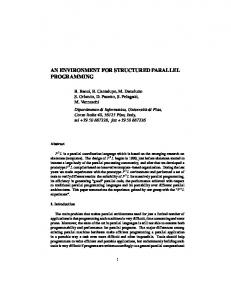
3. ISE Framework ISE is comprised of several entities, each playing a specific role in the exchange of data and timing information required to assess the performance of a parallel system running parallel code. The structure of ISE depends to some degree on how the parallel and distributed system will be modeled. Given the configuration in which the processors will be real HWIL, rather than simulated processors, the structure of ISE is shown in Figure 1.
4
Virtual Prototype Processors
CPU
CPU
CPU
CPU
Process Share File
Relay
Socket
Process Machine Simulation Machine Model Share File API
Processes
Relay
API
API
API
BONeS Network Model
Figure 1. ISE structure with HWIL processors
The process machine is responsible for HWIL execution of the program running in parallel on the various processors in the virtual prototype. The ISE runtime process manager creates a process share file where each process has a column that it uses to read and write information that is passed to and from the model share file during execution. Relay programs on the process machine and simulation machine keep the process and model share files consistent. Each process has a corresponding application programming interface (API) agent within the network model that translates between communication calls and simulated network packets. When a data block is sent from a transmitting process, the data, data size, and destination values are sent to the transmitting API that translates this information for use by the network model. The model dutifully carries the information to the specified destination where it is read by the receiving API, which translates it to the receiving process. For the purposes of relieving the network model of the need to propagate large data blocks, the data is stored in an intermediate location in ISE, and only the address of the data is passed through the network. The performance of the network is unaffected by the actual data values contained in the data block, but it is dependent on the frequency and size of data blocks, and the ISE represents these factors accurately.
3.1 High-fidelity Models In ISE, the network, processor, and software components of the parallel system can be implemented as discreteevent, high-fidelity models of fine granularity that handle the data communications of the parallel application. The models are created using a commercial CAD modeling tool from Alta Group, a division of Cadence, called the Block-Oriented Network Simulator (BONeS) [2, 35] to minimize creation time and maximize model fidelity by using standard library components and simulation management. An additional advantage of using a structured tool
5
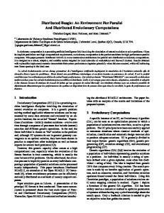
to develop these various models is that the design and measurement techniques of each model remain consistent. Such consistency is important in order to keep the models modular and interoperable, and to allow valid comparisons to be made between models. The BONeS Designer package consists of editors, libraries, and management functions intended to support the development of event-driven network and processor models. The term event-driven refers to simulations that sequentially execute through a dynamic list of events. Simulated time stands still until all events for that time have been completed, at which point events scheduled for the next point in time are started. A diagram of the structure of the BONeS development environment is shown in Figure 2. The Data Structure Editor (DSE) is used for the creation and modification of data structures (e.g. packet formats). The organization and connection of hierarchical process blocks (i.e. the model itself) is accomplished with the Block Diagram Editor (BDE). The Primitive Editor is used to create blocks for use in the BDE from scratch using C++ code. The Simulation Manager controls execution of the model, and any data that was collected during the simulation is viewed with output graphs generated by the Post Processor. The core library contains many elements that are common to network model creation, and consequently, it reduces development and debugging time.
Data Structure Editor (DSE)
Packet Formats
Block Design
Complete Models
Primitive Editor
C++ Code
Core Library Ready-Made Blocks
Block Diagram Editor (BDE)
Simulation Manager (SM)
Results
Post Processor (PP)
Graphs
Figure 2. BONeS modeling and simulation components
A typical network model in BONeS is created directly from a description of the message formats, queue structures, mechanisms, and overall protocol operation. In the case of modeling well-known networks and other interconnects, this description may come straight from the specification standard. Often, the message formats are translated directly into the DSE with a few added fields, such as a time stamp or sequence number, that are used solely for data collection purposes and do not affect the behavior of the protocol being modeled. The queue structures and mechanisms of the protocol are modeled using pre-existing blocks from BONeS libraries, user-
6
defined blocks written with C++ code (with the Primitive Editor shown in Figure 2), or a hierarchical combination of both types of blocks. The transmission speed and propagation delays are accounted for by using delay mechanisms along the network data paths, which causes the simulation clock to increase by an amount determined by the bandwidth and length of the transmission medium. Sample packet types and an internal network node structure are shown below in Figures 3 and 4, respectively. The network chosen for this sample is the Scalable Coherent Interface (SCI) which is explained in more detail in a later example.
Figure 3. Sample packet types in BONeS
Figure 4. Sample network node structure in BONeS
In a traditional network simulation study, the individual network nodes are constructed from the specification, and then multiple nodes are connected together into a scenario with an appropriate topology. The number of nodes is fixed in a given scenario, so multiple scenarios must be created to study the behavior of different network sizes. To drive the models with statistical distribution, synthetic parametric traffic generators are connected to each node. These conventional traffic generators, in conjunction with statistics probes, are typically used to measure average
7
throughput, latency, and other performance characteristics that may be checked with mathematical analysis to validate the overall protocol operation. An illustration of this methodology is given in Figure 5 below. By contrast, in ISE the traffic generators are replaced by API agents that generate and receive real network traffic based on the demands of the external processes.
Traffic Generator
Traffic Generator
Traffic Generator
Traffic Generator
Statistics Probes
Network node
Network node
Network node
Network node
Figure 5. Typical 4-node network simulation scenario with traffic generators
To be compliant with ISE, a network model must support two vital operations. First, since the network is performing real data communication, a field in the data structure must be defined that contains a pointer to the data block location in external memory. Second, the size of the data block must be used properly by the mechanisms that simulate link and propagation delay. The current implementation of ISE has been used over BONeS network models with the configuration shown previously in Figure 1. However, BONeS communication software models can also be included in the ISE’s virtual prototype by simply inserting them between the ISE communication APIs and the nodes of the network model. For example, a model such as that written by Chen, et al. [9] might be used to inject highly accurate TCP or UDP overhead to the simulation. The addition of a processor model to execute code instead of using the HWIL capabilities would require a modification to the configuration in Figure 1. The ISE structure would change to eliminate the process machine, and the runtime process manager would spawn processes directly to the processor models. This modification would simplify the current ISE runtime manager duties but would require the addition of an equivalent operating system, compiler, linker, and assembler and would significantly increase the complexity of the simulation model. Currently, the ISE uses only HWIL processors to execute parallel code segments rather than processor models that mimic the behavior and performance. Given the increasing standardization and use of RISC processor architectures in the field, from workstations to supercomputers, the processors in an ISE virtual prototype can in many cases be realistically simulated by the execution of the processor in the simulation platform itself. By using a HWIL approach in this fashion, the disadvantages of long simulation times and the difficulties of model creation for each kind of processor can be avoided. To accommodate the inclusion of the widest range of possible processors, ISE allows the designer to automatically scale up or down the execution times measured on these HWIL processors to match the requirements of the processors in the virtual prototype. The limit to this scaling philosophy occurs when
8
the architecture of the processor in the target system (e.g. a digital signal processor) is largely different from the RISC processors used in the host workstations. In this case, there has been previous evidence that processor architectures implemented as software models can accurately relate the performance of actual machine language code [17, 18]. The time and effort needed to create such models should be weighed in advance against the expected effect on the final simulation results.
3.2 High-level Parallel API In order to use a high-level parallel coordination language, the application programmer must be provided with a standard library of “black-box” function calls to support the message-passing communication. The behavior of these function calls is defined by a parallel language specification, the exact implementation of which depends upon the underlying network structure. In a conventional parallel API implementation, function procedures are ported to the specific underlying communication network with appropriate optimizations to exploit architectural features. In ISE, the same idea has been used to create an API library for the MPI parallel coordination language [28]; the only significant difference here is that the underlying communications network exists solely within the high-fidelity network models described previously. ISE’s API is built into BONeS blocks and is interfaced with the network model by simple connection paths between corresponding ports on the modules. In addition to defining how the MPI function calls are handled, the API interfaces BONeS to the external environment by creating, reading from, and writing to the share files shown in Figure 1.
Table 1. MPI function calls currently supported by ISE
MPI_Comm_rank
Setup the MPI system and strip MPI-specific command-line options. Retrieve the rank number for the process.
MPI_Comm_size
Retrieve the number of nodes in the MPI system.
MPI_Send MPI_Recv
Send data to another node; returns when the data is accepted by the network. Blocking receive for data from another node.
MPI_Finalize
End the process’s participation in the MPI system.
MPI_Probe
Blocking probe on reception of data from another node.
MPI_Iprobe
Non-blocking check on reception of data from another node.
MPI_Bcast
Send broadcast data to all nodes or receive broadcast data.
MPI_Barrier
Block until all other nodes have arrived at a barrier.
MPI_Wtime
Retrieve the current time.
MPI_Reduce
Participate in a vector reduction operation, such as elementby-element minimum, maximum, sum, product, etc.
MPI_Init
The initial implementation of the ISE interface to MPI is compliant with a subset of the MPI standard. ISE currently supports the key function calls that are necessary to perform the most common communications over MPI. A list of the function calls supported along with their descriptions is provided in Table 1. These functions serve to
9
make ISE a versatile tool by allowing almost any unmodified message-passing parallel program to be interfaced to the virtual prototype.
3.3 Putting It All Together ISE provides several mechanisms by which the hardware models and software applications discussed above are integrated into a single powerful simulation environment. The software-in-the-loop (SWIL) methodology in which the real software is used during simulation provides considerable insight into the intricacies of system development. The hardware-in-the-loop (HWIL) mechanisms used in ISE add realism to the processor portion of the simulations and decrease simulation time. Finally, a profiling interface to ISE simulations gives designers easy access to a graphical performance-monitoring tool. The concept behind SWIL is the ability to use real application software in the simulation. Using such a mechanism results in considerable portability advantages, which was in fact one of the original goals of the MPI coordination language. To use an MPI application over ISE, the user takes the same code that compiles and runs on real parallel and distributed systems with any commercial or freeware MPI implementation. The only difference is that the code is linked with ISE’s version of the MPI library instead of the library for the real parallel system. Movement from simulation to real implementation, or vice versa, can be made without apprehension about modifying the functionality of the software during the move. The HWIL concept is just as integral to ISE as SWIL. Using the processor in the host workstation to execute the user’s application and timing the code blocks with real-world time, ISE is able to include many of the complexities of modern workstations into the simulation as desired. For instance, by timing code blocks using real-world time, ISE results will include the performance effects of system calls and standard library calls from the user’s application. Furthermore, by optionally using a host workstation that is executing one or more competing jobs, the measured code-block times will include the time the SWIL application spends waiting while sharing the processor with the other applications of lesser, equal, or greater priority. Thus, ISE results can reflect the performance of that parallel application in a multi-user environment with deterministic or random activities in competition for system resources. In order to analyze the performance of the virtual prototypes created with ISE, it is often helpful to view all the events in the parallel system using a graphical profiling tool. All simulation runs with ISE automatically capture the necessary timing information to create a log for use with the freely available Upshot profiling program [19]. The sample profile in Figure 6 shows the computation and communication times for a manager/worker parallel decomposition of a matrix multiplication. Each horizontal row of the output corresponds to one processor in the parallel system, and time progresses from left to right. The thin sections of each row represent the computational code blocks executed by the HWIL of ISE. The thick bars are communication calls handled by the network model, with arrows indicating sender-receiver pairs and the legend indicating which particular MPI call (e.g. Send, Recv, Bcast) is occurring. When event durations are too small to view adequately, such as the Send blocks in Figure 6, Upshot is able to zoom in so that the designer can examine portions of the execution more closely. Using this profiling interface, the numerous design choices possible with ISE become more easily quantified and evaluated.
10
Figure 6. A sample of the parallel profiling output in ISE via Upshot
With these mechanisms available to the designer, rapid virtual prototyping of complex parallel and distributed systems becomes possible. Due to the SWIL and HWIL capabilities, the application software created during this process is immediately available for real parallel and distributed systems without the need for any modifications. The interface to BONeS provides the designer with the ability to create high-fidelity network models, the interface to MPI provides access to the most popular message-passing coordination language in use today, and ISE itself provides the glue to make integrated simulation more flexible and realistic than was previously possible.
4. Containment of Simulation Explosion The use of high-fidelity models in the simulative process may become unwieldy due to the amount of time and computing power needed to complete such simulations. Particularly in the case of simulating large distributed systems comprised of detailed models of every component, the simulation time may become such a dominant factor that the user may complain that rapid virtual prototyping is not very rapid. Methods invoked by ISE in order to reduce the necessary computing power and reduce simulation time include distributed simulation techniques and the novel method of fast forwarding. It is also worth mentioning that the use of HWIL processors for execution of the user’s application, in addition to providing more realistic timing results, saves the simulation the burden of a processor model, again helping to contain simulation explosion. There is a whole field dedicated to optimization of simulating large, complex models in a parallel or distributed manner using warping, checkpoints, rollback-recovery, and the like. Many such methods are described in Fujimoto [20] and Righter, et al. [34]. These methods attack the model explosion problem at a fine level of granularity so that multiple CPUs work together to speed up a single simulation based on one set of parameters. However, if the parameters of the simulation are varied, as is often the case, then unique permutations are created that require independent simulations. Therefore, as proposed by Biles, et al. [5] and others, farming these similar yet independent simulations to many loosely coupled workstations in a coarse-grained parallel manner can yield the same speedup as fine-grained methods but with less coordination overhead and complexity.
11
The key to effective distribution of simulations is the use of varied parameters to create enough simulations to keep the workstations busy. Figure 7 illustrates how a large simulation task consisting of several parameter sets may be partitioned at the fine-grained and coarse-grained levels. In this case, suppose that three instances of a network model with bandwidths of 10 Mb/s, 100 Mb/s, and 1 Gb/s are to be studied. Further suppose that each instance requires 1 hour to simulate and that there are 3 workstations available to the simulation environment. With the finegrained approach to simulation parallelism, the first simulation could be executed in parallel on all 3 workstations in 20 minutes. The second simulation would then be spawned, completing in 20 minutes, followed by the third simulation. The result is that all 3 simulations are completed in 1 hour. By contrast, the coarse-grained approach employed by ISE executes the 3 simulations concurrently on the 3 workstations (i.e. one simulation per machine), resulting in all 3 simulations again completing in 1 hour. Although this comparison has been simplified and disregards the effects of overhead and synchronization, these effects would likely lower the efficiency of the finegrained approach more than that of the coarse-grained.
Simulation Time
First Second Third Workstation Workstation Workstation
First Second Third Workstation Workstation Workstation
First 1/3 Hour
10-Mb/s Model
First 1/3 Hour
Second 1/3 Hour
100-Mb/s Model
Second 1/3 Hour
Third 1/3 Hour
1-Gb/s Model
Third 1/3 Hour
Fine-grained parallelism of simulations
10Mb/s Model
100Mb/s Model
1Gb/s Model
Coarse-grained distribution of simulations
Figure 7. Fine-grained parallelism vs. coarse-grained distribution of simulations
ISE is designed to fully exploit BONeS’s ability to spawn multiple concurrent iterations of a single simulation scenario. Each iteration corresponds to a single permutation of a parameter set that occurs when the effect of changing one or more variables is desired. The use of range variables in BONeS causes the simulation manager to spawn the iterations as batch jobs to the available networked workstations selected at simulation time. ISE supports multiple iterations by carefully matching the multiple process iterations on the process machine (see Figure 1) with the corresponding iterations on the simulation machines. Further support is provided by the Upshot profiling interface. ISE creates profiling output for each node of each iteration and allows the user to not only view the results of nodes for a particular iteration, but also multiple sets of results for the same node from different iterations. This capability adds to the usefulness of ISE for comparative analysis of the virtual prototypes. The second method employed by ISE to control simulation explosion is fast forwarding. As is often the case, the specification for the network that is to be used as the network model in ISE may require idle packets or symbols to be continuously sent during periods of network inactivity. A high-fidelity model of such a network will faithfully
12
create, communicate, and sink these idle symbols whenever the transmitting device has no packets to send. Such will be the case during all periods of sequential computation. To simulate the communication of idle symbols during these times may very well be unimportant to the fidelity of the simulation and would only add to simulation explosion. At the user’s request, ISE can fast forward through periods of network inactivity, thus saving considerable simulation time. Without fast forwarding, several seconds of network idle time would require several hours or days to simulate; however, with fast forwarding it will take only seconds. Thus, during these periods, simulation time is on the order of the simulated execution time of the virtual prototype. The two methods of coarse-grained distributed simulation and fast forwarding add significant convenience for the designer, which is often a deciding factor in whether a tool is deemed useful or not. In fact, both these methods were extremely helpful in speeding up the process of collecting results for the comparative case study shown in the next section, which involves the simulation of 32 design permutations on the virtual prototype for a parallel and distributed system.
5. Validation and Case Study As with any new simulation environment, a demonstration of the validity and usefulness of ISE is needed. In this section, a validation of ISE is introduced using SCI experiments. Two validation experiments are described, a network latency experiment for validating communication delays and a parallel computing experiment for validating both communication and computation. The goal for both validation tests is to compare the performance results from ISE to those from a real testbed. Also included in this section is the description of a comparative case study in which two parallel signal-processing algorithms are simulated over distributed architectures with varying network and processor speeds. The results of these experiments are presented in Section 6.
5.1 Description of Validation Experiments Since the primary goal of ISE is to serve as a tool for predicting parallel and distributed system performance, it is desirable to have the results of a simulation closely match that of the real system. In order to validate the models used in ISE, the results of programs run on the real system can be compared to the ISE-simulated system and delay parameters can be set accordingly. The modeled system presented here is based on an SCI network connecting RISC workstations. IEEE Standard 1596-1992 Scalable Coherent Interface [23] is based on a structure of scalable register-insertion rings with shared-memory split transactions. The SCI standard specifies a data rate of 8 Gb/s per link with current implementations from Dolphin Interconnect Solutions, the leading SCI vendor, supporting 1.6 Gb/s. A node diagram in Figure 8 below illustrates the internal node structure of SCI. A request or response packet entering the node on the input link is relayed by the address decoder to the request or response input FIFO, respectively, if the packet’s destination address matches the address of the node. If it does not match, the packet is relayed through the bypass FIFO to return to the network via the output link. Similarly, requests and responses made by the host are queued and then multiplexed onto the output link along with the output of the bypass FIFO. The SCI specification has been implemented in the design of the SCI cards from Dolphin [14], and in the SCI node model we have constructed in BONeS, verified, and integrated into ISE.
13
MUX
bypass FIFO
Response Input FIFO
Request Input FIFO
Response Output FIFO
Request Output FIFO
Host Application Logic
address decode
output link
input link
Figure 8. SCI node model
The two validation experiments are designed to measure the two major types of delays that are incurred within a parallel and distributed system: communication and computation. A high-fidelity model of a network protocol and communications stack is used to simulate and determine the communication time, and the execution of code blocks over a real or simulated processor constitutes the computation time. To validate the communication and computation time reported by ISE, these experiments are run over the SCI cluster, a parallel and distributed computing testbed. This testbed consists of 200-MHz UltraSPARC-2 workstations running Solaris 2.5.1 and interconnected by 1.6 Gb/s SCI. The network interface cards are SCI/Sbus-2B devices from Dolphin, and the MPI implementation used by the programs is MPISCI [31]. Figure 9 illustrates how SCI in the real and ISE-simulated system configurations compare.
MPISCI runtime spawn
MPI Manager Code
MPI Worker Code
Solaris OS
Solaris OS
MPISCI API
MPISCI API
Dolphin SCI Card
Dolphin SCI Card
Workstation #0
Workstation #1
Figure 9a. SCI cluster testbed composed of UltraSPARC workstations connected by SCI adapter cards (2-node case)
14
ISE runtime spawn
MPI Manager Code
MPI Worker Code Solaris OS
BONeS SCI Node
BONeS SCI Node
ISE API
ISE API
Process Share File
Model Share File
Laboratory Operations Network
Laboratory Operations Network
Process Workstation
Simulation Workstation
Figure 9b. Structure of ISE in the simulation of the virtual prototype of the SCI cluster (2-node case)
The first validation experiment, Acknowledged Send, uses MPI calls to send simple, acknowledged packet transfers between computers across the network. This test is used to measure the application-to-application communication latency through the communication software stack and the network itself. The second validation experiment is a Matrix Multiply parallel program written in MPI that produces both communication and computation delays. The manager node in this program distributes parts of two matrices to be multiplied by the worker nodes. The intermediate results from each node are collected by the manager after the calculations.
5.2 Description of Case Study There are many situations in which it is desirable to first validate a parallel system model by ramping down the size or speed of the components to match a testbed in the laboratory. Once the accuracy of the models has been validated and optimized to meet the needs of the design, the virtual prototype can then be ramped back up to the sizes and speeds required of the new system. For example, we may validate the virtual prototype for a candidate parallel system with SCI operating at 1.6 Gb/s using existing hardware. Once the validation is complete, the virtual prototype can then be modified to operate with an 8.0 Gb/s SCI data rate with a high degree of confidence in the results. In this fashion, we can use small testbed prototypes to garner more accuracy for the models, and then move forward with network data rates, processor speeds, degrees of parallelism, and other enhancements that are not easily attained in a testbed prototype due to limitations in technology, cost, component availability, etc. In effect, we leverage the best features of the experimental world with the best of the simulative world. Of course, whether we validate with a small testbed prototype or not, the eventual goal is to design, develop, and evaluate a new parallel and distributed computing system. In so doing, we may wish to hold the architecture fixed, vary the algorithms, and study the effects. In other cases, we may wish to hold the algorithms fixed, vary the architectural features, and study these effects. Or, in still other cases, our intent may be to study a wide array of permutations in both algorithm and architecture. To illustrate the latter, a case study is presented in which two parallel algorithms for sonar signal processing are compared while changing features of the distributed computer
15
architecture model. This case study is intended to demonstrate that ISE is useful as an interactive and iterative design environment for architectures which may not have as yet a real-world implementation. The case study involves the development of a virtual prototype for a special-purpose parallel and distributed system targeted for high-speed and low-power execution of sonar beamforming algorithms. The architecture of interest is a multicomputer comprised of eight independent processors interconnected by a bidirectional, linear array network and communicating via message passing. The link speed between the nodes is varied between 2.5 Mb/s and 10 Mb/s, and the processor speed on each network node is varied between 25% and 100% of the performance of an UltraSPARC microprocessor. Two parallel algorithms coded and implemented in MPI, called Beamformer1 and Beamformer2, are compared to evaluate their relative performance and sensitivity to network and processor speed. The two programs differ in that Beamformer1 focuses on parallel beamforming whereas Beamformer2 goes one step further by adding overlap of computation and communication wherever possible. As such, the processor and network speeds will affect the two programs in different ways, making ISE the ideal environment to prototype the system and evaluate the design alternatives.
6. Results The results of the networking and parallel processing experiments for validation purposes are provided in the following subsection. Afterwards, the case study on performance issues with embedded parallel architectures and algorithms for sonar signal processing using variation in algorithms and architectural features is presented.
6.1 Results of Validation Experiments The results of the first set of validation tests, Acknowledged Send, over a 2-node SCI network connecting UltraSPARC workstations are shown in Figure 10a. The data points of the two curves represent values collected from the same MPI program run over the actual testbed and the ISE-simulated virtual prototype. The values of parameters in the network and communication stack models have been calibrated, and this tuning coupled with the inherent accuracy of the high-fidelity model developed for SCI allows us to achieve performance curves that are nearly identical. Since the model was adjusted for two nodes, it can reasonably be expected that the results will be somewhat dissimilar for different network sizes. To preserve the validity of the simulations, all model parameters adjusted in the 2-node simulations were held constant for the 4-node simulations. The 4-node test results shown in Figure 10b begin to deviate as the packet size increases. At 65536-integer packets, there is a maximum of 20% deviation between real and simulated Acknowledged Send times.
16
12
Execution Time (ms)
10
8 ISE Testbed
6
4
2
0 512
1024
2048
4096
8192 16384 32768 65536
Size of Packets Sent (in 4-byte integers)
Figure 10a. Testbed vs. ISE: Acknowledged Send experiments for 2-node SCI clusters
35
Execution Time (ms)
30 25 20
ISE Testbed
15 10 5 0 512
1024
2048
4096
8192 16384 32768 65536
Size of Packets Sent (in 4-byte integers)
Figure 10b. Testbed vs. ISE: Acknowledged Send experiments for 4-node SCI clusters
The results of the execution times from the second set of validation experiments are shown in Figure 11. Figure 11a presents the results of the 2-node parallel Matrix Multiply over both the testbed and the ISE-simulated virtual prototype, while Figure 11b shows the results for a 4-node run. Simulation parameters for these experiments were unchanged from the validated parameters set for the Acknowledge Send tests.
17
250
Execution Time (ms)
200
150 ISE Testbed 100
50
0 32
48
64
80
96
112
128
144
Dimension of Square Matrices (with 4-byte integer elements)
Figure 11a. Testbed vs. ISE: Matrix Multiply completion time for 2-node SCI clusters
140
Execution Time (ms)
120 100 80
ISE Testbed
60 40 20 0 32
48
64
80
96
112
128
144
Dimension of Square Matrices (with 4-byte integer elements)
Figure 11b. Testbed vs. ISE: Matrix Multiply completion time for 4-node SCI clusters
As these results illustrate, ISE provides performance estimation that closely matches the performance of the SCIconnected UltraSPARC testbed, thus giving the user a high degree of confidence in the validity of the virtual prototype. However, when no validation testbed is available, ISE is still strong at allowing comparative tradeoffs to be made with respect to algorithm and architecture design parameters.
18
6.2 Results of Case Study The results from the comparative case study of the parallel beamformer algorithms over simulated architectures of varying network and processor speeds are presented next. The graph in Figure 12a shows the behavior of the Beamformer1 algorithm running over the virtual sonar system prototype. To vary the speed of the eight processors in the virtual prototype of the sonar computer system, variations in processor speed range from 25% to 100% of the performance of an UltraSPARC processor running at 170 MHz. Similarly, variations in network speed range from 2.5 to 10 Mb/s. The results of Beamformer2, shown in Figure 12b, provide the comparative information that makes this case sensitivity study most useful. At each point on the two contour graphs, a comparison of the overall execution time for each algorithm can be reliably made because the network model assumptions and processor behavior have been kept constant between algorithms. The only differences between the two figures are the algorithms themselves. The advantages of the overlapping communication in Beamformer2 are reflected in the fact that the performance is relatively insensitive to network speed in most cases, whereas in Beamformer1 the slower network speeds have a marked effect on performance. With both algorithms the processor speed was found to contribute significantly to overall performance in a non-linear fashion. The sort of sensitivity and comparative analysis shown here is a major advantage when using ISE for rapid virtual prototyping of complex systems. Tradeoff analyses can be made to better understand the contributions of each potential bottleneck in the architecture or software. ISE supports an interactive and iterative process in which the designer can quickly make changes to address key performance issues. Such a methodology leads to more efficient and effective design solutions. In addition, virtual prototyping with ISE allows the designer to keep multiple candidates (e.g. the two versions of the beamformer above or two candidate networks) on hand for further evaluation at a moment’s notice.
0.05 Execution Time (seconds)
0.045 0.04 0.035 0.03 0.025 0.02 0.015 0.01 0.005 0 2.5
5
Network Speed (Mb/s)
7.5
0.5 10
0.75 1
0.25 Processor Speed (fraction of an UltraSPARC)
Figure 12a. Simulated execution time for Beamformer1 with variance in network and processor speeds
19
0.05
Execution Time (seconds)
0.045 0.04 0.035 0.03 0.025 0.02 0.015 0.01 0.005 0 2.5
5
Network Speed (Mb/s)
7.5
0.5 10
0.75 1
0.25 Processor Speed (fraction of an UltraSPARC)
Figure 12b. Simulated execution time for Beamformer2 with variance in network and processor speeds
6. Conclusions This paper has given an overview of the structure, features, and intended uses of the Integrated Simulation Environment. This environment allows the user to execute real parallel programs running on virtual prototypes of parallel and distributed computing architectures and systems, by leveraging HWIL processors and high-fidelity models, so as to evaluate overall system performance. While high fidelity brings with it an increase in computational complexity for simulation, methods have been presented by which the problem of simulation explosion can be contained. Validation results for both networking and parallel processing behavior have illustrated how a virtual prototype in ISE can achieve virtually the same performance as the actual target system. The usefulness and flexibility of ISE for developing and comparing notional network architectures, with real parallel code instead of simple traffic generators, has also been demonstrated with a case study taken from a real-world application in sonar signal processing. ISE provides the designers of parallel and distributed architectures and algorithms a method to combine highfidelity network models and real parallel code running over real processors for execution-driven simulation. Moreover, the models may be tuned with small-scale prototypes from the testbed and then ramped up to larger data rates, processor speeds, degrees of parallelism, etc. so that results from ISE can nearly emulate the behavior of the target system. ISE is equally useful in comparing notional architecture models with consistent assumptions and performance trends that mimic the expected behavior of the real systems. Models that have been created and validated in BONeS by hardware architects may be shared with software designers who can better analyze how their programs will perform on the architecture. Likewise, software can be provided to the hardware designers, who can tailor the architectures for optimum performance.
20
Several future extensions to ISE are under development in order to make it an even more powerful approach for the design and analysis of parallel and distributed systems. For example, future work will strive to extend the capability of simulating fully heterogeneous systems composed of different kinds of processors (e.g. RISC, VLIW, DSP), connected by a variety of networks in complex topologies, with an assortment of interfaces, memory hierarchies, etc. In addition, work will be pursued toward the goal of making the interface to processor models as seamless as is the current interface to the HWIL processors. With these enhancements, the usefulness of ISE will be expanded to cover a wider range of system designs, from scalable multicomputer systems with multiple network connections to tightly coupled, shared-memory multiprocessors.
Acknowledgments The support provided by the Office of Naval Research on grant N00014-98-1-0188 is acknowledged and appreciated, as is the SCI equipment support from Dolphin Interconnect Solutions, Inc.
References [1] J.K. Adams, D.E. Thomas, “Design Automation for Mixed Hardware-Software Systems,” Electronic Design, vol 45, n 5, Mar. 3, 1997, pp. 64-72. [2] Alta Group, BONeS DESIGNER User’s Guide, Foster City, CA: Alta Group, 1994. [3] T.E. Anderson, D.E. Culler, D.A. Patterson, “A Case for NOW (Networks of Workstations),” IEEE Micro, vol 15, n 1, Feb. 1995, pp. 54-64. [4] D. Becker, R.K. Singh, S.G. Tell, “An Engineering Environment for Hardware/Software Co-Simulation,” 29th ACM/IEEE Design Automation Conference, 1992, pp. 129-134. [5] W.E. Biles, C.M. Daniels, T.J. O’Donnell, “Statistical Considerations in Simulation on a Network of Microcomputers,” Proceedings of the 1985 Winter Simulation Conference, 1985, pp. 388-393. [6] W.D. Bishop, W.M. Loucks, “A Heterogeneous Environment for Hardware/Software Cosimulation,” Proceedings of the IEEE Annual Simulation Symposium, 1997, pp. 14-22. [7] M. Borgatti, R. Rambaldi, G. Gori, R. Guerrieri, “A Smoothly Upgradable Approach to Virtual Emulation of HW/SW Systems,” Proceedings of the International Workshop on Rapid System Prototyping, 1996, pp. 83-88. [8] E.A. Brewer, C.N. Dellarocas, “PROTEUS: A High-Performance Parallel-Architecture Simulator,” Performance Evaluation Review, vol 20, n 1, Jun. 1992, pp. 247-248. [9] J. Chen, M. Lee, T. Saadawi, “A Block-based Simulation Tool for the Enhancement of TCP/UDP Protocols,” Simulation, vol 64, n 1, Jan. 1995, pp. 61-63. [10] K. Cosic, I. Kopriva, I. Miller, “Workstation for Integrated System Design and Development,” Simulation, vol 58, n 3, Mar. 1992, pp. 152-162. [11] F. Dahlgren, “A Program-Driven Simulation Model of an MIMD Multiprocessor,” Proceedings of the 24th Annual Simulation Symposium, 1991, pp. 40-49. [12] H. Davis, S.R. Goldschmidt, J. Hennessy, “Multiprocessor Simulation and Tracing Using Tango,” Proceedings of the International Conference on Parallel Processing, vol 2, 1991, pp. II99-II107. [13] T. Delaitre, G.R. Ribeiro-Justo, F. Spies, S.C. Winter, “A Graphical Toolset for Simulation Modeling of Parallel Systems,” Parallel Computing, vol 22, no 3, Feb. 28, 1997, pp. 1823-1836. [14] Dolphin Interconnect Solutions, AS, Dolphin SBUS-2 Cluster Adapter Card Overview, Oslo, Norway: Dolphin Interconnect Solutions, Sep. 1996. [15] D. Dunlop, K. McKinley, “OMIA Standard Model Interface for IP Delivery,” Proceedings of the International Verilog HDL Conference, Mar. 1997, pp. 83-90. [16] G. Edwards, R. Sankar, “Modeling and Simulation of Networks Using CSIM,” Simulation, vol 58, n 2, Feb. 1992, pp. 131-136. [17] A. George, “Simulating Microprocessor-Based Parallel Computers Using Processor Libraries,” Simulation, vol 60, n 2, Feb. 1993, pp. 129-134. [18] A. George, S. Cook, “Distributed Simulation of Parallel DSP Architectures on Workstation Clusters,” Simulation, vol 67, n 2, Aug. 1996, pp. 94-105.
21
[19] W. Gropp, E. Lusk, N. Doss, A. Skjellum, “A High-performance, Portable Implementation of the MPI Message Passing Interface Standard,” Parallel Computing, vol 22, n 6, Sep. 1996, pp. 789-828. [20] R.M. Fujimoto, “Parallel Discrete Event Simulation,” Communications of the ACM, vol 33, n 10, Oct. 1990, pp. 30-53. [21] T.V. Huynh, H.G. Tirud, “An Approach to End-to-End System Simulation,” 1997 IEEE Aerospace Conference Proceedings, 1997, pp. 447-461. [22] IEEE, 1499-1998 IEEE Draft Standard D4.0: Interface for Hardware Description Models of Electronic Components, Piscataway, NJ: IEEE Service Center, 1998. [23] IEEE, 1596-1992 IEEE Standard for Scalable Coherent Interface (SCI), Piscataway, NJ: IEEE Service Center, 1993. [24] M. Kasbekar, S. Nagar, A. Sivasubramaniam, “pSNOW: A Tool to Evaluate Architectural Issues for NOW Environments,” Proceedings of the International Conference on Supercomputing, 1997, pp. 100-107. [25] K. Kim, Y. Kim, Y. Shin, K. Choi, “An Integrated Hardware-Software Cosimulation Environment with Automated Interface Generation,” Proceedings of the International Workshop on Rapid System Prototyping, 1996, pp. 66-71. [26] T. Le, F.-M. Renner, M. Glesner, “Hardware in-the-loop Simulationa Rapid Prototyping Approach for Designing Mechatronics Systems,” Proceedings of the International Workshop on Rapid System Prototyping, 1997, pp. 116-121. [27] C. Liem, F. Naçabal, C. Valderrama, P. Paulin, A. Jerraya, “System-on-a-Chip Cosimulation and Compilation,” IEEE Design & Test of Computers, vol 14, n 2, Apr.-Jun. 1997, pp. 16-25. [28] Message-Passing Interface Forum, MPI: A Message-Passing Interface Standard, Knoxville, TN: U. of Tennessee, May 1994. [29] C.M. Pancake, M.L. Simmons, J.C. Yan, “Performance Evaluation Tools for Parallel and Distributed Systems,” IEEE Computer, vol 28, n 11, Nov. 1995, pp. 16-19. [30] D.K. Panda, D. Basak, D. Dai, R. Kesavan, R. Sivaram, M. Banikazemi, V. Moorthy, “Simulation of Modern Parallel Systems,” Proceedings of the 1997 Winter Simulation Conference, 1997, pp. 1013-1020. [31] Parallab, “Programmer’s Guide to MPI for Dolphin’s SBus-to-SCI Adapters,” Bergen, Norway: Parallab, U. of Bergen, 1995. [32] D. Park, R.H. Saavedra, “Trojan: A High-Performance Simulator for Shared Memory Architectures,” Proceedings of the 29th Annual Simulation Symposium, 1996, pp. 44-53. [33] S.K. Reinhardt, M.D. Hill, J.R. Larus, A.R. Lebeck, J.C. Lewis, D.A. Wood, “The Wisconsin Wind Tunnel: Virtual Prototyping of Parallel Computers,” Performance Evaluation Review, vol 21, n 1, Jun. 1993, pp. 48-60. [34] R. Righter, J.C. Walrand, “Distributed Simulation of Discrete Event Systems,” Proceedings of the IEEE, vol 77, n 1, Jan. 1989, pp. 99-113. [35] K.S. Shanmugan, V. Frost, W. LaRue, “A Block-Oriented Network Simulator (BONeS),” Simulation, vol 58, n 2, Feb. 1992, pp. 83-94. [36] A. Sivasubramaniam, “Execution-Driven Simulators for Parallel Systems Design,” Proceedings of the 1997 Winter Simulation Conference, 1997, pp. 1021-1028. [37] J.-P. Soininen, T. Huttunen, K. Tiensyrjä, H. Heusala, “Cosimulation of Real-Time Control Systems,” Proceedings, European Design Automation Conference with EURO-VHDL, 1995, pp. 170-175. [38] C.A. Valderrama, F. Naçabal, P. Paulin, A.A. Jerraya, “Automatic Generation of Interfaces for Distributed CVHDL Cosimulation of Embedded Systems: An Industrial Experience,” Proceedings of the International Workshop on Rapid System Prototyping, 1996, pp. 72-77. [39] J. Wilson, “A New Methodology for Co-Design: Virtual System Integration,” Electronic Engineering, vol 67, n 825, Sep. 1995, pp. S55-S59.
22