May 3, 2007 - Frequency Division Multiplex (OFDM) and Code Division ... The power spectral density (PSD) should ... the PSD mask imposed by the FCC.
An OFDM-CDMA scheme for High Data Rate UWB applications arXiv:0705.0428v1 [physics.comp-ph] 3 May 2007
Emeric Gu´eguen, Matthieu Crussi`ere, Jean-Franc¸ois H´elard Electronics and Telecommunications Institute of Rennes IETR/INSA, 20 Av. des Buttes de Co¨esmes 35043 Rennes Cedex, France {emeric.gueguen, matthieu.crussiere, jean-francois.helard}@insa-rennes.fr
Abstract— In this paper, we investigate a new waveform for UWB systems obtained by the combination of Orthogonal Frequency Division Multiplex (OFDM) and Code Division Multiple Access (CDMA). The proposed system, called Spread Spectrum - Multi-Carrier - Multiple Access (SS-MC-MA) turns out to be a judicious solution to combat frequency selectivity and narrowband interferers, and to manage the coexistence of several users and piconets. It is shown that the addition of a degree of freedom brought by the spreading component of SS-MC-MA allows to optimize jointly the assignment of the number of used codes and coding rates in order to make the system more robust. Through simulations, it is demonstrated that the new system can outperform Multi-Band OFDM Alliance (MBOA) for low data rates and is able to provide wider range of rates. Index Terms— UWB, MB-OFDM, MC-CDMA, SS-MC-MA.
I. I NTRODUCTION Ultra Wide Band (UWB) radio systems are today acknowledged as high potential solutions for Wireless Personal Area Networks (WPAN). The novelty of these systems lies in the possibility of non regulated access to the spectral resource leading to a flexible use of the radio channel for an important number of applications. In 2002, the Federal Communications Commission (FCC) regulated UWB systems by imposing a spectral mask to limit the transmission power [1]. According to the FCC regulation, a signal must have a minimum bandwidth of 500 MHz or a bandwidth to central frequency ratio above 0.2 to be considered as UWB. The power spectral density (PSD) should also not exceed -41.3 dBm/MHz. The UWB channel, running from 3.1 to 10.6 GHz, is frequency selective and considered as almost invariant in time. Proposed UWB systems must not disturb existing narrowband systems, such as Wireless Local Area Network (WLAN) 802.11a standard at 5 GHz for example. Following that, the Institute of Electrical and Electronics Engineers (IEEE) initiated a standardization process, referred to as task group 802.15.3a, to define a high data rate physical layer for WPAN. The last three years have hereby seen the emergence and the confrontation of two approaches: a pulse radio solution using Direct Sequence - Code Division Multiple Access (DS-CDMA) ternary codes supported by UWB Forum, and a multi-carrier multi-band solution based on Orthogonal Frequency Division Multiplex (OFDM). The latter has been
proposed by the Multi-Band OFDM Alliance (MBOA) consortium and is currently promoted by the main actors of the general public and component industries [2]. In section II, this paper presents the main parameters of the MBOA solution. After a critical analysis of this solution section III the interest of adding a CDMA component to the MB-OFDM waveform. In section IV, the principle of the new waveform called Spread Spectrum - Multi-Carrier - Multiple Access (SS-MC-MA) is presented. Particularly, SS-MC-MA offers for the future WPAN good performance and great flexibility for the resource allocation between users of a same piconet. This new UWB system is then described in section V and the comparison of the performances obtained with the MBOA solution and the SS-MC-MA system is presented in section VI. Finally, section VII concludes the paper. II. T HE MBOA
SOLUTION
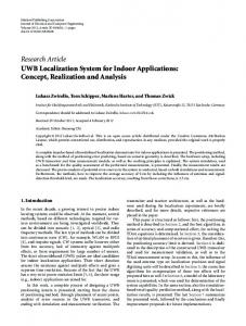
The MBOA consortium proposes to divide the available band into 14 sub-bands of 528 MHz, as illustrated in Fig. 1. Each of these sub-bands allows the transmission of an OFDM signal, obtained from a 128-point Inverse Fast Fourier Transform (IFFT). Most of the UWB studies focus on the first mode which clusters the first three sub-bands from 3.1 to 4.8 GHz. The multi-user management within a piconet is based on Time Division Multiple Access (TDMA) by using a Time-Frequency Code (TFC). At a given moment, each user then occupies one of the three sub-bands of mode 1 [2]. The signal, sampled during the analog-to-digital conversion, has a limited bandwidth of 500 MHz, leading to low-cost components and power consumption reduction. However, the use of TFC translates into frequency hopping from one subband to another at each OFDM symbol. Hence, each user benefits from the frequency diversity brought by the three sub-bands in mode 1. In addition, considering that each user occupies a given sub-band only one third of the time, it is possible to optimize the transmitted power while respecting the PSD mask imposed by the FCC. Lastly, it is also advised to plan the cohabitation of 4 piconets in a same environment. Transmitted data rates in each sub-band essentially depend on the coding rate, as the modulation applied to the different subcarriers of the OFDM multiplex is a quadrature phaseshift keying (QPSK). Data rates, from 53.3 to 480 Mbit/s, are listed in Table I. For certain modes, each complex symbol
Mode 1
Mode 2
Mode 3
Mode 4
Mode 5
Lc subcarriers
Band Band Band Band Band Band Band Band Band Band Band Band Band Band 1 2 4 5 6 7 8 10 11 12 13 14 3 9
3432 3960
4488
5016
Fig. 1.
5544
6072 6600 7128
7656 8184 8712
9240 9768 10296
f (MHz)
Channels distribution for MBOA solution
53.3 80 110 160 200 320 400 480
Modulation
QPSK QPSK QPSK QPSK QPSK QPSK QPSK QPSK
Coding rate (R) 1/3 1/2 11/32 1/2 5/8 1/2 5/8 3/4
MC-CDMA system with Lc = Np
Nu user = P codes
TABLE I MBOA DATA RATES Data rate (Mbit/s)
SS-MC-MA system
P codes of one user
Conjugate symmetric input to IFFT
Time spreading factor (TSF)
Coded bits per OFDM symbol
Yes Yes No No No No No No
2 2 2 2 2 1 1 1
100 100 200 200 200 200 200 200
and its conjugate symmetric are transmitted into the same OFDM symbol by one subcarrier and its ”mirror” subcarrier respectively. This way, the frequency diversity is exploited into each sub-band at the cost of a division by 2 of the useful transmitted data rate. Moreover, for modes corresponding to data rates from 53.3 Mbit/s to 200 Mbit/s, a time spreading of 2 is applied. It consists in the transmission of the same information during 2 consecutive OFDM symbols in order to take advantage of a better frequency diversity, due to the joint application of the TFC. All OFDM parameters of the MBOA solution are detailed in [2]. One of the main difference compared to a classical OFDM system is the use of a zero padding (ZP) guard interval instead of the traditional cyclic prefix (CP). Indeed, CP is replaced by trailing zeros. Details of this operation are well explained in [3]. ZP allows one to obtain a spectrum with fewer ripples in the useful band than with a traditional CP. Thus the signal can take the exact shape of the PSD mask [2]. To summarize, the MBOA solution offers some advantages for high data rate UWB applications, such as the signal robustness against the channel selectivity and the efficient exploitation of the signal energy received within the prefix duration. The main argument of multi-carrier modulation in general is often quoted in favour of the MBOA solution, when one compares it with the competitive DS-CDMA solution. The latter can actually hardly make use of all the received energy, the number of the RAKE fingers being compulsorily limited for complexity reasons. However, the MBOA solution is relatively limited in a multi-user and multi-piconet context. Particularly, when the only three first sub-bands of the first mode are considered, conflicts immediately appear at the addition of a fourth user within a piconet, whereas scenarios going
user Nu user 2 user 1
frequency
Np subcarriers
Fig. 2. Data distribution of different users for MC-CDMA and SS-MC-MA systems
up to 6 simultaneous users have classically to be considered. III. T HE CDMA
COMPONENT ADD INTEREST
Recent studies have proposed to add a CDMA component to the MBOA solution in order to improve the system robustness or the resource sharing between several users [4]. This spreading component essentially allows to organize the access of several users to a common resource. Taking into account the UWB channel characteristics, frequency selectivity and slow time variations in indoor environment, spreading is generally performed along the frequency axis, leading to a Multi CarrierCDMA (MC-CDMA) waveform. The symbols of all users are transmitted by all the subcarriers as depicted in Fig. 2, the spreading code length Lc being lower or equal to the subcarrier number Np of the OFDM multiplex. Compared to the ”traditional” MBOA solution, and beyond a greater facility in the resource sharing, the MC-CDMA system also presents a better robustness against channel frequency selectivity ([4], [5]) and improves the UWB signal robustness against narrowband interferences. This last point is fundamental for uncontrolled access to the spectral resource. In [4] however, authors suggest to use an MC-CDMA signal with a bandwidth Bw = 1.58 GHz, equivalent to 3 sub-bands of the MBOA signal, which leads to an highly increase of the sampling frequency of the analog-to-digital conversion. IV. A
NEW WAVEFORM FOR MULTI - BAND
UWB :
THE
SS-MC-MA By applying a spreading code and a multi-access component, we propose in this paper an SS-MC-MA waveform [6], which is new for UWB applications and offers better performance and more flexibility in the resource management. A. SS-MC-MA principle SS-MC-MA can be viewed as a multi-block system compared to the classical MC-CDMA system, since the spectrum is divided into ”blocks” of several subcarriers. The SS-MCMA solution, illustrated in Fig. 2, consists in assigning to each
user a specific set of subcarriers according to a Frequency Division Multiple Access (FDMA) approach. Code dimension Lc can then be exploited for an adaptive resource optimization and sharing (modulation type, data rate, . . . ). Spreading in the frequency domain leads to diversity gain and, as it is the case of MC-CDMA, improves the signal robustness against narrowband interferers. With an SS-MC-MA signal, symbols are transmitted simultaneously on a specific subset of subcarriers by the same user and undergo the same distortions. Self-interference (SI) which then replaces the Multiple Access Interference (MAI) obtained with MC-CDMA signals, can be easily compensated for by mono-user detection with only one complex coefficient per subcarrier.
Input data
Scrambler
Convolutional Encoder
Bit Interleaver
Puncturer
Mapping
Spreading (FHT)
Insertion pilots and guard sub-carriers
OFDM Modulation + Add Zero Padding (ZP)
Channel
Output data
De-Scrambler
Fig. 3.
Viterbi Decoder
De-Puncturer
Detection + Despreading (IFHT)
Bit De-Interleaver
Remove pilots and guard sub-carriers
Overlap & Add + OFDM Demodulation
MBOA transmission chain (SS-MC-MA in broken lines)
B. Signals expression In the MBOA solution case, the signal generated at the output of the IFFT expresses:
B. SS-MC-MA advantages Let us consider the case of the MBOA standard in mode 1 (Fig. 1). 1) Case of three or less users: The SS-MC-MA system allows the allocation of a 528 MHz sub-band for each user. This system offers the same performance and advantages as MC-CDMA to which a simplicity is added for the channel estimation in reception. In fact, with SS-MC-MA a given subcarrier is distorted by only one channel, the one of the user associated with this subcarrier. At contrary, with an MCCDMA system, each subcarrier is corrupted by the different channels of different users, which increases considerably channel estimation complexity. In that case, each user has to estimate the response of many channels all over the total available bandwidth. 2) Case of more than three users: In the MBOA solution, conflicts appear from 4 users and could cause information losses. In the SS-MC-MA case, the code dimension could be exploited to share a same 528 MHz sub-band between 2 or even 3 users if necessary. In that case, the generated signal within a given block corresponds to an MC-CDMA signal, but with a limited number of users per block (2 or even 3). More generally, in a multi-piconet context, the possibility of easily modifying the number of spreading codes assigned to a given user in a given piconet, allows the SS-MC-MA scheme to offer a more flexible and efficient dynamic resource sharing than the MBOA solution does. V. T HE NEW UWB SYSTEM
SOFDM (t) =
+∞ P
n=+N PST /2
×e
(1)
j2πn∆F (t−iTCP )
where ∆F , NST and TCP represent the subcarriers spacing, the total number of used subcarriers and the spacing between two consecutive OFDM symbols, respectively. Xn (i) is a complex symbol belonging to a QPSK constellation and is transmitted by subcarrier n during the ith OFDM symbol. It represents a data, a pilot or a reference symbol. pc (t) is a rectangular window defined by: pc (t) =
�
1 0
0 ≤ t ≤ TFFT TFFT ≤ t ≤ TFFT + TCP + TGI
(2)
In the SS-MC-MA case, complex symbols are converted into P parallel symbols Dl (i) (with P ≤ Lc ) which are transmitted by the same Lc subcarriers. P then represents the load, and is namely equal to Lc in the full load case and to Lc /2 in the half load case. The waveform is the same as previously, but the complex symbol Xm (i) which is transmitted by the mth subcarrier (m varying from 1 to Lc = 16, with m = n modulo(16)) of a block of Lc = 16 subcarriers bound by the same spreading codes of length Lc can be express by: Xm (i) =
P X
Dl (i)cl,m
(3)
l=1
A. System studied The proposed system is based on the MBOA solution. Fig. 3 introduces the MBOA transmission chain in continuous lines and, in dashed lines, the functions that are added to obtain an SS-MC-MA waveform. These functions are mainly the Hadamard Transform (”Fast Hadamard Transform”: FHT) at the transmitter and the inverse transform (IFHT) at the receiver. In addition, Minimum Mean Square Error (MMSE) single user detection is applied. The spreading factor Lc is chosen equal to 16 and the number of useful subcarriers is reduced from 100 to 6 × 16 = 96 for each OFDM symbol. This means that 4 more guard subcarriers are added.
Xn (i)pc (t − iTCP )
i=−∞ n=−NST /2
where Cl = [cl,1 ... cl,m ... cl,L ] is the lth Walsh-Hadamard orthogonal spreading code and Dl (i) represents the P complex symbols, belonging to a QPSK constellation and which are transmitted by the block of Lc subcarriers considered during OFDM symbol i. In reception, as in the classical OFDM system case, mono-user detection is simply realized at the output of the FFT by one complex multiplication per subcarrier. MMSE detection technique is considered leading to coefficients: gn,i =
h∗n,i 2
|hn,i | +
1 γn,i
(4)
TABLE II
TABLE III
C HARACTERISTICS OF WIDEBAND CHANNELS CMi
P OSSIBLE D ATA R ATES WITH SS-MC-MA
Mean excess delay (ns): τm RMS delay spread : τrms Distance (m) LOS/NLOS
CM1
CM2
CM3
CM4
10.38 8.03