efficient hardware, software and engineering environment to be used for each. Also ..... work order scheduling, including materials requirement management.
An open automation architecture for flexible manufacturing Georg Neugschwandtner, Maarten Reekmans, Dirk van der Linden University of Antwerp, Faculty of Applied Engineering Salesianenlaan 30, 2660 Hoboken Belgium {georg.neugschwandtner, maarten.reekmans, dirk.vanderlinden}@uantwerpen.be
Abstract Being able to respond flexibly to business opportunities is essential for the manufacturing industries to stay competitive. Making flexible use of the plant floor equipment is an essential aspect to this. The research presented proposes an approach to automation systems design and implementation, focusing on (but not limited to) batch processes and derived from the ISA-88 standard, with the aim of minimising the programming effort required for a new product by following a modular approach. Particular attention is given to implementing the interfaces between system modules in an open manner using the OPC UA communication standard.
1. Introduction In the manufacturing industries, constantly seeking ways to improve the ratio of return on investment in a factory is essential for staying competitive. Flexible automation systems enable an enterprise to produce closer to demand, with less waste. Quick reconfigurability allows “working the process equipment harder”, making better use of the investment made. Another angle of approach is to reduce the fixed cost for obtaining a plant with a given capability and flexibility. In the context of automation systems, this translates to reducing expenses for hardware, software and configuration (programming). In order to reduce these expenses, having the ability to choose the best-value components and contractors for individual parts of the overall system is essential. To gain this ability, clearly defined interfaces between these parts are necessary. Open, standardized interface definitions are an essential enabler in this domain. They also reduce the effort for system integration, allowing contractors to offer their services at lower cost.
2. Concept The goal of the concept presented in the following is to separate the task of automating a manufacturing plant into sub-tasks in a way which allows the most suitable and
efficient hardware, software and engineering environment to be used for each. Also, it intends to decouple the components implementing these sub-tasks from each other as far as possible to minimize mutual impact in case of updates. This supports efficient, “mix-and-match” creation and quick reconfiguration of the overall system and improves its maintainability. The structure shown is not only intended as a guideline on how to organise functionality in automation devices at design-time, but also as the basis for how a device can make this functionality visible and accessible via a communication network in a standardized, vendorindependent way. Being able to dynamically browse the functionality available on a device is a significant step towards a self-documenting, consistent overall system. The element types which are defined correspond to the kind of available interactions. They focus on flexible, distributed process control starting at the sensor/actuator level. Part 1 of the ISA-88 standard [3] already fulfils a significant part of these goals. However, ISA-88 does not cover communication interfaces at the level we are targeting. The model described below is in large parts patterned on ISA-88, but seeks to extract a small, readily understandable, generalized set of element types (and make additional definitions) relevant to those interfaces. While it is – just as ISA-88 – expected to have the most benefit when automating batch processes, it is intended to be applicable to manufacturing automation in general. 2.1. Model We propose describing the process (or manufacturing) equipment by a tree hierarchy of entities connected via is-part-of relationships. In Figure 1, these equipment entities (EE) are shown as rectangles. This structure is used to organize elements representing automation functionality: their place in the hierarchy identifies which part of the equipment they handle. Higher-level elements use the services of the elements below them. The leaves are formed by encapsulations of instruments and final control elements (sensors and actuators); e.g., a temperature sensor, or a heating element. Above them, representations of automatic control functionality which keep associated equipment in a single desired state can be
Figure 1. Equipment entities and control elements placed. A prime example would be an on-off or PID control loop (involving the temperature sensor and the heating element), governed by the set value. The interactions possible with these kinds of elements largely revolve around a single datapoint (a present or desired value). Therefore, they are in the following referred to as datapoint oriented control elements (DOE). This notwithstanding, the state information which DOE expose related to their purpose in the process may also be composite (e.g., for a motorized valve: 60% open; currently opening). In addition, DOE can optionally provide various ancillary functions related to this datapoint: They can be switched to a manual override mode where the datapoint value is manually supplied for purposes of testing (simulation), fault detection and situations during production which require manual control of the process. This manual mode is activated in a common way for all DOE. Low-level permissives or interlocks, equipment fault checks and alarm generation (e.g., on reaching low or high limits) are also handled at the level of DOE. Building on the datapoint oriented elements, action sequence control elements (ASE) represent automatic control functionality which takes the process equipment through a sequence of states. ASE are always associated with an EE. An example would be a sequence which waits for a heated vessel to reach a specified temperature (by modifying the temperature controller setpoint and monitoring the temperature sensor value via the DOE) and then holds it for a specified time. In [9], this kind of task is referred to as “process oriented control”, with the tasks performed by DOE in contrast being referred to as “equipment oriented control.” ASE represent manipulations on the manufactured product (or its base materials or preliminary stages). They follow a sequence of steps linked by condition-guarded transitions. Parameters can be supplied to an ASE to modify the actions taken for each execution, and the ASE
can report data collected during its execution. The interface of an ASE exposes whether the step sequence associated with the ASE is currently being executed or not, as well as a number of further transitional and exceptional states. Transitions between states can be triggered by the sequence completing successfully, an operator intervention or an equipment fault. This state machine is the same for all ASE. Optionally, the ASE can expose the steps and transitions, indicating the currently active step. In this case, the element can also allow control of its execution mode: besides automatic execution, it can be set to require additional operator approval for each transition, or step actions may be selected entirely manually. ASE can exist at multiple levels in the equipment hierarchy in order to allow the complexity of process control to be managed by way of successive abstractions: complex control procedures can be assembled from elementary actions. As an example, Figure 2 shows the “Ferment” ASE making use of the “Transfer In” ASE. An ASE has the exclusive right to command the execution state of ASE below it in the hierarchy. This includes the responsibility to coordinate them, for example for the use of shared equipment or a material transfer. At higher hierarchy levels, such coordination can form the major part of an ASE’s logic. These commands may not “skip over” control elements at intermediate levels (strict layering); however, not every EE must be associated with an DOE or ASE. If multiple ASE are associated with the same EE, only one of them can execute at the same time. With regard to commanding the execution state of elements, note that transitions can only be requested; the lower-level element decides if the action is safe to take and which “housekeeping” activities have to be completed before actually making the transition. The execution state of lower-level elements is therefore a typical transition guard condition. 2.2. Application An automation system following the model described will be implemented on a number of networked devices, each of which will implement one or more DOE or ASE. The hierarchical equipment structure is shared by all devices to identify the functionality they provide. Elements at each hierarchy level must be uniquely named so that each element is uniquely identified by its full path name. The stipulations on control element interaction made above still hold. Therefore, all ASE associated with one EE will usually be managed by the same control device to keep the necessary synchronization activities local. A typical setup would consist of a PC based manufacturing control system addressing the top of the hierarchy and focusing on coordination tasks and PLCs (programmable logic controllers) handling one of the remaining sub-trees each and providing dependable elementary actions. Depending on their tasks and target audience (process engineers vs. control engineers), the manufacturing control system and the PLCs can use specialized engineering tools, programming paradigms and software
well as applications such as the recipe designer can profit from the ability to browse the PLCs to see which equipment entities they control and which control elements are available for interaction.
3. Relevant standards and related work
Figure 2. Element mapping and abstraction environments. As a case in point, flexible batch control revolves around recipes – complex control procedures specific to a product. The process engineer would use a recipe designer application based on ISA-88 Procedure Function Charts [4] to, for example, create the “Ferment” high-level ASE as shown in the right half of Figure 2. At this level, the “Transfer In” lower-level ASE is used as a black box. No low-level control systems programming is required to create a new recipe. When the recipe is run, the high-level ASE is executed by the batch manufacturing control system, invoking the low-level ASE – which is implemented on a PLC – via its network interface. In addition to assembling recipes from elementary actions, batch control systems must, among other things, also provide a way to define which production related data are collected during the run of a recipe, and store these batch records. They must also be able to manage multiple recipes and to scale a recipe to the batch size which is to be produced. Again, IT systems are a more convenient platform for these tasks than PLCs, which are in turn excellently suited for real-time control and process I/O. The distribution of functionality between the PLCs and the manufacturing control system depends on the application domain. For batch processing, the manufacturing control system would assume a high amount of procedural sequence logic to ensure optimum flexibility in running the process. For machine control, sequence logic will largely be handled by the PLC due to the more complex and time-critical elementary actions. Still, the machine can be represented by an ASE, allowing its execution to be started, stopped, or manually controlled. For example, a batch process and its attached packing line can be controlled in a uniform manner this way. Figure 2 also shows how a HMI (human machine interface) would interact with the DOE to give an operator control over the process equipment. Such an HMI can include all PLCs in the system and also provide alarm handling, giving it the a role closer to a SCADA (supervisory control and data acquisition) system. Likewise, HMI functions would be provided to interact with ASE. The HMI as
Various aspects of flexible automation, from mechanical engineering to the integration of enterprise IT and automation, have long been the focus of research and development. For example, Hodek and Floerchinger [7] improve flexibility by setting up discrete production as a sequence of autonomic production modules which are parameterized by information stored on the product. Sauter [8] reviews integration issues within the automation system, between automation and enterprise systems, and between lifecycle phases. As previously mentioned, the model proposed in the previous section is largely derived from Part 1 of the ISA-88 standard (IEC 61512), which defines terminology and object models for batch control applications. It is also inspired by Brandl’s commentary on ISA-88 [5]. However, it goes beyond ISA-88 by considering the application of this standard to the implementation of selfdescribing communication interfaces between model element instances. An ISA-88 based batch automation system typically uses a PC based recipe execution engine for the higherlevel elements of the procedural control model, while embedded controllers execute the lower-level elements. The link between these levels is typically known as a phase logic interface (PLI, cf. e.g., [5]). However, while ISA88 implicitly makes some requirements on such a PLI (it must support interaction with the execution state machine of the lower-level element), no further implementation or protocol details are defined. As a consequence, PLIs today are proprietary to each batch automation system brand. Likewise, the scope of ISA-88 does not include, for example, the question whether browsing the steps of a procedural control element should be an option. ISA-88 places more emphasis on modelling the batch process itself. It provides a hierarchy of model elements with fixed levels and semantics particular to each level, which is very valuable as a reference frame for discussing a batch automation project. The model discussed in this paper, however, is focused on the requirements of communication interfaces for modular automation. Therefore, it generalises the fixed hierarchy of the relevant ISA-88 models into a recursive structure. This keeps the model lean and emphasizes its general applicability by removing batch oriented terminology. Roughly, the hierarchy of EE corresponds to the ISA-88 physical model (process cell, unit, equipment module, control module), the ASE correspond to the ISA-88 procedural control model (procedures, unit procedures, operations, phases), and DOE correspond to the control functionality associated with ISA88 control modules.
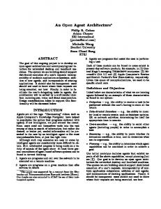
To validate the flexible design concept described previously and demonstrate its applicability to batch and discrete processes, a prototype system was implemented on a lab-scale version of a soft drink production plant with three work centres: A production station that allows batches of liquid to be mixed, agitated, heated, cooled and transferred, a bottling station, and a palletizing station. As shown in Figure 3, each of the work centres is controlled by its own PLC. Two different brands of PLCs are used to accentuate vendor independence. The production station’s automation software contains a total of 12 DOE encapsulating the hardware (e.g., sensors and valves) and 14 ASE implementing low-level operations (e.g., transfer in, mix, heat). Building on these low-level ASE and coordinating them, the PC-based Production Execution System (PES) offers a layer of higher level ASE, which can be used in recipes. In the prototype, the mapping between high and low level ASE is static. Two versions of the PES
Mobile recipe designer (Android) ISA-95 based MOM
Process control Operator supervision using off-the-shelf visualization package Custom-developed operator supervision
(HMI/SCADA)
Production Execution System (Java) Production Execution System (ST) (PC-based)
OPC UA
4. Implementation
Recipe management
OPC UA
As a communication protocol, the OPC Unified Architecture (UA) standard [2] (also to be published as IEC 62541) appears well suited. It is widely adopted in industry and addresses key requirements of the interfaces required in the context of this paper. OPC UA provides robust data transport and extensive information modelling capabilities, including type hierarchies and inheritance. OPC UA servers provide clients with a browsable address space containing data and meta-data (such as type definitions). Various data types and higher-level services such as alarm generation and historizing of data are standardized. Many of them can immediately be leveraged in our architecture (for example, to cover the alarm handling aspect of DOE). In addition, custom information models can be defined. A first design of an OPC UA information model representing the execution state machine of an ISA-88 control module is presented in [9]. Ideally, OPC UA information models are based on established standards from other domains. A relevant specification in this context is the companion standard related to IEC 61131-3 (PLCopen) [1]. IEC 61131-3 standardizes the structure and language of PLC programs; the companion standard standardizes the mapping of such a program (its configuration and variables) to the OPC UA server address space, enabling a vendor-neutral representation of data structures. Gˆırbea et al. [6] demonstrate an example OPC UA address space of a discrete flexible manufacturing system, focused on exposing the inner structure of the PLC program based on the object types from PLCopen companion standard and custom object types. Virta et al. [10] explore the use of OPC UA for interaction between an ISA-88 based process control system and a manufacturing execution system based on the ISA-95 standard, using OPC UA to transfer recipes and lists of scheduled and completed batches.
OPC UA
PLC Vendor 1
Batch Process Cell
OPC UA
PLC Vendor 2
OPC UA
Bottling Line
PLC Vendor 2
Palletizer
Figure 3. System architecture have been developed: a Java based one, and a PES written in IEC 61131-3 Structured Text (ST) using the control systems development environment of a project partner. Likewise, two alternate recipe management applications were developed. The first is a stand-alone recipe designer. This Android mobile application allows a user to easily assemble a recipe by drag and drop of ASE blocks using a touch user interface and send it to the PES for execution. The second application was contributed by a project partner using their ISA-95 based Manufacturing Operations Management (MOM) solution. In addition to a recipe designer and manager, it also contains functionality work order scheduling, including materials requirement management. While ISA-95 was designed to standardise interactions between MOM and Enterprise Resource Planning (ERP) systems, its data model also applies well to the requirements of this project. ASE are represented by Process Segments/Operations Segments, assembled into Operations Definitions, and associated with Operations Requests for execution. For operator interaction with the manufacturing system, a custom HMI component was developed that allows the operator to monitor the process (visualization, alarms) and to intervene if necessary (supervisory control). An alternate HMI panel was designed using an off-the-shelf HMI design suite. 4.1. Open information exchange All key components in the prototype are accessible through open, well defined OPC UA interfaces. This makes it straightforward for any OPC UA client to interact with them, enabling the system to be built from bestof-breed components. To emphasise this advantage in our prototype, alternate versions of several components were made that can replace the original ones without reconfiguring any other component, giving the system an additional degree of flexibility. In the prototype, the OPC UA data model covers: • The DOE in the system with their current state and the ability to override the controls by using manual mode for each element (equipment model)
• The ASE with common control commands (start, stop, hold, ...) and current state (idle, running, complete, ...), plus individual control parameters and report parameters for each element (procedural model) • A model to transfer simple sequential recipes and access the recipe structure containing all the steps and associated parameters To coordinate the work centres (e.g., when a filled bottle should be picked up by the palletizing station), information must be exchanged between them. The relevant signals in the available setup have relaxed timing requirements, so a special real-time capable fieldbus is not needed and OPC UA is used. All PLCs in the prototype provide embedded OPC UA servers and clients. By using existing standards, we were able to create an architecture where components can exchange information and cooperate on an abstract level. To facilitate PLC programming, an ISA-88 framework was developed in Structured Text which handles the states and modes of each ISA-88 module and procedural element and defines the interface between these components. The internal structures of the modules, including those defining interfaces (such as the ASE control state machine) are exposed consistently through OPC UA as long as the PLC vendor adheres to the IEC 61131-3 for OPC UA companion specification. In the prototype, we take advantage of this to enable the use of complex custom types within the limits of the embedded OPC UA servers.
5. Conclusion and outlook The architecture proposed in this paper supports the creation of flexible manufacturing automation systems where sub-tasks are assigned to components in a way to separate concerns and support change. For example, a PLC should only handle elementary control operations that have to be executed in a particularly stable and timely manner to prevent loss or damage, while other manufacturing control procedures can be configured via a more high-level toolset which does not require PLC engineering skills. Loose coupling between sub-tasks and components also enables parts of the system to be updated without affecting other parts more than necessary. The architecture leverages accepted standards, in particular OPC UA, to enable a vendor-neutral and open design. While it is aligned with the ISA-88 standard, it is not limited to batch automation. With open, standardized communication interfaces in use, a system following this architecture can be comprised of control devices, engineering tools and HMI from different manufacturers. By way of its open design, advanced features such as self-documentation are easily achieved: for example, if PLC code is updated, the corresponding higher-level operation will immediately be available for inclusion in a batch recipe, and the HMI will be able to display and single-step through the individual actions if necessary.
To achieve this, the next step will be to further extend and refine the interface definitions. Our goal is to keep them aligned with ISA-88 Part 1 and Part 2 while maintaining the advantages of our generic, recursive structure. The execution control state machine interface will be of particular interest, also due to its potential role as a PLI. Another main goal will be to extend the representation of action sequences in the address space and the capabilities of the PES to support parallel steps and the nesting of action sequence control elements. Other useful extensions would be support for data collection from the process (e.g., batch reports) and leveraging the OPC UA companion standard for ISA-95 to provide access to DOE data (e.g., pump operation hours via the ISA-95 role based equipment model), taking another step toward the “manufacturing service cloud.”
6. Acknowledgment This work was funded by the Flemish Agency for Innovation by Science and Technology in the context of the IMA project (grant number TETRA 110131). The authors would like to thank the involved project partners and motivated students for their significant efforts towards implementing the prototype.
References [1] OPC UA Information Model for IEC 61131-3, Release 1.00. PLCopen and OPC Foundation, 2010. [2] OPC Unified Architecture Specification, Release 1.02. OPC Foundation, 2012-2013. [3] ANSI/ISA-88.00.01. Batch Control Part 1: Models and Terminology. ISA, 2010. [4] ANSI/ISA-88.00.02. Batch Control Part 2: Data Structures and Guidelines for Languages. ISA, 2001. [5] D. Brandl. Design patterns for flexible manufacturing. ISA, 2007. [6] A. Gˆırbea, S. Nechifor, F. Sisak, and L. Perniu. Design and implementation of an OLE for process control unified architecture aggregating server for a group of flexible manufacturing systems. IET Software, 5(4):406–414, 2011. [7] S. Hodek and F. Floerchinger. An approach for modular production from mechanics to decentralized control, realized in the SmartFactoryKL . In Proc. 14th IEEE Intl. Conf. on Emerging Technologies and Factory Automation (ETFA’2009), 2009. [8] T. Sauter. Integration aspects in automation - a technology survey. In Proc. 10th IEEE Intl. Conf. on Emerging Technologies and Factory Automation (ETFA’2005), volume 2, pages 255–263, 2005. [9] D. van der Linden, H. Mannaert, W. Kastner, V. Vanderputten, H. Peremans, and J. Verelst. An OPC UA interface for an evolvable ISA88 control module. In Proc. 16th IEEE Intl. Conf. on Emerging Technologies and Factory Automation (ETFA’2011), 2011. [10] J. Virta, I. Seilonen, A. Tuomi, and K. Koskinen. SOAbased integration for batch process management with OPC UA and ISA-88/95. In Proc. 15th IEEE Intl. Conf. on Emerging Technologies and Factory Automation (ETFA’2010), 2010.