Multi-channel Cognitive Radio Networks. Vamsi Krishna Tumuluru, Ping Wang, and Dusit Niyato. Center for Multimedia and Network Technology (CeMNeT).
An Opportunistic Spectrum Scheduling Scheme for Multi-channel Cognitive Radio Networks Vamsi Krishna Tumuluru, Ping Wang, and Dusit Niyato Center for Multimedia and Network Technology (CeMNeT) School of Computer Engineering, Nanyang Technological University, Singapore. Abstract—In this paper, we develop an opportunistic spectrum scheduling scheme for cognitive radio networks. In the proposed scheme, the channel status (i.e., whether being occupied by primary users) and the instantaneous channel quality (SNR at the secondary receiver) are assumed to vary fast within a frame which consists of a fixed number of slots. At each scheduling epoch, each secondary user will observe the channel conditions, namely the channel status and the channel quality. Based on the queue size and the observed channel conditions, each secondary user will estimate the throughput for each channel over the frame to be scheduled. A scheduling algorithm is performed to maximize the expected aggregate throughput of all the secondary users. We evaluate the performance of the proposed scheduling scheme in terms of throughput and percentage of packet drop.
links to connect the secondary users1 with one another. Within a frame, a distributed scheduling algorithm is implemented to activate the available links without causing interference among the users. In [4], several scheduling algorithms which maximize the transmission capacity while keeping fairness among the users were presented. These scheduling algorithms consider the link capacity, signal to interference and noise ratio (SINR), and traffic demand of the users. In [5], scheduling algorithms which consider the interference, fading and packet delay were presented. The objective of the scheduling algorithms in [5] is to maximize the transmission capacity of the users. In [6], scheduling algorithms using ILP were proposed. The scheduling algorithms in [6] consider the packet delay, maximum frequency, interference temperature, and throughput. In all the above works, the conditions of the licensed channels such as primary user activity and channel quality (signal-to-noise ratio measured at the secondary receiver) are assumed to remain constant during the entire frame. Hence, the above schemes are not applicable when these channel conditions vary fast within a frame, say on a slot-by-slot basis. In other words, a slot-based scheduling such as [7] is required when the channel conditions vary on a slot-by-slot basis. However, slot-based scheduling incurs large scheduling overhead over a frame compared to frame-based scheduling. The above schemes work on the principle that a higher throughput is achieved if more bandwidth (channels) is allocated to that user. Such an approach can result in bandwidth wastage if a user which does not have sufficient packets in the queue during the frame is allocated a large bandwidth. Therefore, we consider the queue status of the users in our proposed scheme. In this paper, we develop a queue-aware frame-based opportunistic spectrum scheduling scheme. The objective of the proposed scheduling scheme is to allocate the channels to the users such that the overall throughput is maximized while keeping a low scheduling overhead per frame. A user uses its queue status to calculate its expected throughput over a channel in a frame. Based on the expected throughput, the scheduler assigns the channels to the users with the highest expected throughput.
Keywords – Cognitive radio, opportunistic spectrum scheduling, queuing analysis, spectrum utilization. I. I NTRODUCTION The report published by the Federal Communications Commission (FCC) [1] showed that under the present spectrum allocation framework, the licensed spectrum is underutilized for most of the time while the unlicensed spectrum is heavily occupied. Due to insufficient bandwidth and high interference in the unlicensed spectrum (e.g., 2.4GHz band), the unlicensed wireless networks have often found it difficult to achieve the desired quality-of-service (QoS). To improve the overall spectrum utilization and QoS support, cognitive radio (CR) technology has emerged to allow the unlicensed users (also called secondary users) to opportunistically access the channels allocated to the licensed users (also called primary users) on a non-interfering basis [2]. In most cognitive radio networks, a licensed spectrum usually consists of several channels which can be specified by their center frequency and bandwidth, and the secondary users logically divide the licensed channels into slots. In most cognitive radio networks (CRNs), the secondary user transmissions are conducted over a large time scale called a frame which is composed of a fixed number of slots. Within a frame, the secondary users sense the licensed channels at the beginning of each slot and access the idle channels for the remaining slot duration. An important issue in a CRN is to schedule the data transmission of each secondary user to improve the spectrum utilization and guarantee QoS (e.g. higher throughput, smaller packet delay, etc.) for secondary users. Several spectrum scheduling schemes are available in the literature [3]-[6]. In [3], a MAC layer scheduling algorithm was presented using integer linear programming (ILP). The licensed channels act as
II. S YSTEM M ODEL AND A SSUMPTIONS We consider a CRN consisting of 𝑉 users which can communicate with one another using one of the 𝑈 channels. A scheduling algorithm (explained later) is implemented by
1
1 In the rest of the paper, the term ’licensed channel’ is simply referred as ’channel’. Similarly the term ’secondary user’ is simply referred as ’user’.
the central scheduler (CS) which assigns the channels to the users. We consider time slot based transmission in which one frame is composed of 𝑁 slots. We assume a common control channel is available to the users of the CRN. Such scheduling schemes with a common control channel can also be found in [2] and [6]. In the proposed scheme, the users and the central scheduler exchange control information which includes throughput estimation and transmission schedules. At the beginning of each frame, each secondary user obtains the following information: the status of the channels (from channel sensing), the channel quality of each channel (depending on the received signal power at the destination node), and the queue status of the user. Based on this information2 , each user estimates its expected throughput on each channel during the entire frame. The expected frame throughput is estimated through a Markov chain formulation described in Section III-A. Once the expected throughput for the frame for all the channels is calculated, the user sends a control packet to the CS containing the user index, channel index, and its corresponding expected frame throughput for the channel. Based on the information provided by all the contending users, the CS implements the scheduling algorithm (described in Section III-B) and broadcasts the scheduling information to all the users. When a channel is allocated to a user, the user can transmit data on that channel during the whole frame time. However, in order not to interrupt the transmission of primary users, before transmitting data packets, the user senses the channel at the beginning of each slot. If the primary user activity is not detected, the channel is assumed to be idle for that slot and therefore available for user to access. Let each user have a single transmission queue of size 𝑄 packets. We assume that packet arrivals occur independently for each user and follow a batch Bernoulli process with a mean arrival rate of 𝜆 ∑ packets per slot. The arrival rate 𝜆 can 𝐿 be expressed as 𝜆 = 𝑙=0 𝑙 ⋅ 𝑃 (𝐴 = 𝑙), where 𝑃 (𝐴 = 𝑙) represents the probability of 𝑙 packet arrivals in a slot and 𝐿 denotes the maximum number of packet arrivals. The status of a channel can be either busy or idle depending on the presence or absence of the primary user’s activity. The channel status in slot 𝑛 is denoted by 𝑠𝑛 . 𝑠𝑛 takes the value 0 or 1 depending on whether the channel status is busy or idle, respectively. Similar to [7], the status of a channel is modeled as a two-state Markov chain with the state transition matrix P(𝑠𝑛+1 ∣𝑠𝑛 ) given by ( ) 𝑃 (0∣0) 𝑃 (1∣0) P(𝑠𝑛+1 ∣𝑠𝑛 ) = (1) 𝑃 (0∣1) 𝑃 (1∣1)
a Nakagami-𝑚 distribution [8]. The transmitting users adapt their modulation and coding to cope with the time varying SNR. According to [8], for a given target packet error rate (PER) and average SNR 𝛾, the instantaneous SNR 𝛾 𝑢,𝑣 for a channel 𝑢[ corresponding to user 𝑣 can be partitioned into 𝑢,𝑣 ) 𝐶 regions 𝛾𝑐𝑢,𝑣 , 𝛾𝑐+1 (𝑐 ∈ {0, 1, ⋅ ⋅ ⋅ , 𝐶 − 1}), and within each region a mode corresponding to a specific modulation and coding rate is chosen. Each SNR region is denoted by mode 𝑐𝑢,𝑣 ∈ {0, 1, . . . , 𝐶 − 1}. The SNR region [𝛾0𝑢,𝑣 , 𝛾1𝑢,𝑣 ) corresponds to the mode 𝑐𝑢,𝑣 = 0 in which the transmission is not allowed. [8] provides a procedure to model the fading channel quality as a finite state Markov chain (FSMC) with 𝐶 states. 𝑢,𝑣 The state transition matrix is denoted by P(𝑐𝑢,𝑣 𝑛+1 ∣𝑐𝑛 ) for 𝑢,𝑣 ′ 𝑢,𝑣 every channel 𝑢 associated with user 𝑣. 𝑃 (𝑐𝑛+1 = 𝑗 ∣𝑐𝑛 = 𝑗) denotes the probability that the channel state changes from mode 𝑗 in slot 𝑛 to mode 𝑗 ′ in slot 𝑛 + 1. The transmission rate of a channel 𝑢 in slot 𝑛 is equal to 𝑏𝑛 𝑐𝑢,𝑣 𝑛 where 𝑏𝑛 is a parameter specified based on system requirements. It is worthy to notice that the FSMC model characterizes the channel state transition of secondary users under the condition that the channel is not occupied by the primary users. When primary user is active, secondary users are prohibited to transmit. III. T HE Q UEUE - AWARE O PPORTUNISTIC S PECTRUM S CHEDULING S CHEME In this section, we present the queue-aware frame-based opportunistic spectrum scheduling scheme which is used by the CS for channel allocation. A. Throughput Estimation Let 𝑇𝑛 (𝑢, 𝑣) denote the estimated throughput of user 𝑣 on channel 𝑢 at slot 𝑛 in a frame. We introduce a state vector 𝑢 𝑢,𝑣 𝑣 x𝑢,𝑣 𝑛 = [𝑠𝑛 , 𝑐𝑛 , 𝑞𝑛 ] (𝑛 = 1, 2, . . . , 𝑁 ) for the system, where 𝑢 𝑠𝑛 represents the status (i.e., busy or idle) of channel 𝑢 at slot 𝑛 in a frame3 , 𝑐𝑢,𝑣 𝑛 represents the mode of the channel quality for the channel 𝑢 for user 𝑣 at slot 𝑛, 𝑞𝑛𝑣 represents the queue status of user 𝑣 at the beginning of slot 𝑛, and 𝑁 is the number of slots in a frame. For simplicity of presentation, the state vector for any channel-user pair is indicated as x𝑛 = [𝑠𝑛 , 𝑐𝑛 , 𝑞𝑛 ]. The evolution of the state vector x𝑛 within a frame is modeled using a discrete time Markov chain (DTMC). The probability distribution for the state vector x𝑛 in slot 𝑛 is denoted by Π𝑛 = [Π(𝑠𝑛 =𝑖,𝑐𝑛 =𝑗,𝑞𝑛 =𝑘) ],
for 𝑖 ∈ {0, 1}, 𝑗 ∈ {0, 1, . . . , 𝐶 − 1}, and 𝑘 ∈ {0, 1, . . . , 𝑄}, where Π(𝑠𝑛 =𝑖,𝑐𝑛 =𝑗,𝑞𝑛 =𝑘) represents the probability that the values of states 𝑠𝑛 , 𝑐𝑛 and 𝑞𝑛 are 𝑖, 𝑗, and 𝑘, respectively. A state transition occurs at the end of every slot with a probability 𝑃 (x𝑛+1 ∣x𝑛 ), also denoted as 𝑃 (𝑠𝑛+1 = 𝑖′ , 𝑐𝑛+1 = 𝑗 ′ , 𝑞𝑛+1 = 𝑘 ′ ∣𝑠𝑛 = 𝑖, 𝑐𝑛 = 𝑗, 𝑞𝑛 = 𝑘) where 𝑖, 𝑖′ ∈ {0, 1}, 𝑗, 𝑗 ′ ∈ {0, 1, . . . , 𝐶 − 1} and 𝑘, 𝑘 ′ ∈ {0, 1, . . . , 𝑄}. The state transition matrix P(x𝑛+1 ∣x𝑛 ) for the DTMC is given
where 𝑃 (𝑖′ ∣𝑖)(𝑖, 𝑖′ ∈ {0, 1}) represents the transition probability from state 𝑖 in the current slot to state 𝑖′ in the next slot, and it is assumed to be known to the secondary users as in [7]. With 𝑈 channels, let P(𝑠𝑢𝑛+1 ∣𝑠𝑢𝑛 ) denote the state transition matrix corresponding to channel 𝑢 for 𝑢 ∈ {1, . . . , 𝑈 }. The signal-to-noise ratio (SNR) for the channels measured at destination users are assumed to be time varying, following 2 Note this information corresponds to the first slot in the frame. Such information in the remaining slots of the frame is not known.
(2)
2
3 Note that the channel status in slot 𝑛 is the same for all the secondary users.
by P(x𝑛+1 ∣x𝑛 ) = ⎛ 𝑃(0,0,0∣0,0,0) ⎜ 𝑃(0,0,0∣0,0,1) ⎜ ⎜ .. ⎝ .
𝑃(0,0,1∣0,0,0) 𝑃(0,0,1∣0,0,1) .. .
⋅⋅⋅ ⋅⋅⋅ .. .
𝑃(1,𝐶−1,𝑄∣0,0,0) 𝑃(1,𝐶−1,𝑄∣0,0,1) .. .
𝑃(0,0,0∣1,𝐶−1,𝑄)
𝑃(0,0,1∣1,𝐶−1,𝑄)
⋅⋅⋅
𝑃(1,𝐶−1,𝑄∣1,𝐶−1,𝑄) (3)
⎞ ⎟ ⎟ ⎟ ⎠
Note that some of the arrived packets will be dropped if the queue is full (e.g., 𝑘 ′ = 𝑄). The expected throughput 𝑇𝑛 (𝑢, 𝑣) for any channel-user pair (for presentation simplicity, we denote it as 𝑇𝑛 in the rest of the paper) can be calculated as follows. The state vector for the first slot in the frame is denoted as x1 = [𝑠1 , 𝑐1 , 𝑞1 ]. According to the proposed scheduling scheme, the value of this state vector is obtained from the observation of the channel and queue status at the beginning of each frame. Let 𝑠′ , 𝑐′ and 𝑞 ′ denote the observed values for the channel status, channel mode and initial queue status, respectively. The corresponding probability distribution is denoted by Π1 = [Π(𝑠1 =𝑖,𝑐1 =𝑗,𝑞1 =𝑘) ], (8)
where the transition probability 𝑃(𝑖′ ,𝑗 ′ ,𝑘′ ∣𝑖,𝑗,𝑘) is calculated as follows: 𝑃(𝑖′ ,𝑗 ′ ,𝑘′ ∣𝑖,𝑗,𝑘) = 𝑃 (𝑠𝑛+1 = 𝑖′ , 𝑐𝑛+1 = 𝑗 ′ , 𝑞𝑛+1 = 𝑘 ′ ∣𝑠𝑛 = 𝑖, 𝑐𝑛 = 𝑗, 𝑞𝑛 = 𝑘) 𝑃 (𝑠𝑛+1 = 𝑖′ , 𝑐𝑛+1 = 𝑗 ′ , 𝑞𝑛+1 = 𝑘 ′ , 𝑠𝑛 = 𝑖, 𝑐𝑛 = 𝑗, 𝑞𝑛 = 𝑘) = 𝑃 (𝑠𝑛 = 𝑖, 𝑐𝑛 = 𝑗, 𝑞𝑛 = 𝑘) 𝑃 (𝑞𝑛+1 = 𝑘 ′ ∣𝑠𝑛 = 𝑖, 𝑐𝑛 = 𝑗, 𝑞𝑛 = 𝑘, 𝑠𝑛+1 = 𝑖′ , 𝑐𝑛+1 = 𝑗 ′ ) = 𝑃 (𝑠𝑛 = 𝑖, 𝑐𝑛 = 𝑗, 𝑞𝑛 = 𝑘) ⋅ 𝑃 (𝑠𝑛 = 𝑖, 𝑐𝑛 = 𝑗, 𝑞𝑛 = 𝑘, 𝑠𝑛+1 = 𝑖′ , 𝑐𝑛+1 = 𝑗 ′ ) = 𝑃 (𝑞𝑛+1 = 𝑘 ′ ∣𝑠𝑛 = 𝑖, 𝑐𝑛 = 𝑗, 𝑞𝑛 = 𝑘, 𝑠𝑛+1 = 𝑖′ , 𝑐𝑛+1 = 𝑗 ′ ) ⋅ 𝑃 (𝑠𝑛+1 = 𝑖′ , 𝑐𝑛+1 = 𝑗 ′ ∣𝑠𝑛 = 𝑖, 𝑐𝑛 = 𝑗, 𝑞𝑛 = 𝑘). (4)
for 𝑖 ∈ {0, 1}, 𝑗 ∈ {0, 1, . . . , 𝐶 − 1}, and 𝑘 ∈ {0, 1, . . . , 𝑄} where Π(𝑠1 =𝑖,𝑐1 =𝑗,𝑞1 =𝑘) is given by { 1 𝑖 = 𝑠′ , 𝑗 = 𝑐′ , 𝑘 = 𝑞 ′ (9) Π(𝑠1 =𝑖,𝑐1 =𝑗,𝑞1 =𝑘) = 0 otherwise.
In (4) the state variables 𝑠𝑛+1 , 𝑐𝑛+1 and 𝑞𝑛+1 are independent of one another. Further, 𝑠𝑛+1 does not depend on 𝑞𝑛 and 𝑐𝑛 , similarly 𝑐𝑛+1 does not depend on 𝑞𝑛 and 𝑠𝑛 . Therefore (4) can be expressed as
The probability distribution of the state vector for the remaining slots in the frame is found recursively using the expression 𝑛 [ ∏ ] Π𝑛+1 =Π𝑛 P(x𝑛+1 ∣x𝑛 ) = Π1 P(x𝑛′ +1 ∣x𝑛′ )
𝑃(𝑖′ ,𝑗 ′ ,𝑘′ ∣𝑖,𝑗,𝑘) = 𝑃 (𝑞𝑛+1 = 𝑘 ′ ∣𝑠𝑛 = 𝑖, 𝑐𝑛 = 𝑗, 𝑞𝑛 = 𝑘) ⋅𝑃 (𝑠𝑛+1 = 𝑖′ ∣𝑠𝑛 = 𝑖)⋅𝑃 (𝑐𝑛+1 = 𝑗 ′ ∣𝑐𝑛 = 𝑗) . (5)
=Π1
In (5), the value of 𝑃 (𝑠𝑛+1 = 𝑖′ ∣𝑠𝑛 = 𝑖) is obtained from (1) and the value of 𝑃 (𝑐𝑛+1 = 𝑗 ′ ∣𝑐𝑛 = 𝑗) is obtained from the FSMC model for the corresponding channel-user pair. The conditional probability 𝑃 (𝑞𝑛+1 = 𝑘 ′ ∣𝑠𝑛 = 𝑖, 𝑐𝑛 = 𝑗, 𝑞𝑛 = 𝑘) is calculated as follows. The queue status 𝑞𝑛+1 at the beginning of slot 𝑛 + 1 for any user can be expressed as 𝑞𝑛+1 = 𝑞𝑛 − 𝑑𝑛 + 𝑎𝑛
=Π1
𝑛 [ ∏
𝑛′ =1
][ ]𝑛 [ ]𝑛 P(𝑞𝑛′ +1 ∣𝑞𝑛′ ) P(𝑐2 ∣𝑐1 ) P(𝑠2 ∣𝑠1 ) ] P(𝑞𝑛′ +1 ∣𝑞𝑛′ ) P(𝑐𝑛+1 ∣𝑐1 )P(𝑠𝑛+1 ∣𝑠1 )
𝑛′ =1
(10) for 𝑛 = {1, 2, . . . , 𝑁 − 1}. The expected throughput 𝑇𝑛 in slot 𝑛 (𝑛 ∈ {1, 2, . . . , 𝑁 }) is calculated as ∑ 𝑇𝑛 = Π(𝑠𝑛 =𝑖,𝑐𝑛 =𝑗,𝑞𝑛 =𝑘) ⋅ min(𝑞𝑛 = 𝑘, 𝑏𝑛 𝑖𝑗) (11)
(6)
𝑖,𝑗,𝑘
where 𝑖 ∈ {0, 1}, 𝑗 ∈ {0, 1, . . . , 𝐶 −1} and 𝑘 ∈ {0, 1, . . . , 𝑄}. The expected throughput for the entire frame 𝑇𝑓 (𝑢, 𝑣) (or simply 𝑇𝑓 ) for any channel-user pair is given by
(7)
In (7), 𝑏𝑛 represents the number of packets that can be transmitted in a slot for the lowest transmission mode (𝑐𝑛 = 1). Note that in our proposed scheduling scheme, a portion of the first slot in a frame is used for control information exchange. Therefore, the value of 𝑏1 is different from those in other slots. It depends on the effective transmission time in the first slot after scheduling. From (6) and (7), we have 𝑎𝑛 = 𝑘 ′ − 𝑘 + min(𝑘, 𝑏𝑛 𝑖𝑗), then the conditional probability 𝑃 (𝑞𝑛+1 = 𝑘 ′ ∣𝑠𝑛 = 𝑖, 𝑐𝑛 = 𝑗, 𝑞𝑛 =
𝑛 [ ∏ 𝑛′ =1
where 𝑎𝑛 represents number of packets arriving at the queue in slot 𝑛 whereas 𝑑𝑛 represents the number of packet departures in slot 𝑛. The number of packet departures are calculated from 𝑑𝑛 = min(𝑞𝑛 , 𝑏𝑛 𝑠𝑛 𝑐𝑛 ) .
𝑘) is obtained as ⎧ 𝑃 (𝐴 = 𝑎𝑛 ) if 𝑘 ′ < 𝑄, 0 ≤ 𝑎𝑛 ≤ 𝐿 ⎨ ∑ ′ 𝐿 ′ 𝑎′𝑛 =𝑎𝑛 𝑃 (𝐴 = 𝑎𝑛 ) if 𝑘 = 𝑄, 0 ≤ 𝑎𝑛 ≤ 𝐿 ⎩ 0 otherwise.
𝑇𝑓 =
𝑁 ∑
𝑇𝑛 .
(12)
𝑛=1
In the above derivation, the parameter 𝑏𝑛 is calculated as follows: { 𝑇𝑝 ⋅ 𝑅1 /𝐿𝑝 if 𝑛 = 1 𝑏𝑛 = 𝑇𝑠 ⋅ 𝑅1 /𝐿𝑝 if 𝑛 > 1 3
where 𝑅1 represents the transmission capacity of any licensed channel when the transmission mode is 𝑐𝑛 = 1, 𝐿𝑝 represents
the packet size in bits, 𝑇𝑠 denotes the slot duration and 𝑇𝑝 = 𝑇𝑠 − 𝑇𝑜𝑣 is the transmission time remaining in the first slot of the frame. Here, 𝑇𝑜𝑣 = 𝐿𝑜𝑣 /𝑅𝑐 denotes the time taken in exchanging the scheduling overhead. 𝐿𝑜𝑣 denotes the size of the scheduling overheads in bits whereas 𝑅𝑐 is the transmission capacity of the common control channel. 𝐿𝑜𝑣 is calculated as follows: 𝑑𝑜𝑤𝑛 𝐿𝑜𝑣 = 𝐿𝑢𝑝 𝑜𝑣 + 𝐿𝑜𝑣
∙
(13)
𝑑𝑜𝑤𝑛 where 𝐿𝑢𝑝 are the uplink and downlink scheduling 𝑜𝑣 and 𝐿𝑜𝑣 𝑑𝑜𝑤𝑛 overheads expressed in bits, respectively. 𝐿𝑢𝑝 can 𝑜𝑣 and 𝐿𝑜𝑣 be obtained from ( ) 𝐿𝑢𝑝 (14) 𝑜𝑣 =𝑉 ⋅ 𝑈 ⋅ (𝑢𝑖𝑛𝑑𝑒𝑥 + 𝐿𝑇𝑓 ) + 𝑣𝑖𝑛𝑑𝑒𝑥
𝐿𝑑𝑜𝑤𝑛 =𝑈 ⋅ (𝑢𝑖𝑛𝑑𝑒𝑥 + 𝑣𝑖𝑛𝑑𝑒𝑥 ) . 𝑜𝑣
∙
(15)
Note, 𝐿𝑜𝑣 increases with an increase in the number of channels and/or users. Consequently, as 𝐿𝑜𝑣 increases, 𝑇𝑜𝑣 also increases causing 𝑇𝑝 to decrease. In (14), 𝐿𝑇𝑓 denotes number of bits needed to represent the expected frame throughput 𝑇𝑓 (𝑢, 𝑣) corresponding to the channel-user pair identified by the index values 𝑢𝑖𝑛𝑑𝑒𝑥 and 𝑣𝑖𝑛𝑑𝑒𝑥 respectively.
The following parameters are set for the simulations: the number of secondary users 𝑉 = 8 while the number of channels 𝑈 in the network is chosen in the range [2, 5]. The traffic intensity on any channel due to primary user activity is at least 50%. All users have the same average arrival rate 𝜆. The frame size 𝑁 is chosen in the range [1, 20] slots. The slot size 𝑇𝑠 is set to 2 𝑚𝑠 whereas the packet size 𝐿𝑝 is set to 512 bits. The transmission capacity of the control channel 𝑅𝑐 is chosen as 1 𝑀 𝑏𝑝𝑠 whereas the transmission capacity for all the licensed channels in the mode 𝑐𝑛 = 1 is chosen as 𝑅1 = 2 𝑀 𝑏𝑝𝑠. We use four bytes to express 𝐿𝑇𝑓 while 𝑢𝑖𝑛𝑑𝑒𝑥 and 𝑣𝑖𝑛𝑑𝑒𝑥 are expressed using one byte each. The values for 𝑏𝑛 for different channel settings in the network are given in the Table I. The channel quality for all the channel-user pairs is defined by the following setting: number of transmission modes 𝐶 = 5, packet error rate 𝑃 𝐸𝑅 = 0.01, fading factor 𝑚 = 1, the doppler spread 𝑓𝑑 = 30𝐻𝑧 and 𝛾 = 15𝑑𝐵.
B. Scheduling Algorithm The CS allocates the channels to the secondary users according to the following algorithm. 1) Let 𝐶𝑆𝑇 = {𝑇𝑓 (𝑢, 𝑣)} denote the set containing the expected frame throughput for each channel-user pair, where 𝑢 denotes the channel index and 𝑣 represents the user index. 2) Find the channel-user pair (𝑢, 𝑣) with the highest value of 𝑇𝑓 (𝑢, 𝑣). Ties are broken randomly if multiple channel-user pairs share the highest value. Let (𝑢∗ , 𝑣 ∗ ) denote the winning pair. Allocate channel 𝑢∗ to user 𝑣 ∗ . 3) Remove all the frame throughput values associated with channel 𝑢∗ and user 𝑣 ∗ from the set 𝐶𝑆𝑇 . 4) Repeat the above from step 2 till either all channels or all users have been allocated.
TABLE I S ELECTING 𝑏𝑛
FOR DIFFERENT CHANNEL SETTINGS IN THE NETWORK
𝑈 2 3 4 5
After identifying all possible channel-user allocations, the CS broadcasts the channel allocation information to the users using a control packet which carries the channel index and the corresponding user index. Thereafter, the users access their respective channels for the remaining frame duration when the channels are available. IV. P ERFORMANCE E VALUATION In this section, we evaluate the performance of the proposed scheduling scheme. The simulations are performed for a duration of 200000 slots. As the existing frame-based scheduling schemes [3]-[6] are not applicable to the case where channel conditions vary on a slot-by-slot basis, we compare with the slot-based scheduling which is realized by setting the frame size 𝑁 = 1 slot. The following performance measures are considered in the simulation:
Average channel throughput 𝑇 : 𝑇 is calculated for all channels, and simply referred to as average throughput. 𝑇 is obtained as follow: ∑𝑈 𝑢=1 𝑇𝑢 𝑇 = (16) 𝑈 where 𝑇𝑢 is the throughput for channel 𝑢 (𝑢 ∈ {1, 2, . . . , 𝑈 }), which is the ratio between the total number of packet departures (from all users) over the channel and the total number of slots during the simulation. 𝑇𝑢 is expressed in packets per slot. Percentage of dropped packet 𝐷(%): Let 𝑑(𝑣) represent the number of dropped packets for each user 𝑣 and 𝑟(𝑣) represent the number of packet arrivals for each user 𝑣 during the simulation. The percentage of dropped packet 𝐷(%) is obtained from ∑ 𝑑(𝑣) 𝐷(%) = ∑𝑣 ⋅ 100%. (17) 𝑣 𝑟(𝑣)
4
𝐿𝑜𝑣 bits 736 1072 1408 1744
𝑏𝑛 , 𝑛 = 1 4 3 2 1
𝑏𝑛 , 𝑛 > 1 7 7 7 7
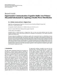
A. Effect on Average Throughput due to Frame Size First, we consider a heavy traffic load scenario where the users’ buffers are saturated most of the time. We use a sufficiently large packet arrival rate 𝜆 = 6.64 packets per slot with a maximum of 𝐿 = 7 packets arriving in a user’s buffer. The buffer size 𝑄 for all users is set to 100 packets. Fig. 1 shows that 𝑇 increases till the frame size 𝑁 reaches 4 slots for cases where 𝑈 = 2 channels and 𝑈 = 3 channels. Fig. 1 also shows that 𝑇 increases till the frame size 𝑁 reaches 6 slots for cases where 𝑈 = 4 channels and 𝑈 = 5 channels. It can be seen from Fig. 1 that the higher throughput can be achieved using the proposed scheduling compared to the slotbased scheduling (i.e., 𝑁 = 1).
40
Fig. 1 also shows that 𝑇 decreases for large frame sizes. This is due to the following reasons: 1) The transitions for channel status and channel mode can be more accurately estimated for a small frame size compared to a large frame size. Consequently, the calculated expected throughput 𝑇𝑓 (𝑢, 𝑣) is also more accurate for a small frame size compared to a large frame size. 2) For a large frame size, some of the channel resources may be wasted. For example, for a network with 𝑈 = 2 channels and frame size of 𝑁 = 10 slots, the channel capacity (depending on 𝑐𝑛 and 𝑏𝑛 ) has a range of [0, 268] packets per frame whereas the number of packets that can be transmitted by a user (depending on 𝑎𝑛 and 𝑞𝑛 ) has a range of [0, 163] packets. Consequently, when the users cannot fully utilize the channel capacity, the throughput drops. 3) When the frame size is large, even for the user with maximum estimated throughput may be experiencing bad channel condition in some slots within the frame, which causes lower throughput.
Percentage of packet drop, D (%)
35
8
10
12
14
16
Average throughput, T (packets/slot)
4
6
8
10
12
14
16
18
20
V. C ONCLUSION We have proposed a queue-aware frame-based opportunistic spectrum scheduling scheme for CRN. The proposed scheme differs from the existing frame-based schemes in its ability to handle fast channel conditions. By taking the queue status into consideration, we have presented a Markov chain formulation to estimate the maximum expected throughput over a frame for each channel based on the channel and queue information. We have shown that the proposed scheduling scheme outperforms the slot-based scheduling scheme in terms of throughput and packet drop. Also, the proposed scheduling scheme incurs smaller overhead than that of the slot-based scheduling scheme.
channels channels channels channels 18
2
Consider a network with 𝑈 = 5 channels and 𝑉 = 8 users. Both schemes require 𝐿𝑜𝑣 = 1744 bits for each scheduling instance. However, using a frame size of 𝑁 = 6 slots (which leads to the best performance for the case of 𝑈 = 5 channels and 𝑉 = 8 users, as shown in Fig.1) the scheduling overheads over a frame can be reduced by 80% using the proposed scheduling scheme.
3
6
0
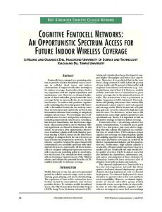
Fig. 2. Percentage of packet drop 𝐷 under different frame size 𝑁 for 𝑉 = 8 users, 𝑈 = 2 channels and varying 𝑄
4
4
Q=150 packets
Frame size, N (slots)
5
2
10
Q=200 packets
6
0
15
0
7
1
20
Q=100 packets
8
U=2 U=3 U=4 U=5
25
5
9
2
30
20
Frame size, N (slots)
Fig. 1. Average throughput 𝑇 under different frame size 𝑁 for various network settings
R EFERENCES
B. Effect on Packet Drop due to Frame Size Next, we consider a light traffic load scenario. We choose the network setting with 𝑉 = 8 users and 𝑈 = 2 channels.We use an average arrival rate of 𝜆 = 2 packets per slot with a maximum of 𝐿 = 3 packets arriving at a user’s buffer. The buffer size is varied between 𝑄 = 100 to 𝑄 = 200 packets. Fig. 2 shows that as the buffer size increases the percentage of packet drop (𝐷) decreases. It can be seen that the slot-based case has a higher 𝐷 compared to the frame-based case (up to 𝑁 = 10 slots). However, it can be observed that for large frame sizes the 𝐷 increases. This is because our scheduling scheme allocates 𝑈 users during each frame and when the frame size is large the waiting time for the unallocated users increases causing more packet drops. C. Savings in Scheduling Overhead The slot-based scheduling incurs 𝑁 times more scheduling overheads over a frame compared to the proposed scheduling scheme. Therefore, the scheduling overheads over a frame can be reduced by (1 − 1/𝑁 )% using the proposed scheme.
5
[1] Federal Communications Commission, ”Spectrum policy task force,” in Rep. OET Docket No. 02-135, Nov.2002. [2] T. V. Krishna and A. Das, ”A survey on MAC protocols in OSA networks,” Computer Networks, vol. 53, no. 9, pp. 1377–1394, 2009. [3] M. Thoppian, S. Venkatesan, R. Prakash and R. Chandrasekaran, ”MAClayer scheduling in cognitive radio based multi-hop wireless networks,” in Proceedings of International Symposium on World of Wireless, Mobile and Multimedia Networks (WoWMoM), June 2006. [4] J. Tang, S. Misra and G. Xue, ”Joint spectrum allocation and scheduling for fair spectrum sharing in cognitive radio wireless networks,” Computer Networks, vol. 52, no. 11, pp. 2148–2158, 2008. [5] K. Hamdi, W. Zhang amd K. B. Letaief, ”Uplink scheduling with QoS provisioning for cognitive radio systems,” in Proceedings of Wireless Communications and Newtroking Conference (WCNC), pp. 2592–2596, March 2007. [6] D. Gozupek and F. Alagoz, ”Throughput and delay optimal scheduling in cognitive radio networks under interference temprature constraints,” Journal of Communications and Networks, vol. 11, no. 2, pp. 147–155, 2009. [7] M. M. Rashid, M. J. Hossain, E. Hossain and V. K. Bhargava, ”Opportunistic spectrum access in cognitive radio networks: A queuing analytic model and admission controller design,” in IEEE Conference on Global Telecommunications (GLOBECOM), pp. 4647–4652, Nov. 2007. [8] Q. Liu, S. Zhou and G. B. Giannakis, ”Queuing analysis with adaptive modulation and coding over wireless links: cross-layer analysis and design,” IEEE Transaction on Wireless Communications, vol. 40, no. 3, pp. 1142-1153, May 2005.