International Journal of Computer Applications (0975 – 8887) Volume 180 – No.7, December 2017
An SPL Framework based Rapid Development of UAVs using FeatureIDE: A Case Study Md. Mottahir Alam
Asif Irshad Khan
Anoop Kumar Sharma
PhD Scholar Dept. of Computer Engineering, Singhania University, Rajasthan, India
Dept. of Computer Science, King AbdulAziz University, Jeddah, Saudi Arabia
Dept. of Computer Science, Singhania University Rajasthan, India
ABSTRACT Software product line engineering(SPLE), through the modeling of commonality and variability in a product family, offers a systematic solution to build a group of similar products at reduced development complexity and time to market due to their synergy and common goals. SPL models are often used to develop adaptive and configurable software systems such as a family of product lines. SPLE is usually implemented using different models. Implementing SPLE is very challenging. Different models are used to implement SPLE. Feature models are very prevalent nowadays because it helps to emulate the broad-view of product management, product design, and architecture and product configuration. This paper takes the case study of developing a family of UAV system using Improved Software Product Line (ISPL) via feature modeling. It shows how SPLs can be perceived as feature diagrams using feature modeling tool FeatureIDE to facilitate the development of product line family.
General Terms Software Product Line Engineering
Keywords Software Product lines, SPL, feature modeling, UAV family, case study.
1. INTRODUCTION SOFTWARE Product Line (SPL) is a well-known technique being used in industry since 90's to better the quality and reduce development time and costs of software products [1]. It is a well-planned, and decisive reuse of core software assets to produce a set of closely related software products that satisfy a particular market demand[2]. A family of products is usually characterized in terms of features, where each feature signifies an addition in the functionality of the product. These features are evolved from a reference architecture (RA) or generic architecture comprising a common set of assets that can be reused in different products of the product family [3].
In an SPL, a product is comprised of multiple components chosen from existing component libraries. These components communicate and collaborate through a common platform to achieve definite functionalities. Software companies use technologies and practices from different areas so as to increase the efficiency and quality of the set of built software products, also called as Software Product Line [4]. SPLs can be considered as software models by employing the idea of feature modeling engaging multiple software methodologies.
Software Product Lines (SPLs) Due to cost and time pressures, it is not practical for software firms to build a new product afresh against every new market demands. Therefore, there is a growing trend in the software industry to develop a set of similar but distinct software products instead of just a single product using the concept of software reuse. Software Product Line Engineering (SPLE) extends a solution to these industry challenges. SPLE is based on the idea of explicit representation of common and variable features among the product variants. Feature Models [5 ] [6 ] are often employed for this which models family of a product line. SPLE also involves the designing and control of a variable product line architecture and its constituent software components. In SPLE, common aspects of the product line are also called as core assets which comprise shared components, framework, tools, processes, documentation, test cases, etc. So, SPL, in essence, is a family/set of products outlined to take benefit of their common features and anticipated variability to enhance quality, delivery time and cut in cost. SPLE supports in designing, creating, delivering, maintaining and evolving a family of product line throughout the product development lifecycle. This paper is organized as follows: Section 2 deals with Software Product Lines (SPLs). Section 3 describes the Feature Model. Section 4 explains featurebased modeling tool FeatureIDE . Section 5 Feature Modeling using ISPL. Section 6 describes the case study of unmanned ariel vehicle (UAV). Lastly, section VII presents the conclusions.
2. FEATURE MODEL Feature modeling is a process of using features to identify commonality and variability in a group of similar products in a particular domain and then combining them to build a feature model. It was introduced by Kang et al. in 1990 [6]. It is used to control the variability in SPL approach, offering a hierarchical notation of the product features.
1
International Journal of Computer Applications (0975 – 8887) Volume 180 – No.7, December 2017
Feature models have two components. Its first element is the feature diagram that is a graphical or visual representation of a feature model combining features in a tree-like structure in the form of some relationships. The second part is additional constraints termed as cross-tree constraints as they do not depend on the tree-structure of the feature diagram. Cross-tree constraints represent any other relations existing among features. However, the semantics of feature models are fix and precise. This allows mapping of feature models to different logical representations.
4.
5.
A feature model is primarily used as an input to produce various assets like requirement specifications, design documents, and architecture outline. A feature can be defined as a property or attribute of a software system. It acts as the first-order entity [7] throughout the software lifecycle, and across the problem space and solution space, it can be understood simultaneously by domain experts, users, and developers. A feature model exemplifies all the potential member products of an SPL concerning features and the relationships among them. In a feature model, features are essential and distinguishing system requirements or components for an SPL [ ]. Features do not exist in separation, but there exist different relationships among them. Various kinds of associations between any parent feature and its child features can be summarized as: I. II. III. IV.
Mandatory: It means that the child feature is compulsory. Optional: It implies that the child feature is discretionary. OR: It indicates that at least one among the subfeatures necessarily be chosen. Alternative (XOR): It implies that only one from the sub-features is to be selected.
6.
7.
8.
9.
Besides, the parent-child relationships among features, crosstree constraints are supported, like:
A requires B – If a feature A is picked for a particular product, then the feature B must be chosen. A excludes B – Features A and feature B cannot exist simultaneously in the same product.
Various tools supporting feature modeling exists which address a wide variety of different concerns.
10. 11. 12.
These tools have their own feature modeling notations and constraint languages in order to analyze the common and variable features to form the basis of product line family. The different language constructs required in any feature modeling tool are as follows: 1.
2. 3.
Mandatory Features realize commonalities that are sure to be incorporated in a configuration if their parent feature is chosen. Optional Features express variabilities that may or may not be selected in a configuration. Feature Cardinality specifies a minimum and maximum number for how often a feature may be selected. It can be regarded as an option to the specific variation type for mandatory features and optional features. Sometimes, it is also used to represent multiple instances of the same feature as
13.
cloned features by enabling maximum cardinalities greater than 1. Attributes are marked variables of features that filter configuration choices so that, other than selection of features, precise values for attributes may be taken. We can define a specific type to the attributes, which outlines permissible values. Types of attributes can be classified into discrete (finite or infinite) and continuous domains. Feature Versions include variability in time in feature models [8][9]. It may be used to maintain two versions per feature representing the state of the feature model‘s structure and its associated implementation. However, it does not allow using them as configurable units. It can also be used to support specification of multiple feature versions with interdependencies to represent feature versions as a configurable unit. Layers of feature models provide a separation of concerns for different sources of variability. It is also used as layers for capability, operation settings, domain technologies, and implementation techniques[6]. It improves the reuse of feature models as well as assists scalability. External Features allow referencing of features that are defined in other feature models [10]. For instance, it can be employed in combination with layers of feature models when referencing features of different feature models [11]. Binding Times select at which time a feature should have to be configured. Standard binding times are at compile time or run time [12]. Sometimes, attributes in the features can also be used to specify the binding time [13]. Researchers also tagged a label on the connector linking features to mark the binding time. Resource Mapping enables linking of different resources with the features in a feature model [14]. It also presents a mapping of features for illustrations, displaying only particular parts of a feature model to collaborators of the feature model. Furthermore, it outlines preferences for the configuration and specific hardware to the features. Alternative-Groups select only one of the contained features, which makes them mutually exclusive. Or-Groups permit selection of at least one of the contained features. Group Cardinality stipulates the minimum and a maximum number of selectable features in any group. Hence, it may be regarded as an alternative to the specific variation type of groups as alternative-groups and or-groups [15]. Unlike the alternative-groups and or-groups, group cardinality supports additional restrictions on selections in a group. Multiple Groups express the possibility that a feature can have more than one child group, such as a feature having two alternative-groups. Numerous notations do not distinctly reveal whether they support multiple groups or not. Czarnecki and Eisenecker [17] appear to be the first who explicitly support multiple groups. There are various tools available which support feature modeling such as FeatureIDE, S. P. L. O. T. (Software Product Line Online Tools), Pure::Variants, Feature Model Plugin, PULSE-BEAT, FeatureMapper, MetaEdit+,
2
International Journal of Computer Applications (0975 – 8887) Volume 180 – No.7, December 2017 FaMa Tool FAMILIAR.
suite,
BeTTy
Framework,
and
The modeling methods mentioned above are all to extract the names of features and build their relationship, the features obtained from extraction are not the smallest unit in concept, which only show the problems to be solved, i.e. these feature modeling methods only extract the extension of products, not clearly explain how to solve problems, and fail to understand the variability and relationships between features in depth. So the ultimate feature models are at relatively higher level of abstraction, the relationship between features are more semantically vague [1].
Fig 1: Feature Diagram Example
Fig 2: Feature model of drone system.
3. FEATUREIDE: A TOOL FOR FEATURE-BASED SPL DEVELOPMENT The heading of a section should be in Times New FeatureIDE is an Eclipse-based IDE which supports the feature-based development of software systems. It was first introduced in FODA (Feature-Oriented Domain Analysis) method to extract and interpret commonalities and variability of software systems in a particular domain [6]. It supports all phases of feature-based development of SPLs, namely, domain analysis, requirements analysis, product-line design and architecting, product line implementation, product line testing, delivery, maintenance, and evolution. Feature models define features in a domain—and their relationships. Feature models are generally used to gather the information and data from domain experts concerning customer requirements, system potentials, system efficiency, and configurations [16]. The term Feature is used to express the understanding of the general capabilities of systems by end users, managers, and developers. Features can be classified as [7] [17] [18]: i)
problem space features: They are commonly used to express systems‘ specifications established during domain analysis and requirements engineering;
ii)
solution space features: They refer to the detailed realization of systems developed during domain engineering, usually by establishing mappings of the features to code,
iii)
configuration space features: They are used to facilitate the extraction of distinct products by managing variability.
This tool is under continuous evolution that adds to new features in it. Feature IDE provides a means to assist featurebased development through following:
A Feature Model Editor, which is both graphical and text-based. Constraint Editor. Configuration Editor for adding and editing of features. Provide source code abstraction for SPL. Support for refactoring, generalizations, etc. Statistics display of FeatureIDE project. Provide outline view of feature model. Supports Collaboration Diagram for Feature Diagram.
4. OVERVIEW OF THE IMPROVED SPL FRAMEWORK A security enabled framework for software product line development is proposed with a high abstract level of software product line (SPL) architecture as shown in Fig5. The model is a mix of aspect-oriented and the feature-oriented approach. The aspect-oriented approach addresses crosscutting concerns and functional behaviors of SPL while the feature-oriented approach is used to capture variability and commonality of product lines. The detailed explanation of the proposed model is as follows: The model has two high-level processes: domain engineering and application engineering. The main aim of domain engineering is to identify and develop reusable artifacts for reuse later in the application engineering phase. Application engineering targets building of software products using the identified reusable artifacts.
3
International Journal of Computer Applications (0975 – 8887) Volume 180 – No.7, December 2017
Fig 3: Shows a high abstract level of Software Product Line (SPL) Architecture
4.1 Domain Engineering Phase Domain Engineering requires common and variable requirements of the product line family as inputs and generates reusable core assets such as components, framework, a library, tools or a platform, etc. The core activities of the domain engineering phase are described as follows [19]:
Business Feasibility Study Product Line Scoping Product Line Requirement Analysis Security Policy and Security Modeling Product line design and architecting Product line Implementation Product line Testing
4.2 Application Engineering Phase Application engineering deals with requirements specifications of individual products of the software product line family are considered, and a customer-specific product is developed by using the generic architecture and reusing the core assets from domain engineering as much as possible.
Fig 4. Architecture diagram of the UAVs system.
4
International Journal of Computer Applications (0975 – 8887) Volume 180 – No.7, December 2017 Following are the major activities carried out to create tailored products during application engineering: Application Requirement Application Design and Architecting Application Implementation Application Testing Delivery, Evolution, and Maintenance For a detailed description, refer to [16].
5. CASE STUDY Unmanned Aerial Vehicle (UAV) or drone is an aircraft that fly without pilot on-board. They are also called "flying robot" or ―eyes in the sky.‖ It is remotely managed through softwarecontrolled flight programs in its embedded systems operating in coordination with aboard GPS and various sensors. Apart from its uses in the military like in intelligence gathering[20], anti-aircraft target, and weapons platforms[21-24], UAVs are also finding large-scale applications in agriculture, traffic
monitoring, rescue mission[25], real estate evaluations, weather monitoring[26-28], surveying, business drone-based photography and videography, wildlife monitoring, and conservation, and even delivery services. While techniques and capabilities may vary, all UAVs posses these common features: i) ii)
They are energized by rechargeable batteries. They are managed either autonomously or with a remote. iii) They have 4-8 rotors. iv) They employ GPS to track location. v) They are based on a fail-safe mechanism like returnto-home technology. vi) They contain a camera with both videos as well as still image capabilities.
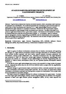
Fig 5: Feature-diagram example of a UAV system
5
International Journal of Computer Applications (0975 – 8887) Volume 180 – No.7, December 2017 While designing a family of UAVs under the SPLD approach, although the core architecture for UAV product line remains almost the same, key features are such as propeller selection, motor variety, airfoil selection, wing-size, and span of tilting wing segment are systematically selected depending on the probable application of specific UAVs.
Fig 6. UAV Outline View In this case study, FeatureIDE is employed to simulate and create UAV feature models. A typical feature diagram for the UAV product line is represented in Fig. 5. The FeatureIDE tool provides support for defining mandatory features, optional features, and constraints of the UAV product line. These features are displayed in a Feature model diagram of the product line as shown in Fig 5. As we know, the nodes in Fig 5 represents features while edges represent dependency among the features. The constraints are also a part of feature model diagram. In the feature-oriented programming based on the feature modeling, each feature is implemented as an independent feature model. The UAV product line uses a total of 38 features such as motor-configuration, sensor, connectivity, battery, software-support, media, etc. as shown in Fig 11. Out of 38, there are 37 concrete features, 1 abstract feature, 29 primitive feature, 9 compound features, and 5 constraints. The outline as in Fig. 6 provides the overall outline of the UAV product line feature model, summarizing the mandatory features, optional features, and the product line constraints where the solid circles show the mandatory features, hollow circles displays the optional features, and another symbol represents the or-relations among the features.
Fig 7: Collaboration Diagram for the UAV system The root of this feature diagram is "UAV" which represents a UAV product. It has six mandatory children with Motor configuration, Sensor, Connectivity, Battery, Software Support, and Battery. It also has one optional child as Other Features. The feature diagram is equivalent to following conjunction: root(UAV) ∧ mandatory(UAV, Motor configuration) ∧ mandatory(UAV, Sensor) ∧ mandatory(UAV, Connectivity) ∧ mandatory(UAV, Battery) ∧ mandatory(UAV, Software Support) ∧ mandatory(UAV, Media) ∧ optional(UAV, Other Features) ∧ alternative(Motor Configuration,{Tricopter,Quadcopter, Hexacopter, Y6, X8}) ∧ alternative(Sensor,{Accelerometer, Magnetometer})
GPS,
Barometer,
∧ alternative(Connectivity,{Wireless, GPS) ∧ alternative(Battery,{NiCd, Ni-MH, LiPo}) ∧ alternative(Software Support,{takeoff, land, arm, disarm, checkbatterystatus,getPosition,flylocation,send Pictures,emergencyLanding})
6
International Journal of Computer Applications (0975 – 8887) Volume 180 – No.7, December 2017 ∧ alternative(Media,{Camera, Onscreen}) ∧ or(Other Features,{Wireless Telemetry Kit, Optical Sensor, Battery Monitor}) ∧ alternative(Camera,{Digital, Analog}) ∧ (···)
Fig 9: Configuring features for the UAV system for specific features combinations
5.2 Implementation of Software Variability
Fig 8: show collaboration map for the UAV system. The Collaboration Diagram displays the feature model for UAV in terms of the main classes being involved and the features they represent. Additionally, it also describes the other classes which define the main classes.
5.1 Modeling Variability with Feature Models In a FeatureIDE, the feature model of the UAV product line is stored in the UAVmodel.xml file of UAV project. The feature model editor for the UAV project as shown in Fig. 5 has three tabs which allow the product-line developers to the edit feature model. The FeatureIDE editor supports: i)
editing of feature diagrams for the UAV product line.
ii) managing the order of features to ensure correct product generation of UAV product line. iii) direct editing of the textual representation in the UAVmodel.xml file. Hence, with the editor, the development team can add, remove, and even change features and their dependencies. It is also possible to add cross-tree constraints to the feature model. Even an arbitrary propositional formula can be defined in the editor with the set of existing features. FeatureIDE offers an additional dialog that ensures the syntactical correctness of described cross-tree constraints. The dialog can be opened using the context menu or a double-click on an existing cross-tree constraint. Using the Constraint Dialog, the developer immediately gets feedback about the correctness of the constraint to prevent the creation of incorrect constraints.
A FeatureIDE project like UAV project comprises of two source folders: the ―src‖ folder for generated source files and the ―features‖ folder for implemented artifacts. Thus, the editable implementation artifacts of the UAV product line are located in the ―features― folder. In contrast, the ―src― folder is only the output folder for the generator and the content changes by each product generation (i.e., build process). Therefore, it is not intended to manually change the files of ―src‖ folder. Nevertheless, the ―src‖ folder can be helpful if program failures occur and more details are needed to find the error. The folder consists of a set of subfolders that represents the feature modules of the UAV project. Each subfolder represents a unique concrete feature of the UAV feature model as described in the UAVmodel.xml. For instance, the UAV project as can be seen in Fig. 3.4 consists of 37 concrete features that are represented as subfolders in the source folder features. Further, each of the feature modules contains implementation artifacts, and Java files, which we can be edited to change the behavior of products of the UAV product line. It is to be noted that the implementation of a product line and the respective implementation procedure differs according to the used programming language (e.g., Java, C++) and generation mechanism (e.g., preprocessors).
7
International Journal of Computer Applications (0975 – 8887) Volume 180 – No.7, December 2017
Fig 10: Configuring features for the UAV system for specific features combinations
Fig 11 . FeatureIDE for UAV product line
5.4 Product Generation and Execution: 5.3 Creating Configurations: Before running a specific product of the UAV product line, we need to select all features that are to be included in a given product. FeatureIDE provides configuration files for this purpose where the specific selections are stored. As described above, all existing configurations of a project are stored in the directory ―config,‖ and the active configuration (i.e., the product that is used for the build process) is displayed as green. Typically only the active configuration is built automatically on each change. As a developer, we can use FeatureIDE‘s Configuration Editor to have a look at the selected features of a *.config file and to change the selection.
Once the feature modeling, feature implementation, and product selection for the UAV product line is done, we can start to build and run a specific UAV product. FeatureIDE has in it all well-known procedures that Eclipse provides for a project build and launch. Thus, like Eclipse, FeatureIDE offers multiple ways to create a Run Configuration for projects.
Therefore, the FeatureIDE‘s Configuration Editor comprises of a configuration page, an advanced configuration page, and a source tab for the textual representation of the file. The Source tab textually presents all selected features, whereas the Configuration and Advanced Configuration tabs support the configuration process and ensure that the selection does not lead to invalid configurations.
Fig 12. Configuration file for UAV system
8
International Journal of Computer Applications (0975 – 8887) Volume 180 – No.7, December 2017 Depending on the programming language, the submenu varies slightly. The FeatureIDE UAV project is based on a Java project, and so, the submenu allows us to create and launch a Run Configuration for Java. After that, we can reuse the created Run Configuration to relaunch the UAV project‘s configuration. Sometimes the created Run Configuration cannot launch the project successfully due to false settings, such as possible start parameters. In this case, we have to set up the created Run Configuration. So, the developer can use the menu entry Run Configurations. Using this menu entry, we can open the default dialog for Eclipse configurations that allow us to edit or create all kinds of configuration settings. Depending on the type of the Run Configuration, we can define all needed start information, such as the starting class or start parameters.
[7] Lettner, D., Eder, K., Grünbacher, P. and Prähofer, H., 2015, September. Feature modeling of two large-scale industrial software systems: Experiences and lessons learned. In Model Driven Engineering Languages and Systems (MODELS), 2015 ACM/IEEE 18th International Conference on (pp. 386-395). IEEE.
6. CONCLUSION
[10] van Gurp, J.; Bosch, J.; Svahnberg, M.: On the Notion of Variability in Software Product Lines. In: Proceedings of the Conference on Software Architecture. 2001.
This research work proposed an SPL based feature model for an unmanned aerial vehicle (UAV). FeatureIDE, which is an Eclipse-based feature modeling tool, is used to represent a family of products for UAV system. The paper emphasized in details various aspects of UAV product line. The feature model successfully generated various aspects of UAV product line such as feature diagram, collaboration diagram view, its configuration, Feature IDE Statistics, etc to facilitate the development of product line family. It was observed that distinct sets of UAV could be outlined depending on the various mandatory, optional and exclusive features selected for the UAV product line.
[8] [SSA14a] Seidl, Christoph; Schaefer, Ina; Aßmann, Uwe: Capturing Variability in Space and Time with Hyper Feature Models. In: Proceedings of the 8th International Workshop on Variability Modelling of Software-intensive Systems (VaMoS). VaMoS‘14, 2014. [9] [ME08] Mitschke, R.; Eichberg, M.: Supporting the Evolution of Software Product Lines. In: ECMDA Traceability Workshop. ECMA-TW, 2008.
[11] Bak, Kacper; Czarnecki, Krzysztof; Wasowski, Andrzej: Feature and Meta-models in Clafer: Mixed, Specialized, and Coupled. In: Proceedings of the Third International Conference on Software Language Engineering. SLE‘10, Springer-Verlag, Berlin, Heidelberg, pp. 102–122, 2011. [12] Griss, M. L.; Favaro, J.; Alessandro, M. d‘: Integrating Feature Modeling with the RSEB. In: Proceedings of the 5th International Conference on Software Reuse. ICSR ‘98, IEEE Computer Society, Washington, DC, USA, 1998.
It was concluded that the FeatureIDE tool successfully supported all the phases of feature-oriented product line development of UAV product line which was mandatory for this case study. Further, FeatureIDE tool endorses both domain engineering and application engineering by assisting in implementing variability in product lines, providing support to configure products, and finally, assisting in generation and execution of products for a product line.
[13] van Gurp, J.; Bosch, J.; Svahnberg, M.: On the Notion of Variability in Software Product Lines. In: Proceedings of the Conference on Software Architecture. 2001.
7. REFERENCES
[15] Riebisch, M.; Bollert, K.; Streitferdt, D.; Philippo ¨ w, I.: Extending Feature Diagrams with UML Multiplicities. In: 6th World Conference on Integrated Design & Process Technology (IDPT2002). June 2002.
[1] Khan, A.I., Alam, M.M. and Al Jedaibi, W., Variability Management in Software Development using FeatureIDE: A Case Study, International Journal of Scientific & Engineering Research, Volume 6, Issue 1, January-2015, ISSN 2229-5518
[14] Schroeter, Julia; Lochau, Malte; Winkelmann, Tim: Multi-Perspectives on Feature Models. In: Model Driven Engineering Languages and Systems. Springer Berlin Heidelberg, 2012.
[2] J. Bosch, Design and Use of Software Architectures: Adopting and Evolving a Product Line Approach, Addison-Wesley, 2000
[16] Alam, M.M, Khan, A.I, Zafar, A. Md. Mottahir Alam, Asif Irshad Khan, and Aasim Zafar. A Secure Framework for Software Product Line Development. International Journal of Computer Applications 159(4):33-40, February 2017.
M. Steger et al., ‗Introducing PLA RK Bosch Gasoline of System: Experiences and Practices‘ in: Proc. of the Software Product Line Conf. 2004, S. 34-50
[17] Czarnecki, K., Eisenecker, U.W.: Generative Programming: Methods, Tools, and Applications. Addison-Wesley, Boston (2000)
[4] Alam, M.M, Khan, A.I, Zafar, A., ―A Comprehensive Study of Software Product Line Frameworks‖, International Journal of Computer Applications (0975 – 8887) Volume 151 – No.3, October 2016.
[18] Kang, K.C., Kim, S., Lee, J., Kim, K., Shin, E., Huh, M.: FORM: a feature-oriented reuse method with domainspecific reference architectures. Ann. Softw. Eng. 5, 143–168 (1998)
[5] K. Czarnecki, U.W. Eisenecker, Generative Programming:Methods, Tools, and Applications, Addison-Wesley, 2000
[19] Alam, M.M., Khan, A.I. and Zafar, A., An Empirical Study of the Improved SPLD Framework using Expert Opinion Technique., (IJEACS) International Journal of Engineering and Applied Computer Science, Volume: 02, Issue: 03, March 2017 ISBN: 978-0-9957075-4-2
[3]
[6] K. Kang, et al., Feature Oriented Domain Analysis (FODA) Feasibility Study, Technical report CMU/SEI90-TR-021, Software Engineering Institute, Carnegie Mellon University, 1990
[20] Lazarus, S., Shanmugavel, M., Tsourdos, A., Zbikowski, R., and White, B. A., ―Airborne mapping of complex obstacles using 2D splinegon,‖ American Control
9
International Journal of Computer Applications (0975 – 8887) Volume 180 – No.7, December 2017 Conference, Seattle, WA, June 11-13 2008, pp. 1238– 1243. [21] Klesh, A., Girard, A., and Kabamba, P. T., ―Path planning for cooperative time-optimal information collection,‖ American Control Conference, Seattle, WA, June 11-13 2008, pp. 1991–1996. [22] Lechevin, N., Rabbath, C. A., Shanmugavel, M., and amd Brian A. White, A. T., ―An integrated decision, control and fault detection scheme for cooperating unmanned aerial vehicle formations,‖ American Control Conference, Seattle, WA, June 11-13 2008, pp. 1997– 2002. [23] Karaman, S. and Frazzoli, E., ―Complex mission optimization for multiple-UAVs using linear temporal logic,‖ American Control Conference, Seattle, WA, June 11-13 2008, pp. 2003–2009. [24] Serchele, R., Cataldo, L., Smith, B., and Ostis, F., ―Smart wide area munitions for UAVs,‖ AUVSI North America 2006 , Orlando, FL, 2006. [25] Pratt, K., Murphy, R., and Stover, S., ―Requirements for semi-autonomous flight in miniature UAVs for structure inspection,‖ AUVSI North America 2006, Orlando, FL, 2006. [26] Davis, R. and Holmgren, P., ―Remote sensing and forest monitoring in FRA2000 and beyond,‖ Forest resources assessment working paper - 008, Forestry Department, Food and Agriculture Organisation of the United Nations, Rome, 1999. [27] Tomppo, E., Czaplewski, R., and Makisara, K., ―The role of remote sensing in global forest assessment,‖ Background paper for Kotka IV Expert Consultation, Kotka, Finland, July 2002.
AUTHOR'S PROFILE Mr. Md Mottahir Alam is a Ph.D. scholar in the Computer Science & Engineering in Singhania University, India. He has six years of experience as Software Engineer (quality) for leading software multinationals, where he worked on projects for companies like Pearson and Reader's Digest. He is ISTQB Certified Software Tester. He has received his Bachelor's degree in Electronics & Communication and Masters in Nanotechnology from Jamia Millia Islamia University, New Delhi, India. Mr. Alam research interest includes Software Engineering esp. Software Product Line Engineering, Software Reusability, Component-based and Agent-based Software Engineering. He can be reached at
[email protected]. Dr. Asif Irshad Khan is working as a faculty member in the Department of Computer Science, FCIT, King Abdulaziz University, Jeddah, Saudi Arabia. He has over fifteen years of experience as a professional academician and researcher. Dr. Khan received Ph.D. in Computer Science and Engineering from India, and Master & Bachelor degrees in Computer Science from the Aligarh Muslim University (A.M.U), Aligarh, India. He has published several research articles in leading journals and conferences. He is a member of the editorial boards of international journals, and his current research interest includes Software Engineering with a focus on Component Based and Software Product Line Engineering. He can be reached at
[email protected]. Dr. Anoop Kumar Sharma is working as an assistant Professor in the Computer Science Department, Singhania University, Rajasthan. His current research interest includes elearning, mobile learning, virtual learning environments and mobile ad hoc networks. He has a number of research papers to his credits.
[28] Maslankik, J., ―Polar remote sensing using an unpiloted aerial vehicle (UAV),‖ Seminar, ATOC7500, November 2002.
IJCATM : www.ijcaonline.org
10