Dec 29, 2008 - System (AS), the Ant Colony System (ACS), and the MAX-MIN Ant. System (MMAS). In order to make these simple algorithms effective in such a ...
Brock University Department of Computer Science
Ant Colony Optimization Algorithms with Local Search for the Dynamic Vehicle Routing Problem Andrew Runka December 29, 2008 Advisor: Dr. Beatrice M. Ombuki-Berman 1
Abstract This report demonstrates the use of effective local search to improve the performance of simple Ant Colony Optimization (ACO) algorithms as applied to an extension of the Vehicle Routing Problem (VRP) known as the Dynamic Vehicle Routing Problem (DVRP). The static VRP presents all orders a priori, however the DVRP requires scheduling to begin without a complete knowledge of all customer’s locations, demands, and/or times. In recent years, much focus has been given to the study of meta-heuristics for use in solving static VRPs. Currently, however, emphasis is being put on DVRPs as they present a better model with real-life applicability and challenges. The approach taken in this paper is to model the DVRP as a series of static VRPs, and solve each one by applying the ACO meta-heuristic. Three simple instantiations of the ACO meta-heuristic are used, namely, the Ant System (AS), the Ant Colony System (ACS), and the MAX-MIN Ant System (MMAS). In order to make these simple algorithms effective in such a difficult problem space, they are augmented with an insertion based local search, as well as a greedy step-based route scheduler. The algorithms are shown to outperform the only published ant-based algorithm for the DVRP model presented here, as well as achieve 4 new best known results using publicly available benchmark problem instances.
2
Acknowledgment I would like to thank everyone who contributed to this project in every small form. To all those who answered my many questions, to all those who guided me to the answers, to all those who put up with me for the last year, and to all those who didn’t get to, Thank You! More specifically I would like to thank Frank Hanshar for his willingness to explain the smallest details, my friends and family for their continued support, and of course my supervisor Dr. Ombuki-Berman without whom none of this would have been possible.
3
Contents 1 Introduction
6
2 Background 2.1 Problem definition . . . . . . . . . . . . . 2.1.1 Static Vehicle Routing Problem . . 2.1.2 Dynamic Vehicle Routing Problem 2.2 Ant Colony Optimization . . . . . . . . . . 2.2.1 Ant Colony System . . . . . . . . . 2.2.2 MAX-MIN Ant System . . . . . . .
. . . . . .
. . . . . .
. . . . . .
. . . . . .
. . . . . .
. . . . . .
. . . . . .
. . . . . .
. . . . . .
. . . . . .
. . . . . .
8 8 8 9 11 13 14
3 The ACO-DVRP algorithm 14 3.1 Event Handler . . . . . . . . . . . . . . . . . . . . . . . . . . . 14 3.2 ACO Module . . . . . . . . . . . . . . . . . . . . . . . . . . . 16 4 Experimental Setup and Discussion 4.1 Benchmark data . . . . . . . . . . . . . . . . . . . . . . . . . 4.2 Experimental Setup . . . . . . . . . . . . . . . . . . . . . . . 4.3 Results and Discussion . . . . . . . . . . . . . . . . . . . . . 4.3.1 Local Search and Route Scheduler . . . . . . . . . . . 4.3.2 Cloning vs. no cloning . . . . . . . . . . . . . . . . . 4.3.3 Comparison of ant-based algorithms with local search vs published ant based algorithm . . . . . . . . . . . 4.3.4 Comparison of ant-based algorithms with local search vs published GA and Tabu search . . . . . . . . . . . 5 Conclusion
. . . . .
17 17 18 21 21 22
. 25 . 27 28
6 Appendix A 32 6.1 Tables of Results . . . . . . . . . . . . . . . . . . . . . . . . . 32
4
List of Figures 1 2 3 4 5 6 7
Sample DVRP routing scheme . . . . . . ACO Meta-Heuristic Pseudo-code . . . . ACO-DVRP structure diagram . . . . . Event Handler Pseudo-code . . . . . . . Distribution of customers . . . . . . . . . Local Search vs Step Scheduler pressures Cloning vs No cloning . . . . . . . . . .
. . . . . . .
. . . . . . .
. . . . . . .
. . . . . . .
. . . . . . .
. . . . . . .
. . . . . . .
. . . . . . .
. . . . . . .
. . . . . . .
. . . . . . .
. . . . . . .
11 12 15 16 19 22 24
ACO parameter settings . . . . . . . . . . . . . DVRP parameter settings . . . . . . . . . . . . AS with cloning vs. AS without cloning . . . . . ACS with cloning vs ACS without cloning . . . MMAS with cloning vs MMAS without cloning AS vs ACS vs MMAS . . . . . . . . . . . . . . AS clone vs Montemanni’s ACS . . . . . . . . . AS no clone vs Montemanni’s ACS . . . . . . . ACS clone vs Montemanni’s ACS . . . . . . . . ACS no clone vs Montemanni’s ACS . . . . . . MMAS clone vs Montemanni’s ACS . . . . . . . MMAS no clone vs Montemanni’s ACS . . . . . AS and ACS vs. [1]’s GA and Tabu . . . . . . .
. . . . . . . . . . . . .
. . . . . . . . . . . . .
. . . . . . . . . . . . .
. . . . . . . . . . . . .
. . . . . . . . . . . . .
. . . . . . . . . . . . .
. . . . . . . . . . . . .
. . . . . . . . . . . . .
20 20 32 33 34 35 36 37 38 39 40 41 42
List of Tables 1 2 3 4 5 6 7 8 9 10 11 12 13
5
1
Introduction
The Vehicle Routing Problem (VRP) is widely studied in the literature. It has been the subject of experimentation using a number of methods including several meta-heuristics such as Genetic Algorithms and Ant Colony Optimization (ACO). The VRP serves as an effective test-bed for many heuristics due to its complexity and wide variety of extensions. Also, this problem is NP-hard [2], and abstracts many real-world applications, especially in the fields of logistics and transportation. The basic idea behind the VRP is that a fleet of vehicles, each with a limited capacity, are dispatched to service a set of customers. The objective being to travel the shortest total distance with all vehicles in the process. The Dynamic Vehicle Routing Problem (DVRP) is an extension of the traditional static VRP that has even more applicability to real world problems. The primary difference when extending the VRP to the DVRP is that the customers are not known in advance, but are revealed as the day progresses. Thus, the routes of the vehicles must adjust dynamically to accommodate new customers. This more accurately reflects many real-world pickup or delivery problems where not all customers are known prior to beginning the day. Larsen [3] describes a number of real-life applications of dynamic vehicle routing problems. Situations such as courier services, taxi services, and even emergency services operate on a dynamic basis where the vehicles are dispatched without a complete schedule of stops. For this reason, focus is being shifted from the static VRP, where much research in the use of metaheuristics has already been done, and is being placed on the DVRP. Due to the dynamism, DVRPs are more difficult to solve than static VRPs, and thus the use of approximation techniques has gained popularity for such problems. To use an exact approach to find a solution to such problems is highly infeasible as the length of time required to find an exact solution is likely much greater than the rate at which the problem state is evolving. A number of meta-heuristics have been applied to variants of DVRPs including tabu search [4, 5], and ACO [1, 6, 7]. Guntsch et al. [6] applied the ACO meta-heuristic to dynamic versions of the Traveling Salesman Problem (TSP) and the Quadratic Assignment Problem. They used a modified ACO algorithm called FIFO-Queue ACO that was geared towards faster convergence in a dynamic environment. Eyckelhof et al. [7] augmented the simple Ant System (described in Section 2.2) with a novel pheromone control procedure known as ’shaking’. This was then ap6
plied to a dynamic TSP. Both of these papers report that traditional ACO algorithms are capable of adapting to a dynamic environment, providing that the frequency of change or level of dynamism is low. The dynamic problems in both papers are solved as single congruent and evolving problem. Gambardella et al. [8] introduced a VRP-specific ACO variant known as Multiple Ant Colony System (MACS). MACS uses two ant colonies to first minimize the number of vehicles and second to minimize the total travel time. This approach proved to be effective in solving the Vehicle Routing Problem with Time Windows (VRPTW), and is one of the top performing ACO algorithms for the VRP to date. A survey of ACO algorithms applied to VRPs is found in [9]. A number of DVRP variants exist, including those studied by Larsen [3], Gendreau et al. [10], Lund et al. [11], and Ichoua et al. [12]. The DVRP variant employed in this report was originally proposed by Kilby et al. [13]. Montemanni et al.[1] then applied ACO to this DVRP providing the first benchmark results based on meta-heuristics for this data. The specific ACO implementation used in [1] is described as being “similar to the MACS-VRPTW algorithm”. In addition to creating benchmark results, [1] also introduces the “pheromone conservation procedure” for using ACO algorithms with the DVRP (described in 3.1). Following this, Hanshar et al. [14] applied a GA and simple Tabu search to this DVRP variant presenting the majority of the currently best-known solutions for the DVRP model introduced in [13] and extended by [1]. This report aims at expanding the use of meta-heuristics, specifically ACO to the DVRP model discussed in [13], [1], and [14]. The main contribution of this report is two-fold. First, to study the effect of local search on standard well-known ant-based algorithms. Secondly to further evaluate the use of ant-based algorithms as applied to DVRPs. The remainder of this report is structured as follows, Section 2 provides the background on the DVRP model and ant-based algorithms studied here. Section 3 presents the details of the implemented ant-algorithms with local search. Section 4 provides the experimental setup and discusses the results. Finally, Section 5 presents the conclusions and future work.
7
2 2.1
Background Problem definition
The DVRP variant considered in this report is based on the model first proposed in [13], and later adopted by [1] and [14]. In this model, the DVRP is transformed into a series of static VRP instances. The static VRP can be described as follows: A set of customers must be serviced by a fleet of vehicles. Each customer has a specific amount of demand, and each vehicle can only service a limited capacity of total demands. All customers must be serviced exactly once, and all vehicles must start and end their tours at a single depot. The objective is to find a routing scheme that describes which vehicles service which customers and in what order while minimizing the total travel distance over all vehicles’ tours. The total travel distance is often referred to as the total travel time, in this case there is an assumed constant speed of one and thus they are equivalent. 2.1.1
Static Vehicle Routing Problem
The VRP can be represented mathematically as an undirected weighted graph G = (V,A), where V = {v0 ,v1 ,...,vn } is a set of nodes representing the depot (v0 ) and the set of customers (v1 ,...,vn ), and A = {vi ,vj |vi ,vj ∈ V} is a set of weighted arcs fully connecting V, which represent the travel time/distance between customers. In addition, a homogenous set of m vehicles are used to service all customers exactly once. Each customer i is associated with a demand qi , and each vehicle is associated with a capacity P Q. A tour remains feasible if qi ≤ Q remains true for all customers i serviced by a given vehicle. The cost of any given solution can be calculated as Cost(Solution) =
m X k X
disti,i+1
(1)
j=0 i=0
where k is the size of route j, and disti,j is the distance between vi and vj or the weight along arci,j . Thus the objective is to find a solution which minimizes the cost function while maintaining feasibility.
8
2.1.2
Dynamic Vehicle Routing Problem
Dynamic vehicle routing is a generic term that refers to vehicle routing and scheduling in a dynamic environment as opposed to a static one. Many specific variants incorporate dynamism in terms of variable customer demands, variable arc weights between customers (simulating traffic levels), customer locations, etc. The main difference between the DVRP model studied here and the static VRP is that in the VRP all orders are known before any routing takes place, whereas in the DVRP routing begins on a small set of known orders, and as the day progresses new orders arrive which must also be accommodated into the routing scheme. This is accomplished by means of dividing the problem into a series of discrete time slices, each of which behaves similar to a static VRP instance. Kilby et al. [13], originally proposed that the algorithm run in real-time, that is, the length of the simulated working day would be equivalent to the actual working day. In such a case, a given time slice would stop when a new order arrived, and a new time slice would begin that would include the new order. Montemanni et al. [1] however, decided to maintain reasonable execution times for their simulations by limiting the total execution time to 1500 seconds or 25 minutes per working day. The working day was then divided into 25 equal time slices of one minute each. Hanshar et al. [14] later shortened this down to 30 seconds per time slice, due to implementation on a faster machine. In this case, all orders received during the execution of one time slice are collected until the beginning of the next time slice. They are then added to the list of serviceable customers. In this report, simulated timing is used as in [14]. A discrepancy arises between the simulated length of the working day Tsim and the actual duration of execution, which shall be denoted Treal . Every instance of the DVRP is associated with its own Tsim value. This is the simulated length of the working day. It is mapped to a real-time value by limiting the execution time of each time slice to Treal / nts , where nts is the number of times slices. Similarly, each time slice is associated with simulated and real-time values. For expressiveness we adopt the convention that all time values are simulated unless otherwise stated. Thus T and Tts will refer to the simulated length of the working day and simulated length of the time slice respectively, while Treal and Ttsreal will refer to their real-time equivalents. In each time slice, a given customer may be in one of three states: 1. not serviceable, not included in the routing scheme, 9
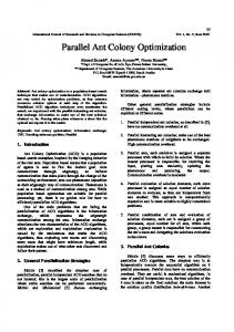
2. serviceable, position in routing scheme is not fixed, or 3. committed, position in the routing scheme is fixed. All customers are associated with an availability. That is, the time in which they become serviceable. Initially, a subset of the customers, those known a priori, are considered serviceable. These customers are considered to have carried over from the previous working day. The cutoff time or Tco is the point in the working day after which any new customers are postponed until the following day. That is, customers with an availability greater than T · 0.5 are postponed for processing. It has been adopted that these cutoff customers are used as the a priori customers for the given day. The remaining customers, those not known a priori, are initially considered not serviceable. Each time slice works by generating a tentative routing scheme. That is, it generates a routing scheme on the assumption that the system as a whole will remain unchanged until the end of the working day. This tentative routing scheme is improved during each time slice by permuting the order of serviceable customers. Each customer is associated with a given commitment time. This is the planned time during execution that the customer will be serviced. If the commitment time of a customer in the tentative routing scheme occurs within the next time slice, then that customer becomes committed and is no longer mutable starting from that time slice. A parameter, Tac , known as the advanced commitment time or commitment horizon, is introduced as a buffer for the commitment of customers. Vehicles must have Tac advanced notice before committing customers. In practice, this means that all customers within the next Tts + Tac are committed. Committed customers hold static positions in the tentative routing schemes of each subsequent time slice. Any improvements on the routing scheme are considered to start from the last committed customer on each route. An example of a DVRP scheduling and routing in progress is illustrated by Figure 1 as depicted in [14]. This shows a snapshot of the tentative routing scheme, with a number of committed customers (those connected to ”completed route segments”), and a number of serviceable customers (those connected by ”planned route segments”). Note that the arrival of a new request causes an alteration to the planned segments of a route.
10
Known request Immediate or new request Depot
New route segment Planned route segment Completed route segment
Figure 1: Sample DVRP routing scheme
2.2
Ant Colony Optimization
Ant Colony Optimization (ACO) is a meta-heuristic first proposed by M. Dorigo [15] that is modeled on the natural optimization behaviour of real ants known as foraging. In reality, a population of ants cooperate by use of pheromone trails to find optimal paths between a nest and a food source. The concept of pheromone was borrowed for ACO to act as a means of balancing between exploration and exploitation in a combinatorial optimization search space. There are a number of variants which embody the ACO metaheuristic, but all share the same essential structure. Figure 2 describes the pseudo-code for the ACO meta-heuristic. It is broken down into three main phases: generate solutions, update pheromone, and daemon actions. These are described in more detail below. The first phase encompasses the construction of solutions to the given problem. ACO algorithms can generate solutions for any problem that can be modeled as a graph. At each step during construction, each ant adds one vertex to its path. The ant will move from vertex i to vertex j with a probability calculated as follows: pi,j =
β α (τi,j )(ηi,j ) β α Σ(τi,j )(ηi,j )
(2)
where τi,j is the amount of pheromone on arci,j , α is a parameter that controls the amount of influence of τi,j on the decision, ηi,j is the desirability of arci,j , 11
procedure ACO MetaHeuristic while(not termination) GenerateSolutions() UpdatePheromone() DaemonActions() end while end procedure
Figure 2: ACO Meta-Heuristic Pseudo-code which is some problem specific knowledge (e.g. dist1 i,j for the VRP), finally β is the control parameter for ηi,j . This formula allows for the stochastic construction of a tour. At each state, an ant can choose between exploitation of a priori desirability information and a posteriori pheromone information, while maintaining the potential to explore less desirable solutions. Once a population of solutions has been generated, the second phase, known as pheromone update, takes place. This phase is typically where the ACO variants differ. The discussion here pertains to the simplest ACO algorithm known as Ant System (AS). The pheromone update can be separated into two steps: evaporation and deposit. The first step, evaporation, is calculated as follows: τi,j = (1 − ρ)τi,j (3) where τi,j is the amount of pheromone on arci,j and ρ is a parameter that controls the amount of evaporation. This formula is applied globally to every arc. The second step, deposit, is calculated for each ant, and typically takes the form: ( 1 , if ant travels arci,j k (4) ∆τi,j = Ck 0, otherwise where Ck is the cost of the kth ant’s solution. As this is done for each ant the effect accumulates on the arcs, and thus the following holds true: ∆τi,j =
m X k=0
12
k ∆τi,j
(5)
where m is the number of ants. The two aforementioned steps can thus be combined into the following pheromone update formula: τi,j = (1 − ρ)τi,j + ∆τi,j
(6)
By iteratively applying Formula 6, the arcs which are part of good tours through the graph will become condensed with more pheromone while the pheromone on the arcs that are not part of good tours will become scarce. The pheromone deposit increases the likelihood of exploitation of known good areas of search, while the pheromone evaporation maintains the potential for exploration of unknown areas of search. Thus the convergence of the algorithm is gradual allowing for an effective search of the solution space. The third phase of the ACO metaheuristic is daemon actions. This is a broad term referring to any post processing of the given solutions, such as a local search operation. The daemon actions used in this report are described in detail in Section 3. Next, two extensions of the AS algorithm are discussed in the following sections. 2.2.1
Ant Colony System
The Ant Colony System (ACS) was designed by Dorigo and Gambardella [16], as an improvement to the simple AS algorithm. It is still based upon the ACO metaheuristic, yet boasts some key changes from the AS that enable a more effective optimization strategy. The first change is the ‘pseudo-random proportional rule’ which states that with probability q0 at each decision step, an ant will select the arc that maximizes (2), and with probability (1-q0 ) will select an edge as sone in AS. This rule increases the ‘greediness’ or the exploitation used in the ants’ decisions. The second change in the ACS algorithm is the introduction of a local pheromone update rule. This rule states that at each step an ant takes, it applies the following formula to the arc that it traversed: τi,j = (1 − φ)τi,j + φ · τ0 (7) where φ is the local evaporation parameter, and τ0 is the initial pheromone value. By removing the pheromone on used arcs, this rule decreases the likelihood of having repeat solutions for a given round of construction. This leads to a more explorative construction phase. The final change in ACS is that the typical pheromone update rule is changed such that the pheromone deposit is only performed by the ant with the best solution. 13
2.2.2
MAX-MIN Ant System
Another extension of the AS algorithm is the MAX-MIN Ant System (MMAS), designed by St¨ utzle and Hoos [17]. This algorithm is named for its most notable contribution, maximum and minimum pheromone values. That is, MMAS introduces an explicit upper and lower bound on the amount of pheromone possible on each arc. These bounds are controllable by the user via parameters. A number of suggested formulas for computing these bounds are suggested in [17] and [18]. Here, we use the parameter ρDif f to represent the inverse relative size of the gap between the upper and lower bounds. Thus, if ρDif f is large, then the gap is small. Also, similar to ACS, only the best ant applies (6). Two final notes regarding MMAS: first, in the beginning all arcs are initialized to the maximum pheromone value. This creates a highly explorative initial search. Second, when the system approaches stagnation as determined by some criterion, all arcs are reinitialized to the maximum pheromone value.
3
The ACO-DVRP algorithm
The general approach used in this paper is inspired by those used in [1] and [14]. It can be broken down into two main components: The Event Handler, and the ACO module. The Event Handler controls the flow of the system; it manages all of the inputs and output from the user and coordinates the work done by the ACO module. The ACO module performs the execution of an ACO algorithm to solve a given static VRP instance. The Event Handler is similar to that in [1] and [14]. The main contribution in this section is the use of the three ACO algorithms which incarnate the ACO module. The structure of the system is illustrated in Figure 3 and described in more detail in Sections 3.1 and 3.2.
3.1
Event Handler
The Event Handler is responsible for subdividing the DVRP problem into a series of time slices. Inherent in this task is the task of maintaining the state of the dynamic system. That is, it must keep track of the current simulation time, the states of all customers, and the committed routes, as well as the globally unchanging information such as the user’s parameters and
14
Figure 3: ACO-DVRP structure diagram the problem instance. The pseudo-code for the event handler is presented in Figure 4. The Event Handler begins by first initializing all of the data structures. Next, all those customers with availability times >Tco are assigned as the initial pending orders. The event loop then begins, creating static problems based on the current state of the dynamic problem. These static problems are then fed into the ACO Module which returns an optimized solution. The solution returned from the ACO Module is a tentative version of the routing scheme as described in Section 2. The Event Handler uses this routing scheme to update the current state of the dynamic problem. Essentially, any orders that have been serviced in the static routing scheme before the end of the next time slice are considered committed. That is, their position in the dynamic routing scheme is fixed, and thus their position in all subsequent static problems is also fixed. The event loop continues until all customers have been committed and it is ensured that no more will arrive. Another task for the Event Handler known as pheromone conservation was introduced in [1]. The motivation for this task was that without it the pheromone matrix developed for one static problem would have no bearing on the next static problem, even though they are likely to be quite similar. The solution to this was to conserve a portion of the pheromone on each edge from one time slice to the next. Pheromone conservation is achieved by applying formula (8) to all arcs that appear in both the previous and current 15
Initialize() pendingOrders←InitialOrders() while (pendingOrders>0 OR time