energies Article
Application of a Diffuser Structure to Vertical-Axis Wind Turbines Koichi Watanabe 1, *, Shuhei Takahashi 1 and Yuji Ohya 2 1 2
*
Department of Aeronautics and Astronautics, Kyushu University, Kasuga, Fukuoka 816-8580, Japan;
[email protected] Research Institute for Applied Mechanics, Kyushu University, Kasuga, Fukuoka 816-8580, Japan;
[email protected] Correspondence:
[email protected]; Tel.: +81-92-583-7777
Academic Editors: Lance Manuel and Rupp Carriveau Received: 25 March 2016; Accepted: 16 May 2016; Published: 25 May 2016
Abstract: The effects of using a wind acceleration device (wind lens) with vertical-axis wind turbines in wind tunnel experiments were examined. A wind lens consists of a diffuser and flanges, and this study investigated the optimum parameters of their configuration with regard to the power augmentation of the turbines. The wind lens with a flat-panel-type diffuser demonstrated power augmentation by a factor of 2.0 compared with an open wind turbine. An increase from 5˝ to 20˝ in the semi-open angle of the diffuser made it possible to generate a 30% high power output over a wide range of tip speed ratios. On that basis, an optimum semi-open angle was determined. For the flat-panel-type diffuser, a recommended diffuser length is the half of the throat width, and its semi-open angle is 20˝ .The inlet enhanced power augmentation over a wide range of tip speed ratios. The optimum location for the wind lens in the streamwise direction was aligned with the center of the vertical-axis wind turbines. The diffuser with a curved surface was more effective regarding power augmentation than flat-panel-type diffusers. The wind lens with a curved surface diffuser demonstrated power augmentation by a factor of about 2.1 compared with an open wind turbine. Furthermore, it was demonstrated that a two-bladed wind turbine with symmetric NACA0024-type airfoils was most suitable for the incorporation of a wind lens to generate higher power output. Keywords: wind lens; vertical-axis wind turbine; wind acceleration device; wind tunnel experiment
1. Introduction Wind power generation is proportional to the cubed wind speed, and therefore a large increase in output is realized by even a slight increase in the speed of the wind approaching a wind turbine. To exploit this phenomenon, Ohya et al. [1,2] developed a wind turbine system that consisted of a diffuser shroud with a broad-ring flange at the exit periphery and a wind turbine within it. The flanged-diffuser shroud (called wind lens) improved power output tremendously by collecting and accelerating the approaching wind. Although there have been several studies of collecting wind energy for wind turbines reported so far [3], Ohya et al. showed that the sizes and configurations of diffuser shroud and broad-ring flange are important for wind lens [2]. Various styles of wind lens have been applied to horizontal-axis wind turbines [2], and similar technology should be effective for vertical-axis wind turbines (VAWTs). VAWTs have favorable features such as omnidirectionality, ease of fabrication, and stability that is achieved by placing a heavy generator on the ground. Many earlier studies have examined various aspects of VAWTs, such as developments of airfoils [4,5], numerical simulations of flows around the turbines [6–9], flow visualizations [10], and the applications of surrounding structures [11–13].
Energies 2016, 9, 406; doi:10.3390/en9060406
www.mdpi.com/journal/energies
Energies 2016, 9, 406 Energies 2016, 9, 406
2 of 14 2 of 14
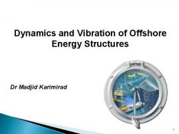
In previous work, we applied a wind lens lens to to VAWTs VAWTs and and examined examined the power augmentation effects using wind tunnel experiments [14–16]. In this study, we we investigated investigated the parameters of both configurations of a wind lens (i.e., flange width, diffuser open angle, diffuser length) and its location in the streamwise direction relative to the turbine. Power Power augmentation augmentation was was also also examined examined when when the configuration configuration of the open wind turbine (e.g., number of turbine blades, airfoil shape, and chord length) was changed. In addition, by varying the approaching wind speed, we investigated the effect of the Reynolds number on the power output of a VAWT VAWT when when combined combinedwith withaawind windlens. lens. 2. WindTunnel Tunnel Experiments Experiments 2. Wind The were conducted using the the large wind tunnel tunnel of of the The experiments experiments were conducted using large boundary-layer boundary-layer wind the Research Research Institute for Applied Mechanics, Kyushu University (Fukuoka, Japan). It has a measurement section of Institute for Applied Mechanics, Kyushu University (Fukuoka, Japan). It has a measurement section 15.0 m ˆ 3.6 m ˆ 2.0 m (length ˆ width ˆ height) and a maximum wind speed of 30 m/s. To avoid of 15.0 m × 3.6 m × 2.0 m (length × width × height) and a maximum wind speed of 30 m/s. To avoid blockage effects, we weremoved removedthe theceiling ceilingand andthe thewalls walls both sides within m the of the center of blockage effects, onon both sides within 6 m6 of center of the the measurement section. The approaching wind speeds U0inused in the experiments were 6 m/s measurement section. The approaching wind speeds U0 used the experiments were 6 m/s (Sections (Sections 3–5), and 6, 8, and 10 m/s (Section 6). 3–5), and 6, 8, and 10 m/s (Section 6). The were fabricated of wood. As As shown in Figure 1, ` is The blades blades and andarms armsofofthe thewind windturbines turbines were fabricated of wood. shown in Figure 1, the l is blade length (0.7 m), D is the diameter of rotation (0.7 m), and c is the chord length (mainly 0.15 or wt the blade length (0.7 m), Dwt is the diameter of rotation (0.7 m), and c is the chord length (mainly 0.15 0.1 m). The ratio of D /T = 0.19, where T is the width of the measurement section. The turbine w w = 0.19, where Tww is the width of the measurement section. The turbine or 0.1 m). The ratio ofwtDwt/T blades had linear shape in The shapes shapes of of the to the the blades had linear shape in the the vertical vertical direction. direction. The the airfoils airfoils mainly mainly conformed conformed to National Advisory Committee for Aeronautics (NACA) airfoils, although an arc-shaped airfoil was National Advisory Committee for Aeronautics (NACA) airfoils, although an arc-shaped airfoil was used Based on on the used for for the the experiments experiments considering considering the the effect effect of of the the Reynolds Reynolds number number (Section (Section 6). 6). Based the coordinate system shown in Figure 1, the center of the wind turbine was located above the floor of coordinate system shown in Figure 1, the center of the wind turbine was located above the floorthe of wind tunnel at z at = 0.7 the wind tunnel z = m. 0.7 m. A torque transducer N m) m) was was connected connected to to the the wind wind turbine turbine and and an an AC AC torque torque motor motor A torque transducer (rating: (rating: 55 N brake was set under it for the loading. See Table 1 for specifications on the transducer. We measured brake was set under it for the loading. See Table 1 for specifications on the transducer. We measured the torque Q Q (N (N m) m)with withan anaccuracy accuracyofof±0.2% ˘0.2% and rotational speed of the wind turbine under the torque and rotational speed n ofn the wind turbine under the the condition of gradually increasing the turbine load from zero. The calculated power outputs condition of gradually increasing the turbine load from zero. The calculated power outputs P (W) = P =Q ˆshown 2πn areasshown as performance Q (W) × 2πn are performance curves. curves.
Dwt
c
l
z y
x
Figure 1. Vertical-axis wind turbine used in the wind tunnel experiments. Figure 1. Vertical-axis wind turbine used in the wind tunnel experiments.
Energies 2016, 9, 406 Energies 2016, 9, 406
3 of 14 3 of 14
Table1. 1.Torque Torque transducer transducerand andAC ACservo-control servo-controlsystem. system. Table Device Manufacturer Device Manufacturer Torque detector ONO SOKKI Co. Ltd. ONO SOKKI Co. Ltd. Torque detector Torque converter (Kanagawa, Japan) (Kanagawa, Japan) Torque converter SANYO DENKI Co. Ltd. AC servo-control system SANYO DENKI Co. Ltd. (Tokyo, Japan) AC servo-control system (Tokyo, Japan)
Model Measurement Accuracy Model Measurement Accuracy SS-100 ±0.2% F.S SS-100 TS-2600 ˘0.2% F.S TS-2600 PY0A 150A PY0A 150A -
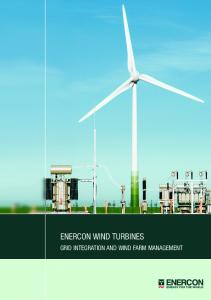
3. Application of a Wind Lens with a Flat-Panel-Type Diffuser 3. Application of a Wind Lens with a Flat-Panel-Type Diffuser 3.1. Configuration of the Wind Lens 3.1. Configuration of the Wind Lens As shown in Figure 2, the VAWT was installed with a wind lens that was symmetrical about the As shown in Figure 2, the VAWT was installed with a wind lens that was symmetrical about the direction of flow. The wind turbine had two blades (c = 0.15 m, airfoil: NACA0018) and the arms of the direction of flow. The wind turbine had two blades (c = 0.15 m, airfoil: NACA0018) and the arms of wind turbine held the blades at a distance of 0.4c m from the leading edge. The wind lens made of the wind turbine held the blades at a distance of 0.4c m from the leading edge. The wind lens made of aluminum pipes and polystyrene panels and the diffuser unit consisted of flat panels. In Figure 2a, pipes length and polystyrene panels andwidth the diffuser consisted of flat panels. In Figure 2a,(°), L is Laluminum is the diffuser (m), h is the flange (m), φunit is the semi-open angle of the diffuser ˝ ), D (=0.8 m) the diffuser length (m), h is the flange width (m), ϕ is the semi-open angle of the diffuser ( D (=0.8 m) is the distance between the two sides of the wind lens at the throat, and W (=1.79D m) is is the distance between the two thecovered wind lens the throat, and W in (=1.79D m) is direction the heighttoof the height of the wind lens. The sides wind of lens theat VAWT thoroughly the vertical the wind lens. The wind lens covered the VAWT thoroughly in the vertical direction to minimize the minimize the influence of three-dimensional flows around the wind lens (i.e., l = 0.7 m, W = 1.43 m, influence of three-dimensional flows windthe lens (i.e.,of`the = 0.7 m, W = 1.43 the center and the center of the wind turbine wasaround locatedthe above floor wind tunnel at m, z =and 0.7 m). of the wind turbine was located above the floor of the wind tunnel at z = 0.7 m).
y φ
Flow
o D
x W
Rotation
h L L
Flow (a) Plan view
(b) Photograph
Figure 2. 2. Configuration Configuration of wind lens is W); and (b)(b) in situ Figure of the the wind windlens: lens:(a) (a)plan planview view(the (theheight heightofofthe the wind lens is W); and in ˝ , h = 0.5D m). photograph (L = 1.14D m, ϕ = 10 situ photograph (L = 1.14D m, φ = 10°, h = 0.5D m).
3.2. Effect of Flange Width 3.2. Effect of Flange Width Figure 3 shows power coefficient curves against tip speed ratio λ. The power coefficient is defined Figure 3 shows power coefficient curves against tip speed ratio λ. The power coefficient is as Cp = P/(0.5 ρ¨ U0 3 ¨ A), where A (=` D ¨ m) is the profile of the rotor area in the streamwise direction. defined as Cp = P/(0.5 ρ·U03· A), where Awt(=l Dwt· m) is the profile of the rotor area in the streamwise The diffuser length L was 1.14D m, the semi-open angle ϕ was 20˝ , and the location of the wind lens direction. The diffuser length L was 1.14D m, the semi-open angle φ was 20°, and the location of the in the streamwise direction was aligned with the center of the wind turbine (x = 0 m). We compared wind lens in the streamwise direction was aligned with the center of the wind turbine (x = 0 m). We the power augmentation effects between h = 0.25D and h = 0.5D m. The results showed that a wind compared the power augmentation effects between h = 0.25D and h = 0.5D m. The results showed that lens with wide flanges was more effective than one with narrow flanges. Furthermore, the power a wind lens with wide flanges was more effective than one with narrow flanges. Furthermore, the augmentation with the wind lens was a factor of 2.6 times that of an open wind turbine. power augmentation with the wind lens was a factor of 2.6 times that of an open wind turbine.
Energies 2016, 9, 406 Energies Energies 2016, 2016, 9, 9, 406 406
4 of 14 44 of of 14 14
×2.6
Figure 3. Power coefficient C of wind wind turbines turbines with with and and without without wind lens vs. tip speed speed ratio ratio Figure 3. 3. Power Power coefficient coefficient C Cppp of without aaa wind wind lens lens vs. vs. tip ratio λλ λ Figure (diffuser length: 1.14D m). m). Refer to to Figure Figure 22 for for h, D, L, and φ. (diffuser (diffuserlength: length: LL L === 1.14D m). Refer for h, h, D, D, L, L, and and ϕ. φ.
3.3. Angle of Diffuser 3.3. 3.3. Effect Effect of of Open Open Angle Angle of of Diffuser Diffuser Figure shows power coefficient curves when the open angle of the Figure Figure 444 shows shows power power coefficient coefficient curves curves against against tip speed speed ratio λλ λ when when the the open open angle angle of of the the ˝ ˝ diffuser φ was varied from 5° to 20°. The diffuser length L was 1.14D m, the flange width h was diffuser diffuser ϕ φ was was varied varied from from 55° to to 20 20°.. The diffuser length L was 1.14D m, the flange width width hh was was 0.5D m, and the location of the wind lens in the streamwise direction was aligned with the center of 0.5D 0.5D m, m, and and the the location location of of the the wind wind lens lens in in the the streamwise streamwise direction direction was was aligned aligned with with the the center center of of the wind turbine (x = The results showed that the larger diffuser, the the wind turbine (x = 0 m). the semi-open angle of the diffuser, the the wind turbine (x = The results showed that the larger diffuser, the greater the increase of diffuser made it greater greater the the increase increase of of CC Cppp. Furthermore, the the increase in the semi-open angle of the the diffuser diffuser made made it it possible to generate higher power output over wider range of tip speed ratios. possible possible to to generate generate higher higherpower poweroutput outputover overaaawider widerrange rangeof oftip tipspeed speedratios. ratios.
Figure 4. Power coefficient C of wind turbines with and without wind lens vs. tip speed ratio Figure 4. 4. Power Power coefficient coefficient C Cppp of of wind wind turbines turbines with with and and without without aaa wind wind lens lens vs. vs. tip tip speed speed ratio ratio λλ λ Figure (diffuser length: L = 1.14D m). Refer to Figure 2 for h, D, and L. (diffuserlength: length: LL == 1.14D m). m). Refer to Figure 2 for for h, h, D, D, and and L. L. (diffuser
We also compared between wind lenses with the same projection area in the streamwise We also also compared compared CC Cppp between between wind wind lenses lenses with with the the same same projection projection area area in in the the streamwise streamwise We direction but different semi-open angles and flange widths (see Figure 5). The difference in was not direction but but different different semi-open semi-openangles anglesand andflange flangewidths widths(see (seeFigure Figure5). 5).The Thedifference differencein inCC Cppp was was not not direction large within the range of λ > 2 and for maximum C p ; however, in the range of λ ≤ 2, the wind lens with large within the range of λ > 2 and for maximum C p ; however, in the range of λ ≤ 2, the wind lens with large within the range of λ > 2 and for maximum Cp ; however, in the range of λ ď 2, the wind lens with the larger angle of the diffuser generated higher power output. Specifically, wind lenses with the larger larger semi-open semi-open generated higher power output. Specifically, windwind lenses with the semi-openangle angleofofthe thediffuser diffuser generated higher power output. Specifically, lenses larger semi-open angles of the diffuser can generate higher power output over a wider range of largerlarger semi-open angles of the can can generate higher power output overover a wider range of tip tip with semi-open angles ofdiffuser the diffuser generate higher power output a wider range of speed ratios when those wind lenses have the same projection area within the streamwise direction. speed ratios when those wind lenses have the same projection area within the streamwise direction. tip speed ratios when those wind lenses have the same projection area within the streamwise direction.
Energies Energies2016, 2016,9,9,406 406 Energies 2016, 9, 406
55ofof14 14 5 of 14
(a) (a)
(b) (b)
(c) (c)
Figure 5. (a) Power coefficient Cp of wind turbines with and without a wind lens vs. tip speed ratio λ Figure 5. (a) Power coefficient Cp of wind turbines with and without a wind lens vs. tip speed ratio λ Figure 5. (a) Power wind turbines vs. tip speed ratio λ p of (diffuser length: L =coefficient 1.14D m);C(b) plan view of the with windand lenswithout of type aA;wind and lens (c) plan view of the wind (diffuserlength: length: LL == 1.14D 1.14D m); m); (b) (b) plan plan view view of of the the wind wind lens lens of of type type A; A; and and (c) (c) plan plan view view of of the the wind wind (diffuser lens of type B. Refer to Figure 2 for h, D, and L. lens of of type type B. B. Refer Refer to to Figure Figure22for forh,h,D, D,and andL. L. lens
3.4. Effect of Diffuser Length 3.4. Effect Effect of of Diffuser Diffuser Length Length 3.4. The previous section confirmed the effectiveness of the semi-open angle of the diffuser on Cp. The previous previous section section confirmed confirmed the the effectiveness effectiveness of of the the semi-open semi-open angle angle of of the the diffuser diffuser on C Cpp.. The Making the diffuser length shorter without changing B (see Figure 6) creates a larger semi-openon angle. Making the the diffuser diffuser length length shorter without without changing B B (see Figure Figure 6) creates aa larger semi-open angle. Making createsm) larger semi-open Therefore, we configured ashorter wind lens withchanging half-length(see diffuser (L 6) = 0.57D and examined its angle. effect. Therefore, we configured a wind lens with half-length diffuser (L = 0.57D m) and examined its Therefore, configured a wind half-length diffuser (L =lens 0.57D m)a and examined its effect. effect. The flangewe width h was 0.5D m. lens The with results showed that a wind with larger semi-open angle, The flange flange width hh was was 0.5D 0.5D m. m. The The results results showed showed that that aa wind wind lens lens with with aa larger larger semi-open semi-open angle, The created bywidth shortening the length of the diffuser, could generate higher power output over aangle, wider created by shortening the length of the diffuser, could generate higher power output over aa wider wider created by shortening the length of the diffuser, could generate higher power output over range of tip speed ratios. Furthermore, the maximum Cp was also increased. range of of tip tip speed speed ratios. ratios. Furthermore, Furthermore, the the maximum maximum CCpp was was also also increased. increased. range
(a) (a)
(b) (b)
(c) (c)
Figure 6. (a) Power coefficient Cp of wind turbines with and without a wind lens vs. tip speed ratio λ Figure Figure 6. 6. (a) (a) Power Power coefficient coefficient CCpp of wind turbines with with and and without without aa wind wind lens lens vs. vs. tip tip speed speed ratio ratio λλ (flange width: h = 0.5D m); (b) plan view of the wind lens of type C; and (c) plan view of the wind lens (flange (flangewidth: width:hh== 0.5D 0.5D m); m); (b) (b) plan plan view view of of the the wind wind lens lens of of type type C; C; and and (c) (c) plan plan view view of of the the wind wind lens lens oftype typeD. D.Refer RefertotoFigure Figure22for forh,h,and andD. D. of of type D. Refer to Figure 2 for h, and D.
With consideration of higher power output, we examined the effect of φ, using a wind lens with With Withconsideration considerationof ofhigher higherpower poweroutput, output,we weexamined examinedthe theeffect effectof ofϕ, φ, using using aa wind wind lens lens with with short-type diffuser (L = 0.57D m). We varied the semi-open angle of the diffuser φ from 10° to 30°. ˝ to ˝. short-type 30 short-type diffuser diffuser (L (L == 0.57D m). We varied the semi-open angle of the diffuser ϕ φ from 10 10° 30°. Figure 7 shows the power coefficient curves against tip speed ratio λ. For the case of φ = ˝30°, Cp hits Figure ratio λ. λ. For thethe case of of ϕ= , CpChits a Figure 77shows showsthe thepower powercoefficient coefficientcurves curvesagainst againsttiptipspeed speed ratio For case φ 30 = 30°, p hits a peak and it underruns the value of Cp for the case of φ = 20°, except around the peak. This indicates ˝ , except peak and it underruns the value ofof CpCfor the a peak and it underruns the value p for thecase caseofofϕφ==20 20°, exceptaround aroundthe thepeak. peak. This This indicates indicates the existence of an optimum upper limit for the semi-open angle of the diffuser. the the existence existence of of an an optimum optimum upper upper limit limit for forthe thesemi-open semi-openangle angleof ofthe thediffuser. diffuser.
Energies 2016, 9, 406 Energies 2016, 9, 406 Energies 2016, 9, 406
6 of 14 6 of 14 6 of 14
Figure Power coefficientCC ofwind wind turbines turbines with with and ratio λ λ Figure 7. 7. Power coefficient and without withoutaawind windlens lensvs. vs.tiptipspeed speed ratio p ppof Figure 7. Power coefficient C of wind turbines with and without a wind lens vs. tip speed ratio λ (diffuser length: L = 0.57D m). Refer to Figure 2 for D, and L. (diffuser length: L= and L. L. (diffuser length: L =0.57D 0.57Dm). m).Refer Referto toFigure Figure 22 for for D, D, and
Effect Inlet 3.5.3.5. Effect of of thethe Inlet 3.5. Effect of the Inlet Figure 8 shows power coefficient curves against tip speed λ when the part inlet part (with Figure 8 shows power coefficient curves against tip speed ratioratio λ when the inlet venturi Figure 8 shows power coefficient curves against tip speed ratio λ when the inlet (with part (with venturi configuration) of the wind lens was removed. The diffuser length L was 0.57D m, the flange configuration) of the wind lenswind was lens removed. The diffuser length Llength was 0.57D the m, flange width h venturi configuration) of the was removed. The diffuser L wasm, 0.57D the flange hm, was 0.5D m, and the semi-open angle of theϕ diffuser φ 20°. Overall, its absence had little ˝ .was waswidth 0.5D and the semi-open angle of the diffuser was 20 Overall, its absence had little effect width h was 0.5D m, and the semi-open angle of the diffuser φ was 20°. Overall, its absence had littleon effect on the maximum C p, but the shrouded wind turbine without the inlet demonstrated higher theeffect maximum turbine without thewithout inlet demonstrated higher output only p , but the shrouded on theCmaximum Cp, but thewind shrouded wind turbine the inlet demonstrated higher output only within a narrow range of λ. Specifically, the inlet enhances power augmentation over a within a narrow rangeaof λ. Specifically, theSpecifically, inlet enhances power augmentation over a wider over rangea of output only within narrow range of λ. the inlet enhances power augmentation wider range of tip speed ratios. tipwider speedrange ratios.of tip speed ratios.
Figure 8. Effect of the inlet of the wind lens on power coefficient Cp. Figure8.8.Effect Effectofofthe theinlet inletof of the the wind wind lens p. . Figure lens on on power powercoefficient coefficientCC p
3.6. Effect of Wind Lens Location Effect Wind LensLocation Location 3.6.3.6. Effect of of Wind Lens The Venturi shape of a wind lens accelerates the wind at its throat [17]. Therefore, to generate The Venturi shape a wind lens accelerates wind at throat [17].Therefore, Therefore,totogenerate generate Venturi shape of of a wind lens accelerates thethe wind itsits throat [17]. theThe highest power output, the throat is the best location forat a horizontal-axis wind turbine. However,the the highest power output, the throat is the best location for a horizontal-axis wind turbine. However, highest power the throat is the best location for aand horizontal-axis wind turbine. However, the rotor of a output, VAWT extends in the streamwise direction, therefore consideration should be giventhe theof rotor of a VAWT extends instreamwise the streamwise direction, and therefore considerationshould shouldbe be given to rotor a VAWT extends in the direction, and therefore consideration to the determination of the optimum position of a VAWT within a wind lens. We examined thegiven effect todetermination the determination of optimum the optimum position a VAWT withinwind a wind lens.We Weexamined examined theeffect effect theof the position aofVAWT within lens. the location ofofthe wind lens relative toofthe position of thea VAWT in the streamwise the direction. of of the location of the wind lens relative to the position of the VAWT in the streamwise direction. theFigure location of the power wind lens relativecurves to theagainst positiontipofspeed the VAWT the streamwise 9 shows coefficient ratio λinwhen the locationdirection. of throat Figure of the 9 Figure 9 shows power coefficient curves against tip speed ratio λ when the location of throat of the shows power coefficient curves against tip speed ratio λ when the location of throat of the wind lens wind lens was moved from x = −Dwt/2 to x = Dwt/2 m. The diffuser length L was 1.14D m, the flange wind lens was moved from x = −Dwt/2 to x = Dwt/2 m. The diffuser length L was 1.14D m, the flange was moved from x =m, ´D x = Dwt /2angle m. The diffuser length L was 1.14D m, the flangethat width width h was 0.5D and thetosemi-open of the diffuser φ was 15°. The results showed to h wt /2 width h was 0.5D m, and the semi-open angle of the diffuser φ was 15°. The results showed that to generate highest power output, of the VAWTs (x˝ .= The 0) isresults the bestshowed locationthat for the throat was 0.5D m,the and the semi-open anglethe of center the diffuser ϕ was 15 to generate generate the highest power output, the center of the VAWTs (x = 0) is the best location for the throat the wind lens. For the of xof=the −DVAWTs wt/2 m, the Cp location was the for lowest. For the of theofhighest power output, thecase center (x =maximum 0) is the best the throat of case the wind of the wind lens. For the case of x = −Dwt/2 m, the maximum Cp was the lowest. For the case of lens. For the case of x = ´Dwt /2 m, the maximum Cp was the lowest. For the case of x = Dwt /2 m,
Energies 2016, 9, 406
7 of 14
Energies 2016, 9, 406
7 of 14
Energies 2016, 406 Cp showed an 9, increase in the maximum value, but it did not reach the value for the case 7ofof x14 = 0. x = Dwt/2 m, Cp showed an increase in the maximum value, but it did not reach the value for the case of The shape of the power coefficient curve became more peaked when the throat of the wind lens was xx == 0. The shape of the power coefficient became more when thethe throat offor thethe wind Dwt /2 m, Cp showed an increase in the curve maximum value, butpeaked it did not reach value caselens of located behind the wind turbine. ThisThis is similar to the curve ofofthe shrouded windturbine turbine with was located behind the power wind turbine. is similar to the curve the shrouded wind with no no x = 0. The shape of the coefficient curve became more peaked when the throat of the wind lens inlet.inlet. Based on this result, it is assumed that an inlet is inefficient when located behind a wind turbine. Based on this result, it is assumed that an inlet is inefficient when located behind a wind turbine.
was located behind the wind turbine. This is similar to the curve of the shrouded wind turbine with no inlet. Based on this result, it is assumed that an inlet is inefficient when located behind a wind turbine.
Figure 9. Power coefficient p of wind turbines vs. tip speed ratio λ (diffuser length, L = 1.14D m; Figure 9. Power coefficient CpCof wind turbines vs. tip speed ratio λ (diffuser length, L = 1.14D m; flange width, h = 0.5D m; semi-open angle diffuser, φ speed Referλto(diffuser 2length, for h, D, and L. m; Figure 9. Power coefficient C p of wind turbines vs. tip = 1.14D flange width, h = 0.5D m; semi-open angle ofofdiffuser, ϕ == 15°). 15˝ ).ratio Refer toFigure Figure 2 for h,L D, and L. flange width, h = 0.5D m; semi-open angle of diffuser, φ = 15°). Refer to Figure 2 for h, D, and L.
The transitions of maximum Cp for the various configurations of the wind lens with a VAWT are The transitions of maximum Cp for the various configurations of the wind lens with a VAWT The transitions of maximum p for the various the wind lenscenter with aof VAWT are summarized in Figure 10a. WhenCthe throat of the configurations wind lens wasoflocated at the the wind are summarized in Figure 10a. When the throat of the wind lens was located at the center of the summarized in Figure 10a. When the throat of the wind lens was located at the center of the wind turbine, larger semi-open angles of the diffuser led to an increase of Cpmax. When the throat of the wind turbine, larger semi-open angles ofdiffuser the to was an increase Cpmaxthe . When the throat turbine, semi-open of the ledtendency toled an increase of Cpmaxof . When throat ofsemithe wind lenslarger was behind the angles wind turbine, the diffuser same produced. Generally, larger of the wind lens was behind the wind turbine, the same tendency was produced. Generally, larger wind angles lens was the wind turbine, same tendency produced. wind Generally, open of behind the diffuser led to greaterthe acceleration of thewas approaching by thelarger windsemilens. semi-open angles of the diffuser led to greater acceleration of the approaching wind by the wind lens. open angles of the to was greater acceleration of theturbine, approaching by theangles wind of lens. When the throat of diffuser the windled lens in front of the wind larger wind semi-open the When the throat the wind of turbine, larger semi-open angles of the When the of the wind wasinwas infront front ofthe the wind wind turbine, larger semi-open of the diffuser ledthroat to of a decrease of lens Cplens maxwas . This suspected to be due to the widening of theangles gap between diffuser ledaand to athe decrease of Cp . Thiswas was suspected to totothe widening thethe gap between diffuser led to decrease of turbine Cp . This suspected to be bedue duewind the widening of between the diffuser wind through which the accelerated could flow.of Based ongap the above maxmax the diffuser and wind turbine through which the accelerated could Based on on thethe above results, the location for a windwhich lens inthe theaccelerated streamwisewind direction isflow. aligned with center the diffuser andoptimum the the wind turbine through wind could flow. Based above results, the optimum location for a wind lens in the streamwise direction is aligned with the center of the results, theVAWT. optimum location for a wind lens in the streamwise direction is aligned with the center of of the VAWT. the VAWT.
(a) (a)
(b) (b)
Figure 10. (a) Maximum power coefficient Cpmax of wind turbines vs. semi-open angle of the diffuser φ; Figure 10. (a) Maximum power coefficient Cpmax of wind turbines vs. semi-open angle of the diffuser φ;
(b) 10. Inferred flow whenpower the throat of the Cp wind lens is located in front of the wind turbine. Refer to Figure (a) Maximum coefficient max of wind turbines vs. semi-open angle of the diffuser (b) Inferred when the throat of the wind lens is located in front of the wind turbine. Refer to Figure 2 for flow h,flow D, when and L. the ϕ; (b) Inferred throat of the wind lens is located in front of the wind turbine. Refer to Figure 2 for h, D, and L. Figure 2 for h, D, and L. 4. Application of a Wind Lens with a Curved-Surface-Type Diffuser 4. Application of a Wind Lens with a Curved-Surface-Type Diffuser 4. Application of ainWind with a Curved-Surface-Type As shown FigureLens 7, the larger the semi-open angle ofDiffuser the diffuser becomes, the greater the As shown in Figure 7, the larger the semi-open angle of the diffuser becomes, the greater the increase of C p; however, Cp reaches a peak when the wind lens incorporates a flat-panel-type diffuser. As shown in Figure 7, the larger the semi-open angle of the diffuser becomes, the greater the increase of C p; however, Cp reaches a peak when the wind lens incorporates a flat-panel-type diffuser. Preventing this sluggishness might lead to further growth of the power output, and therefore we increase of C ; however, Cp reaches a peak the wind lens a flat-panel-type p this sluggishness Preventing might lead when to further growth of incorporates the power output, and thereforediffuser. we
Preventing this sluggishness might lead to further growth of the power output, and therefore we
Energies 2016, 9, 406
8 of 14
Energies 2016, 9, 406
8 of 14
Energies 2016, 9, 406
8 of 14
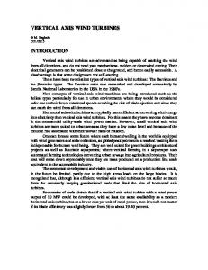
changed the diffuser to one with a curved surface, based on the expectation that the continuous changed the diffuser to one with a curved surface, based on the expectation that the continuous expansion of of thethe semi-open angle would prevent flowseparation. separation. expansion semi-open angle prevent flow changed the diffuser to one withwould a curved surface, based on the expectation that the continuous Figure shows the configuration of a wind lens a curved-surface-type diffuser. Figure11 11the shows the configuration a wind lens with awith curved-surface-type diffuser. The expansion of semi-open angle wouldof prevent flow separation. Theconfiguration configuration is based on the configuration of a wind lens with a flat-panel-type diffuser is shows based on configurationofofaawind wind lens lens with aa flat-panel-type diffuser for which Figure 11 thethe configuration curved-surface-type diffuser. The for ˝ and diffuser length L = 0.57D m. Shortening the width of the which the semi-open angle ϕ = 20 the semi-open angle φ = on 20°the andconfiguration diffuser length 0.57Dlens m. Shortening the width ofdiffuser the flanges configuration is based ofLa=wind with a flat-panel-type for from which hthe = 0.5D tohh== 0.5D 0.25D it possible broader of the diffuser exhaust. The wind flanges from tom 0.25D m makesfor it the possible forexpansion the expansion exhaust. semi-open angle φhmakes ==20° and diffuser length L = 0.57D m. broader Shortening the widthof ofthe thediffuser flanges from was made from wooden and acrylic panels. The dimensions D and W were hwind = 0.5D to hwas = 0.25D m makes it possible for theand broader expansion of theof diffuser exhaust. Thesame wind Thelens lens made from boards wooden boards acrylic panels. The dimensions of Dthe and W were forwas the case offrom the flat-panel-type diffuser. Furthermore, we dimensions used a wind turbine arms lens made wooden boards and acrylic panels.Furthermore, The D and W were theheld same theas same as for the case of the flat-panel-type diffuser. weof used a whose wind turbine whose the blades at a distance of 0.5c m from the leading edge, because Takahashi et al. [18] have shown that as for the case of the flat-panel-type diffuser. Furthermore, we used a wind turbine whose arms held arms held the blades at a distance of 0.5c m from the leading edge, because Takahashi et al. [18] have this configuration of a wind more efficient one Takahashi whose arms hold the blades atthat a the that blades at configuration a distance of 0.5c m fromisthe leading edge,than because et al. [18] have shown shown this ofturbine a wind turbine is more efficient than one whose arms hold the blades distance of 0.4c m from leading edge. The airfoil type was NACA0018 and chord length was a configuration athe wind turbine is more efficient armsthe hold at a this distance of 0.4c moffrom the leading edge. The airfoilthan typeone waswhose NACA0018 andthe theblades chord at length 0.15 m. wasdistance 0.15 m. of 0.4c m from the leading edge. The airfoil type was NACA0018 and the chord length was 0.15 m.
h=0.25D
Curved-surface-type diffuser
h=0.25D
Curved-surface-type diffuser φ=20°
φ=20° Flat-panel-type diffuser Flat-panel-type diffuser h=0.5D
h=0.5D (a)
(b)
(a)of the wind lens with a curved-surface-type diffuser: (b)(a) plan view and (b) Figure 11. Configuration Figure 11. Configuration of the wind lens with a curved-surface-type diffuser: (a) plan view and in situ photograph. Refer to Figure 2 for D. (a) Plan view; (b) Photograph. Figure 11. Configuration wind2lens curved-surface-type diffuser: (a) plan view and (b) (b) in situ photograph. Referoftothe Figure for with D. (a)a Plan view; (b) Photograph. in situ photograph. Refer to Figure 2 for D. (a) Plan view; (b) Photograph.
Figure 12 shows power coefficient curves against tip speed ratio λ. The shrouded wind turbines
Figure 12 shows curves against speed λ. The with a curved surfacepower diffusercoefficient demonstrated higher power tip output thanratio turbines with shrouded a flat-panel-wind Figure 12 shows power coefficient curves against tip speed ratio λ. The shrouded wind turbines turbines with a curved diffuser demonstrated power turbines with a type diffuser over thesurface entire range of tip speed ratios.higher The wind lensoutput with athan curved diffuser with a curved surface diffuser demonstrated higher power output than turbines with a flat-panelflat-panel-type over the entirebyrange of tip speed2.1 ratios. The wind withwind a curved diffuser demonstrateddiffuser power augmentation a factor of about compared withlens an open turbine. type diffuser over the entire range of tip speed ratios. The wind lens with a curved diffuser demonstrated augmentation a factor about 2.1 considered, compared VAWTs with anshrouded open wind turbine. According topower the above results for theby VAWTs andofwind lenses within demonstrated power augmentation by a factor of about 2.1 compared with an open wind turbine. a curved-surface-type diffuserfor demonstrate higher outputconsidered, and enhanced powershrouded augmentation According to the above results the VAWTs and power wind lenses VAWTs within a According to the above results for the VAWTs and wind lenses considered, VAWTs shrouded within over a wider range diffuser of tip speed ratios. curved-surface-type demonstrate higher power output and enhanced power augmentation a curved-surface-type diffuser demonstrate higher power output and enhanced power augmentation overover a wider range of tip speed ratios. a wider range of tip speed ratios.
Figure 12. Power coefficient Cp of wind turbines with and without a wind lens vs. tip speed ratio λ (curved-surface-type diffuser with flange width: h = 0.25D m). Refer to Figure 2 for h, D, and L. Figure Power coefficient p of wind turbines with and without a wind lens vs. tip speed ratio λ Figure 12. 12. Power coefficient CpCof wind turbines with and without a wind lens vs. tip speed ratio λ (curved-surface-type diffuser with flangewidth: width:hh== 0.25D 0.25D m). h, h, D,D, and L. L. (curved-surface-type diffuser with flange m). Refer RefertotoFigure Figure2 for 2 for and
Energies 2016, 9, 406
9 of 14
Energies 2016, 9, 406
9 of 14
5. Applicationof ofaaWind Wind Lens Lens to to Various Various Configurations Configurations of 5. Application of Wind Wind Turbines Turbines Sections Sections 33 and and 44 examined examined the the effects effects of of aa wind wind lens lens on on CCpp when when changing changing the the configuration configuration of of the wind lens and its location relative to the VAWT. This section compares the power outputs of an the wind lens and its location relative to the VAWT. This section compares the power outputs of an open wind lens lens when when changing changing the the number number of of turbine turbine blades, blades, open wind wind turbine turbine and and aa wind wind turbine turbine with with aa wind airfoil airfoil shape, shape, and and chord chord length. length. We We used used the the wind wind lens lens with with the the flat-panel-type flat-panel-type diffuser diffuser for for which which the the ˝. diffuser length L = 0.57D m, flange width h = 0.5D m, and semi-open angle of the diffuser ϕ = 20 diffuser length L = 0.57D m, flange width h = 0.5D m, and semi-open angle of the diffuser φ = 20°. 5.1. 5.1. Effect Effect of of Number Number of of Turbine Turbine Blades Blades Figure 13 shows showspower powercoefficient coefficientcurves curvesagainst against speed ratio λ when wind turbines Figure 13 tiptip speed ratio λ when wind turbines withwith two two and three blades were used. The airfoil type was NACA0018 and the chord length was 0.15The m. and three blades were used. The airfoil type was NACA0018 and the chord length was 0.15 m. The turbine two blades generated higher power output thanwind the wind turbine with openopen windwind turbine withwith two blades generated higher power output than the turbine with three three blades, and the maximum C was found within the higher range of the tip speed ratio for p blades, and the maximum Cp was found within the higher range of the tip speed ratio for the twothe two-bladed The shrouded turbines exhibited sametendencies, tendencies, although although the bladed turbine.turbine. The shrouded wind wind turbines exhibited thethe same the incorporation of the wind lens led to power augmentation by a factor of 1.9–2.1 compared incorporation of the wind lens led to power augmentation by a factor of 1.9–2.1 compared with with the the open open wind wind turbine. turbine.
Figure 13. power coefficient Cp ofCtwoand three-bladed wind turbines with and without Figure 13. Comparison Comparisonofof power coefficient p of two- and three-bladed wind turbines with and a wind lens vs. tip λ (wind L =lens: 1.14D m,1.14D h = 0.5D φ = 15°). 2 Figure for L, D, without a wind lensspeed vs. tipratio speed ratio λlens: (wind L= m, hm, = 0.5D m, ϕRefer = 15˝to). Figure Refer to 2 h, and φ.h, and ϕ. for L, D,
5.2. Effect of Turbine Turbine Blade Blade Thickness Thickness 5.2. shows power coefficient curves against tip speed ratio λλ when when the the airfoil airfoil of of the the wind wind Figure 14 shows turbine was was changed. changed. The types of airfoils used were NACA0012, NACA0018, NACA0024, The were NACA0012, NACA0018, NACA0024, and NACA0030. The Theblades bladesofofthese theseairfoils airfoils had different thicknesses. number of blades NACA0030. had different thicknesses. TheThe number of blades was was two,two, and andchord the chord length m. The results showed thicker turbine blades to the maximum the length was was 0.15 0.15 m. The results showed thatthat thicker turbine blades led led to the maximum Cp C p at lower tip speed ratios and that the wind turbine with the NACA0024 airfoil generated the at lower tip speed ratios and that the wind turbine with the NACA0024 airfoil generated the highest highestoutput. power Specifically, output. Specifically, theblades thickest blades do not always the highest power power the thickest do not always generate thegenerate highest power output, and output, and there is an optimum blade thickness for VAWTs. For the cases in which the wind lens there is an optimum blade thickness for VAWTs. For the cases in which the wind lens was incorporated was incorporated with the turbines, the in power output were produced, with the wind turbines, the wind same tendencies in same powertendencies output were produced, although there was although there was power augmentation a factor of 1.9–2.2 compared the open wind turbine. power augmentation by a factor of 1.9–2.2by compared with the open windwith turbine.
Energies 2016, 9, 406
10 of 14
Energies 2016, 9, 406 Energies 2016, 9, 406
10 of 14 10 of 14
Figure14. 14.Power Powercoefficient coefficientC of wind wind turbines turbines with with airfoils airfoilsof ofvarious variousthickness thicknesswith withand andwithout withoutaaa Figure of wind turbines with airfoils Figure 14. Power coefficient CCppp of of various thickness with and without ˝ wind lens vs. tip speed ratio λ (wind lens: L = 1.14D m, h = 0.5D m, φ = 15°). Refer to Figure 2 for L, L, D, D, wind 15 ). Refer to Figure Figure 22 for for L, D, wind lens lens vs. vs. tip tip speed speed ratio ratio λλ(wind (windlens: lens:LL== 1.14D 1.14D m, m, hh == 0.5D 0.5D m, m, ϕ φ= = 15°). h,and andϕ. φ. h, h, and φ.
5.3. 5.3. Effect Effect of ofChord ChordLength Lengthof ofTurbine TurbineBlades Blades 5.3. Effect of Chord Length of Turbine Blades Figure Figure15 15shows showspower powercoefficient coefficientcurves curvesagainst againsttip tipspeed speedratio ratioλλλwhen whenthe thechord chordlength lengthof ofthe the Figure 15 shows power coefficient curves against tip speed ratio when the chord length of the turbine blades was changed. The airfoil type was NACA0024, the number of blades was two, and the turbine blades was changed. The airfoil type was NACA0024, the number of blades was two, and the turbine blades was changed. The airfoil type was NACA0024, the number of blades was two, and the chord results between chordlength lengthwas was0.10 0.10or or0.15 0.15m. m.The Theresults resultsshowed showedlittle littledifference differencein interms termsof ofmaximum maximumCCCpppbetween between chord length was 0.10 or 0.15 m. The showed little difference in terms of maximum the two cases for an open wind turbine; the turbine with the shorter blades generated the maximum the two cases for an open wind turbine; the turbine with the shorter blades generated the maximum the two cases for an open wind turbine; the turbine with the shorter blades generated the maximum withinaaahigher higherrange rangeof oftip tipspeed speedratios ratiosthan thanthe theturbine turbinewith withlonger longerblades. blades.For Forthe thecases casesin inwhich which C within higher range tip speed ratios CCpppwithin of than the turbine with longer blades. For the cases in which thewind windlens lenswas wasincorporated incorporated with withthe thewind windturbines, turbines,the thesame sametendencies tendencies in inpower poweroutput outputwere were the the wind lens was incorporated with the wind turbines, the same tendencies in power output were produced, although there was power augmentation by a factor of 2.0 compared with the open wind produced, although there was power augmentation by a factor of 2.0 compared with the open wind produced, although there was power augmentation by a factor of 2.0 compared with the open wind turbine.Figures Figures13 13and and15 15indicate indicatethat that the turbine with the lower solidity generated the maximum turbine. the turbine with the lower solidity generated thethe maximum Cp turbine. Figures 13 and 15 indicate that the turbine with the lower solidity generated maximum within higher range of tip tip speed speed ratios. is same tendency as previous previous works [19,20]. within a higher range of tip speed ratios. It isItItais same tendency as previous works [19,20]. CCpp within aa higher range of ratios. aa same tendency as works [19,20].
Figure15. 15. Comparisonof of powercoefficient coefficient Cp ofwind windturbines turbineswith withdifferent differentchord chordlengths lengthswith withand and Figure Figure 15. Comparison Comparison ofpower power coefficientCpCof turbines with different chord lengths with p of wind without aa wind wind lens lens vs. vs. tip tip speed speed ratio ratio λλ (wind (wind lens: lens: LL == 1.14D 1.14D m, hh == 0.5D 0.5D m, m, φ φ == 15°). 15°). Refer˝to to Figure Figure 22 without and without a wind lens vs. tip speed ratio λ (wind lens: L = m, 1.14D m, h = 0.5D m, ϕRefer = 15 ). Refer to for L, D, h, and φ. for L, D, h, and φ.h, and ϕ. Figure 2 for L, D,
5.4. Effect Effect of ofNumber NumberofofTurbine TurbineBlades Bladesfor forCase Casewith withsame sameSolidity Solidity Turbine Blades for Case with same Solidity 5.4. Figure16 16shows showspower powercoefficient coefficientcurves curvesagainst against tip tipspeed speed ratio ratio λλλwhen whenthe thenumber numberof ofturbine turbine when the number of turbine Figure blades and chord lengths were changed but the solidity of the wind turbine remained the same. blades and chord lengths were changed but the solidity of the wind turbine remained remained the the same. same. Solidity σσis isdefined definedas asσσσ===(2 (2N¨ N· c)/Dwtwt,,,where where N is the number of blades. blades. For For the the case case where where N N == 2, 2, is defined as (2 N· c)/D Solidity c)/D Nis isthe the number number of of blades. For the case wt whereN c was 0.15 m and where N = 3, c was 0.1 m (σ = 0.86). The results showed little difference in terms of c was 0.15 m and where N = 3, c was 0.1 m (σ = 0.86). The results showed little difference in terms of maximum CCpp between between the the two two cases; cases; however, however, for for larger larger values values of of N, N, the the lower lower the the power power output output maximum
Energies 2016, 9, 406
11 of 14
c was 0.15 m and where N = 3, c was 0.1 m (σ = 0.86). The results showed little difference in terms Energies 2016, 9, 406 11 of 14 of maximum Cp between the two cases; however, for larger values of N, the lower the power output generated generated within within the the low low range range of of tip tip speed speed ratios. ratios. Specifically, Specifically, itit is is not not always always possible possible to to obtain obtain the the same power output when σ is constant. For the cases in which the wind lens was incorporated same power output when σ is constant. For the cases in which the wind lens was incorporated with with the the wind wind turbines, turbines, the the same same tendencies tendencies in in power power output output were were produced, produced, although although there there was was power power augmentation augmentation by by aa factor factor of of 2.0–2.1 2.0–2.1 compared compared with with the the open openwind windturbine. turbine.
Figure 16. 16. Comparison of power power coefficient coefficient C Cpp of and different different blade blade Figure Comparison of of wind wind turbines turbines with with same same solidity solidity and numbers with and without a wind lens vs. tip speed ratio λ (wind lens: L = 1.14D m, h = 0.5D m, numbers with and without a wind lens vs. λ (wind lens: ˝ φ = 15°). ϕ 15 ). Refer Refer to to Figure Figure 22 for for L, L, D, D, h, h, and and φ. ϕ.
Based on on the the above above results, results, the the incorporation incorporation of of aa wind wind lens lens demonstrates demonstrates power power augmentation augmentation Based equally irrespective of the configuration of the open wind turbine. Therefore, for maximum power equally irrespective of the configuration of the open wind turbine. Therefore, for maximum power output, itit is is important important for for aa wind wind lens lens to to be be incorporated incorporated with with an anefficient efficientopen openwind windturbine. turbine. output, 6. Effect 6. Effectof ofReynolds ReynoldsNumber Number on on Power Power Output Output The effect effect of of the the Reynolds Reynolds number on the power output of a VAWT with aa wind wind lens lens was was The VAWT with investigated by by varying varying the the approaching approaching wind wind speed speedUU00.. For For U U00 == 6, 6, 8, 8, and and 10 10m/s, m/s, the the Reynolds Reynolds investigated number, which chord length (c =(c0.15 m) ofm) theofturbine blades,blades, was 6.0was × 1046.0 , 8.0ˆ× 10 1044, number, which isisbased basedononthe the chord length = 0.15 the turbine 4 4 4 andˆ10.0 10 , respectively. types of airfoil used were a symmetric NACA0018 and anNACA0018 arc-shaped 8.0 10 ,× and 10.0 ˆ 10 , The respectively. The types of airfoil used were a symmetric NACA0018. The arc-shaped airfoil had a centerline of curvature of R = D wt /2 m. The curved-surfaceand an arc-shaped NACA0018. The arc-shaped airfoil had a centerline of curvature of R = Dwt /2 m. typecurved-surface-type diffuser was used with the wind lens. with the wind lens. The diffuser was used Figure 17 17 shows shows power power coefficient coefficient curves curves against against tip tip speed speed ratio ratio λ. λ. Higher Higher values values of of power power Figure output were were generated generated as as the the Reynolds Reynolds number number increased. increased. The open open wind wind turbine turbine with with arc-shaped arc-shaped output blades did not generate The value of of Cp blades generate as as much muchpower poweras asthe thewind windturbine turbinewith withsymmetric symmetricblades. blades. The value ofp the open wind turbine with arc-shaped blades hadhad highhigh dependency on the number. The C of the open wind turbine with arc-shaped blades dependency onReynolds the Reynolds number. Cp ofCthe open with symmetric blades reached a peak asathe Reynolds number increased. The the wind open turbine wind turbine with symmetric blades reached peak as the Reynolds number p of These results indicated existencethe of an upper limit the power can be derived increased. These resultsthe indicated existence of antoupper limit enhancement to the power that enhancement that from the increase of the Reynolds number. For the cases in which the wind lens was incorporated can be derived from the increase of the Reynolds number. For the cases in which the wind lens withincorporated the wind turbines, thewind same turbines, tendencies insame powertendencies output were produced, although there was was with the the in power output were produced, power augmentation by a augmentation factor of 2.1–2.2 thecompared open wind turbine. Furthermore, the although there was power bycompared a factor ofwith 2.1–2.2 with the open wind turbine. incorporationthe of the wind lens of enhanced effect of the Reynolds number on power augmentation. Furthermore, incorporation the windthe lens enhanced the effect of the Reynolds number on power For stable power output, wouldoutput, be preferable to incorporate a wind lens with an open wind turbine augmentation. For stableitpower it would be preferable to incorporate a wind lens with an for which effectfor of which the Reynolds number small. number is small. open windthe turbine the effect of the is Reynolds
Energies 2016, 9, 406 Energies 2016, 9, 406
12 of 14 12 of 14
(a)
(b)
Figure 17. Comparison of power coefficient Cp of wind turbines with various Reynolds numbers with Figure 17. Comparison of power coefficient Cp of wind turbines with various Reynolds numbers with and without without aa wind and wind lens lens vs. vs. tip tip speed speed ratio ratio λλ (wind (wind lens: lens:curved-surface-type curved-surface-type diffuser). diffuser). (a) (a) NACA0018, NACA0018, symmetric; (b) NACA0018, arc-shaped. symmetric; (b) NACA0018, arc-shaped.
7. Conclusions 7. Conclusions We incorporated incorporated aa wind wind lens lens in in aa VAWT VAWT and and examined examined its its effect effect on on power power augmentation augmentation using using We wind tunnel tunnel experiments. experiments. Various have been been applied applied to to horizontal-axis horizontal-axis wind wind wind Various styles styles of of wind wind lens lens have turbines and similar technology should be effective for VAWTs. turbines and similar technology should be effective for VAWTs. First, we we investigated investigated the the optimum optimum parameters parameters of of the the wind wind lens lens configuration. configuration. The wind lens lens First, The wind with a flat-panel-type diffuser demonstrated power augmentation by a factor of 2.0 compared with with a flat-panel-type diffuser demonstrated power augmentation by a factor of 2.0 compared with an open open wind wind turbine. turbine. The became, the greater the the power power an The larger larger the the semi-open semi-open angle angle of of the the diffuser diffuser became, the greater augmentation observed. diffuser made made it it augmentation observed. The The increase increase from from 5° 5˝ to to 20° 20˝ in in the the semi-open semi-open angle angle of of the the diffuser possible to generate a 30% high power output over a wider range of tip speed ratios. Furthermore, possible to generate a 30% high power output over a wider range of tip speed ratios. Furthermore, the larger the flange width became, became, the the greater the observed power augmentation. augmentation. For For aa constant the larger the flange width greater the observed power constant area area of projection in the streamwise direction, the wind lens with a larger semi-open angle of the diffuser of projection in the streamwise direction, the wind lens with a larger semi-open angle of the diffuser could generate generate higher wider range range of of tip tip speed speed ratios; ratios; however, however, an an optimum optimum could higher power power output output over over aa wider semi-open angle angle of of the the diffuser diffuser was was established. established. For flat-panel-type diffuser, recommended semi-open For the the flat-panel-type diffuser, aa recommended ˝ diffuser length is 0.5D, and its semi-open angle is 20°. The inlet enhanced the power augmentation diffuser length is 0.5D, and its semi-open angle is 20 . The inlet enhanced the power augmentation over over a wider range of tip speed ratios, and the best location for the wind lens in the streamwise a wider range of tip speed ratios, and the best location for the wind lens in the streamwise direction direction waswith aligned with the center of the The curved-surface-type was more was aligned the center of the VAWT. TheVAWT. curved-surface-type diffuser wasdiffuser more effective for effective for power augmentation than flat-panel-type diffusers. The wind lens with a curved-surfacepower augmentation than flat-panel-type diffusers. The wind lens with a curved-surface-type diffuser type diffuser demonstrated power augmentation by a factor of aboutwith 2.1 the compared withturbine. the open demonstrated power augmentation by a factor of about 2.1 compared open wind windThe turbine. power outputs of an open wind turbine and a wind turbine with a wind lens were compared The power the outputs of an openofwind turbine such and aas wind turbineofwith a wind lens were and compared when changing configuration the turbine, a number blades, airfoil shape, chord when changing the configuration of the turbine, the such as a numberof ofablades, airfoil shape, and chord length. Irrespective of the turbine configuration, incorporation wind lens demonstrated equal length. Irrespective of the turbine configuration, the incorporation of a wind lens demonstrated equal power augmentation. Therefore, power augmentation by the incorporation of a wind lens should be power augmentation. Therefore, augmentation incorporation of a wind lens should be possible, even as the efficiency of power the open wind turbinebyisthe improved. possible, ofnumber the openon wind improved. The even effectasofthe theefficiency Reynolds theturbine power is output of a VAWT with a wind lens was The effect of the Reynolds number on the power output of VAWT with a wind lens was investigated by changing the approaching wind speed. It would be apreferable to incorporate a wind investigated by changing the approaching wind speed. It would be preferable to incorporate a wind lens with an open wind turbine for which the effect of the Reynolds number is small, because the wind lens enhances with an open windon turbine which the effect of the Reynolds number is small, because the lens the effect powerfor augmentation. windThis lensstudy enhances the effect on power showed that a wind lensaugmentation. with a Venturi shape, curved diffuser, and shorter flanges This study showed that a wind lens withaagreater Venturi shape, curved diffuser, flanges (h = 0.25D m) was most effective in producing power augmentation. The and windshorter lens functions (h = 0.25D m) was most effective in producing a greater power augmentation. The wind lens functions optimally when aligned with the center of the VAWT. Furthermore, it was demonstrated that a optimally when center of the VAWT. Furthermore, it was for demonstrated that a twotwo-bladed windaligned turbinewith withthe NACA0024-type airfoils was most suitable the incorporation of a bladed wind turbine with NACA0024-type airfoils was most suitable for the incorporation of a wind wind lens to generate higher power output. lens to higher power output.studies that address the influence of the diffuser on power Wegenerate are undertaking additional We are undertaking additional studies that the address thebyinfluence of visualization the diffuser on augmentation. We are analyzing the flow around VAWT using flow andpower CFD, augmentation. We are analyzing the flow around the VAWT by using flow visualization and CFD, however, it is clear that the whole flow passing VAWT is concentrated and accelerated by flanged however, it is clear that the whole flow passing VAWT is concentrated and accelerated by flanged diffuser similarly to HAWT [2]. That is, VAWT possibly demonstrate power augmentation by a factor
Energies 2016, 9, 406
13 of 14
diffuser similarly to HAWT [2]. That is, VAWT possibly demonstrate power augmentation by a factor of 2–3 because the flange of wind lens generates a low-pressure region in the exit neighborhood of the diffuser by vortex formation and draws more mass flow to the wind turbine inside the diffuser shroud. Author Contributions: Koichi Watanabe and Shuhei Takahashi performed the experiments with supervision by Yuji Ohya. Koichi Watanabe analyzed the data. The manuscript was written by Koichi Watanabe and reviewed by Yuji Ohya. Conflicts of Interest: The authors declare no conflicts of interest.
Abbreviations The following abbreviations are used in this manuscript: VAWT NACA WT
vertical-axis wind turbine National Advisory Committee for Aeronautics wind turbine
References 1. 2. 3. 4. 5. 6. 7. 8. 9. 10. 11.
12.
13. 14.
15.
Ohya, Y.; Karasudani, T.; Sakurai, A.; Abe, K.; Inoue, M. Development of a shrouded wind turbine with a flanged diffuser. J. Wind Eng. Ind. Aerodyn. 2008, 96, 524–539. [CrossRef] Ohya, Y.; Karasudani, T. A shrouded wind turbine generating high output power with wind-lens technology. Energies 2010, 3, 634–649. [CrossRef] Gilbert, B.L.; Foreman, K.M. Experiments with a diffuser-augmented model wind turbine. J. Energy Resour. Technol. 1983, 105, 46–53. [CrossRef] Andrew, S.; Velissarios, K. Application of Circulation Controlled Blades for Vertical Axis Wind Turbines. Energies 2013, 6, 3744–3763. Travis, J.C.; Brian, H.D.; Zhen, X.H.; Bo, P.W. Aerodynamic Shape Optimization of a Vertical-Axis Wind Turbine Using Differential Evolution. ISRN Renew. Energy 2012, 2012, 1–16. Andrea, A.; Antonio, E.; Antonio, M.; Calogero, O.; Davide, T. 3D CFD Analysis of a Vertical Axis Wind Turbine. Energies 2015, 8, 3013–3033. Chao, L.; Songye, Z.; You-lin, X.; Yiqing, X. 2.5D Large Eddy Simulation of Vertical Axis Wind Turbine in High Angle of Attack Flow. Renew. Energy 2013, 51, 317–330. Rosario, L.; Stefano, M.; Michele, M. 2D CFD Modeling of H-Darrieus Wind Turbines Using a Transition Turbulence Model. Energy Procedia 2014, 45, 131–140. Sina, S.; Fernando, P.A. Large Eddy Simulation of Vertical Axis Wind Turbine Wakes. Energies 2014, 7, 890–912. Fujisawa, N.; Shibuya, S. Observations of Dynamic Stall on Darrieus Wind Turbine Blades. J. Wind Eng. Ind. Aerodyn. 2001, 89, 201–214. [CrossRef] Chong, W.T.; Naghavi, M.S.; Poh, S.C.; Mahlia, T.M.I.; Pan, K.C. Techno-economic analysis of a wind-solar hybrid renewable energy system with rainwater collection feature for urban high-rise application. Appl. Energy 2011, 88, 4067–4077. [CrossRef] Chong, W.T.; Fazlizan, A.; Poh, S.C.; Pan, K.C.; Hew, W.P.; Hsiao, F.B. The design, simulation testing of an urban vertical axis wind turbine with the Omni-direction guide vane. Appl. Energy 2013, 112, 601–609. [CrossRef] Daegyoum, K.; Morteza, G. Efficiency improvement of straight-bladed vertical-axis wind turbines with an upstream deflector. J. Wind Eng. Ind. Aerodyn. 2013, 115, 48–52. Watanabe, K.; Ohya, Y.; Karasudani, T.; Watanabe, K. Application of collection-acceleration device of wind to VAWT. In Proceedings of the Japan Wind Energy Symposium, Tokyo, Japan, 20 November 2004; Volume 26, pp. 147–150. (In Japanese) Takahashi, S.; Ohya, Y.; Karasudani, T.; Watanabe, K. Numerical and experimental studies of Airfoils suitable for Vertical axis wind turbines and an application of wind-energy collecting structure for higher performance. In Proceedings of the Fourth International Symposium on Computational Wind Engineering (CWE 2006), Yokohama, Japan, 16–19 July 2006; pp. 327–330.
Energies 2016, 9, 406
16.
17.
18.
19. 20.
14 of 14
Watanabe, K.; Ohya, Y.; Karasudani, T. Development of a high-performance Vertical axis wind turbine by a drive. In Proceedings of the National Symposium on Wind Engineering, Tokyo, Japan, 1–3 December 2010; pp. 239–244. (In Japanese) Ohya, Y.; Uchida, T.; Karasudani, T.; Hasegawa, M.; Kume, H. Numerical Studies of Flow around a Wind Turbine Equipped with a Flanged-Diffuser Shroud Using an Actuator-Disk Model. Wind Eng. 2012, 36, 455–472. [CrossRef] Takahashi, S.; Hamada, J.; Ohya, Y.; Karasudani, T. Numerical and experimental studies of Airfoils suitable for Vertical axis wind turbines and an application of wind-energy collecting structure. In Proceedings of the National Symposium on Wind Engineering, Tokyo, Japan, 29 November–1 December 2006; pp. 169–174. (In Japanese) Seki, K.; Otani, I. Performance of Straight Blade, Non-Articulated Vertical Axis Wind Turbine. J. JSES 1990, 16, 31–38. (In Japanese) Okubayashi, T.; Kage, K.; Ishimatsu, K.; Hamakawa, H.; Date, H. Experimental Study of Darrieus Wind Turbine; Oita University: Oita, Japan, 1996; Volume 33, pp. 17–22. (In Japanese) © 2016 by the authors; licensee MDPI, Basel, Switzerland. This article is an open access article distributed under the terms and conditions of the Creative Commons Attribution (CC-BY) license (http://creativecommons.org/licenses/by/4.0/).


![Cost of wind turbines [PDF]](https://m.moam.info/img/260x300/cost-of-wind-turbines-pdf_647d40d2098a9edb6d8b4576.jpg)