Proceedings of the World Congress on Engineering and Computer Science 2009 Vol I WCECS 2009, October 20-22, 2009, San Francisco, USA
Application of Model Detection Techniques to Health Monitoring for the Electrical Network of More Electric Aircraft Y. Ji Abstract— In this paper, a health monitoring problem for the electrical network of more electric aircraft is addressed. To undertake the health monitoring task, the multi-model detection technique is applied. Multi-model based approach associates to each health status a corresponding linear time invariant model, which is derived by adjusting appropriately the nonfaulty system model to a particular fault situation. The original health monitoring problem can be therefore formulated as a model detection problem. Besides the introduction of the theoretical preliminary of the multi-model based approach, the computer-aided design process, right-sized modelling and realtime simulation based validation for residual generator with Dymola and Matlab are also discussed. Health monitoring for an input filter of an DC motor drive serves as an application case to illustrate the proposed scheme. The designed residual generators are validated on the original nonlinear system with time-domain simulation.
I. INTRODUCTION Compared with the conventional power distribution network, the more electric aircraft architecture will demonstrate a significant weight decrease, reduced maintenance requirements, increased reliability and passenger comfort [1]. However, up to now, the early fault diagnosis and localization of faulty units in the electrical network of power by wire systems with a dramatically increased number of electrical components and equipments is an unsolved problem. In contrast to the present scenario of aircraft maintenance where a centre maintenance computer on board will receive failure information of the corresponding component just after its fail, the health management system in a more intelligent manner using modern fault diagnosis techniques shall be applied in the future aircraft to achieve more cost benefit, more flight reliability, decreased flight delay and more accurate information for ground maintenance after landing. Reviewing the considerable development of fault diagnosis techniques and many successful applications attached to them in the last time [2], [3], power systems seem to be a real hard challenge for the available fault diagnosis techniques. In spite of a few applications of neural networks for fault detection in power systems [4], the application of analytical model-based fault detection of power systems is just in the beginning phase. With the help of more accurate modelling of power systems and embedded microprocessors in digital controllers of power distribution systems within more electric This work is being conducted in the frame of the MOET project (More Open Electrical Technologies), a FP6 European Integrated Project. http://www.moetproject.eu Y. Ji and J. Bals are with Department of System Dynamics and Control, Institute of Robotics and Mechatronics, German Aerospace Center, Muenchnerstr. 20, Wessling, Germany
[email protected]
ISBN:978-988-17012-6-8
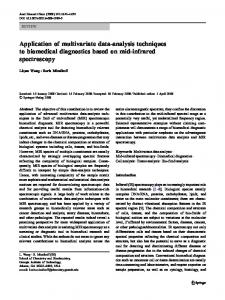
J. Bals aircraft, an unprecedented affordable opportunity can be provided for health monitoring and fault diagnosis using modelbased fault diagnosis techniques. To the best knowledge of the author in literature, few studies for health monitoring of power systems using multi-model based approach have been given before. Besides the introduction of the theory of multi-model based approach and its feasibility to solve the health monitoring problem, the experiences dealing with the troubles arising at the practical implementation of residual generator design such as computer-aided trimming, validation with simulation and minimal realization of the residual generator are also discussed. In the presented study case, a high voltage direct current (HVDC) architecture of more electric aircraft power system is considered, which contains a main generation unit-variable frequency generator (VFG), a 18-pulse autotransformer rectifier unit (ATRU), numerous electrical loads including an electro-mechanical actuator (EMA), a buck converter connected with low voltage loads depicted in Fig. 1. The health monitoring for the input filter of the EMA in the HVDC architecture has been performed to illustrate the proposed approach.
DC Mainbus
Input Filter EMA HV loads
ATRU VFG LV loads
Buck Converter
Fig. 1.
A HVDC architecture of more electric aircraft
II. T HEORETICAL PRELIMINARY OF HEALTH MONITORING USING MODEL DETECTION TECHNIQUE A. Model-based fault detection technologies Since each health level of a component can be interpreted with a specific fault situation in a system, the health monitoring can be redefined as a fault detection and isolation problem. A fault represents a change of the normal functioning of a system due to an unexpected event (e.g. aging of a component). In safety critical technical systems, a fault must be detected and diagnosed as early as possible to prevent any serious consequence. For this purpose, a fault diagnosis system can be used, which processes the measurable signals Y (t), U(t) and produces information on the fault occurrence
WCECS 2009
Proceedings of the World Congress on Engineering and Computer Science 2009 Vol I WCECS 2009, October 20-22, 2009, San Francisco, USA and localization. The main component of the fault diagnosis system is the residual generator, which produces the residual signals R(t) using the available measurements Y (t) and the known values of control inputs U(t) in the form · ¸ Y (t) R(t) = Q(t) (1) U(t) The residual generator is implemented on-line and generates the values of residuals in real time, which are then used to decide on the absence or presence of faults. For decision making, the residuals are further processed to obtain the evaluation signal. Traditional fault detection as well as isolation technologies, unknown-input observers, parity space, principle component analysis, H2 and H∞ optimal filter synthesis techniques can be mentioned. Among them the model based fault detection technique including diagnostic observer and parity space can be concluded to a unifying paradigm - nullspace based approach [8]. B. Modelling of a system with fault A main non-trivial task to be fulfilled before solving health monitoring problem is the development of adequate models, which fit into the available design methodologies. The multi-model based approach associates to each health status i.e. fault a corresponding model, which is derived by adjusting appropriately the non-faulty system model to a particular fault situation. A collection of individual models, where each model corresponds to a specific health status. The health monitoring is becoming a model detection problem. Considering the multi-model linear time-invariant systems described by input-output transfer functions (i)
(i)
y(i) (λ ) = Gu (λ )u(i) (λ ) + Gd (λ )d (i) (λ ) i ∈ [0, N] y(i) (λ ),
u(i) (λ ),
(2)
d (i) (λ )
are Laplace or Zwhere the vector Transformed vectors of ith system output y(t), control input (i) (i) vector u(t), and disturbance vector d(t). Gu (λ ) and Gd (λ ) are the transfer function matrices from the corresponding plant inputs to outputs. Assuming that all models are controlled with the same control inputs, the disturbance inputs can be different for each component model. The state-space realizations corresponding to the multi-model in (1) are in the form: (i)
(i)
(i)
(i)
λ x(i) (t) = A(i) x(i) (t) + Bu u(t) + Bd d(t) y(i) (t) = C(i) x(i) (t) + Du u(t) + Dd d(t)
(3)
where x(i) (t) is the state vector of the ith system. x(i) (t)and x( j) (t) have generally different dimensions for i 6= j. The fault-free system can be defined by the model with index i = 0. The above description of the faults is a very general way to account for all health statuses. Let θ be a parameter vector, whose components are model parameter which characterize different fault situations, the system model depending on θ can be described with y(λ ) = Gu (λ , θ )u(λ ) + Gd (λ , θ )d(λ )
(4)
Let θ (i) , i ∈ [0, N] be set of values, which characterize the normal operation without fault for θ (0) and the ith faulty
ISBN:978-988-17012-6-8
situations for θ = θ (i) . The multi-model defined in (2) can be represented as (i)
Gu (λ ) = Gu (λ , θ (i) ) (i)
Gd (λ ) = Gu (λ , θ (i) )
(5)
Assuming that the state-space realization corresponding to (3) has the form:
λ x(t) = A(θ )x(t) + Bu (θ )u(t) + Bd (θ )d(t) y(t) = C(θ )x(t) + Du (θ )u(t) + Dd (θ )d(t)
(6) (i)
The (3) can be defined by setting A(i) = A(θ (i) ), Bu = Bu (θ (i) ), C(i) = C(θ (i) ),· · · . In the practical applications e.g. an electrical network, the underlying system model is a nonlinear state-space model, which depends explicitly on the parameters. A linearized parametric model of the form in (6) is usually not available. A multi-model with matrices defined in (6) can be easily achieved using repeated linearization of the underlying nonlinear model for the selected values of the parameter θ (i) on the corresponding operation point at steady state [5]. C. Algorithm for solving the model identification based fault detection problem Assuming that N + 1 models describe the normal and faulty systems. ith model with i ∈ [0, N] is specified in the input-output form (2), where the model with index 0 represents the model without faults. The model detection problem can be formulated as follows: determine a bank of N + 1 stable and proper scalar output residual generators ¸ · z(λ ) i ∈ [0, N] (7) r(i) (λ ) = Q(i) (λ ) u(λ ) such as • r (i) (t) = 0 when z(t) = y(i) (t) • r (i) (t) 6= 0 when z(t) = y( j) (t) for i 6= j • all residual signals r (i) (t) are asymptotically bounded The formulation of the model detection problem allows an easy detection of the ”actual” model by simply looking for the residual signal with the smallest magnitude. The requirements formulated for the model detection problem can be easily expressed in equivalent algebraic design conditions for each of the N + 1 residual generators. The first condition is equivalent to determine each detector Q(i) (λ ), so that · (i) ¸ (i) (8) Q(i) (λ ) Gu (λ ) Gd (λ ) = 0 I 0 The second condition enforces the unambiguous detection of the ith model by additionally requiring that · ( j) ¸ ( j) (i, j) G ( λ ) G ( λ ) (i) u d 6= 0, when i 6= j R f (λ ) := Q (λ ) I 0 (9) (i, j) Subtracting (8) from (9), R f (λ ) can be interpreted as a weighted measure of the distance between the ith and jth model. It follows that the ith detector will produce a residual signal, whose amplitude depends on the difference between
WCECS 2009
Proceedings of the World Congress on Engineering and Computer Science 2009 Vol I WCECS 2009, October 20-22, 2009, San Francisco, USA the outputs of the actual model and those of the ith model. To fulfil the third requirement, each detector Q(i) (λ ) must (i, j) ensure that all R f (λ ) are stable transfer function matrices. If the model detection problem is solvable, each residual generation filter Q(i) (λ ) can be computed as a scalar output filter lying in the left nullspace of the transfer function matrix G(i) λ with · (i) ¸ (i) G ( λ ) G ( λ ) (i) u d (10) G λ := I 0 A global detector band can be built by stacking the N+1 scalar output residual generators as £ ¤T (11) Q(λ ) := Q(0) (λ ) Q(1) (λ ) · · · Q(N) (λ ) D. Fault isolation using structured residuals Let Q(λ ) be a given detector and let R f (λ ) be the corresponding transfer matrix from ith model to jth residual signal. Denoting the (i, j) entry of R f (λ ) as R f ,i j (λ ) , the fault signature matrix S can be defined with the (i, j) entry - Si j given by • • •
Si j = 1 if R f ,i j (λs ) 6= 0 Si j = −1 if R f ,i j (λs ) = 0 and R f ,i j (λ ) 6= 0 Si j = 0 if R f ,i j (λs ) = 0
E. Residual evaluation and decision making Generally, the residual signal can not provide enough information needed for the determination of model detection or fault detection. In this situation, the residual evaluator is usually needed to generate an evaluation signal Θ(t), which is an approximate measure of the residual signal energy (e.g. of the 2-norm). The evaluation signal can be generated by Z t t−T
r2 (τ )d τ
(12)
where the parameters α and β allow a desired weighting between instantaneous and long-term measures, T defines the duration of observation windows [6]. The decision making function has a binary output d = 0 or d = 1 , which is computed with the residual evaluation signal in such manner that Θi (t) ≥ Jth ⇒ di (t) = 1 Θi (t) < Jth ⇒ di (t) = 0
(13)
where Jth is a threshold. In the case of model detection the signal d(i) (t) is called model index, which indicates the best fitting model to the plant i.e. the present health status or fault situation.
ISBN:978-988-17012-6-8
modelling level behavioral level functional level linearized level
utilization power quality, validation of fault detection prerequisite of linearization stability analysis, design of fault detector
III. D ESIGN PROCESS OF RESIDUAL GENERATOR A main task to solve the health monitoring problem using multi-model based approach is the design of a residual generator. The main procedures of the design process are: • appropriately modelling of systems with faults • linearization of the original nonlinear systems after trimming • synthesis of the residual filter bank • design of the residual evaluator, if required • design of the decision maker i.e. setting threshold, if required The tool chain for the design of a residual generator in the presented work is depicted in Fig. 2 Dymola-Modelica
where λs = 0 for a continuous-time system and λs 6= 0 for a discrete-time system. If Si j = 1 , the model j is strongly detectable in residual i. If Si j 6= 1 the model j is weakly detectable in residual i. The model j is decoupled and not detectable from residual i , if Si j = 0. Therefore, considering the conditions of residual filter in section II-C, only entries in the diagonal of signature matrix are desired to be zero.
Θ(t) = α r2 (t) + β
TABLE I D ESCRIPTION OF SYSTEM LEVEL AND UTILIZATION
Matlab FDI Toolbox
1. Modelling of system with faults 2. Trimming and Linearization
Fig. 2.
LTI Model
Dymola-Modelica
1. Synthesis of residual filter 1. Implementation of residual filter residual filter 2. Design of residual 2. Validation of residual evaluator filter
Road map and tool chain for health monitoring
A. Right-sized modelling with Dymola For a different objective, the system shall be adequately modelled at various levels to fulfil the different requirements. A system model at behavioural level is used for the assessment of the power quality, where the high frequency effect from switching is taken into account. For small signal stability analysis, it is necessary to extract the so-called averaged model from the original behavioural system. At the functional level, the switching effect is ignored and the transient performance is presented by appropriately averaging the states of switching with duty time [11]. Because the averaged models are often nonlinear systems, linearized models at the operation point are needed to be able to apply linear system technique such as nullspace based fault detector design and eigenvalue based stability study (see Tab. I). With the advanced modelling technique with Dymola 1 , a complex system model can be conveniently switched between different model levels [7]. B. Computer-aided trimming and linearization The average models at the functional level mentioned above are normally nonlinear systems, which can be described with x˙ = f(x, u) y = g(x, u)
(14)
1 www.dynasim.com
WCECS 2009
Proceedings of the World Congress on Engineering and Computer Science 2009 Vol I WCECS 2009, October 20-22, 2009, San Francisco, USA where x, u, y are state, input and output vectors of a nonlinear system and f, g are nonlinear functions. To be able to apply the multi-model based fault detection approach, linear time invariant presentation of each faulty system is required. The presence of the severe faults can shift the operating condition drastically, the linearization of each average faulty system must therefore be carried out at the operating point of each fault situation. Define xi∗ , ui∗ , yi∗ as the operating point of ith faulty system, the linear time invariant system presenting the faulty model can be achieved by
∂ f(i) ∂ f(i) | (i) ∆x(i) + (i) | (i) ∆u(i) (i) x ∗ ∂x ∂ u u∗ (i) ∂g ∂ g(i) (i) | + | (i) ∆u(i) (15) ∆y(i) = (i) ∆x ∂ x(i) x∗ ∂ u(i) u∗ Trimming and linearization can be easily done with the help of the advanced initialization and linearization features of Dymola. Trimming of a model can either be done by initializing steady state condition at the beginning of the simulation or importing a selected operating point from previously simulated result. Linearization at the desired operating point can be subsequently computed by Dymola and exported to Matlab as linear time invariant (LTI) system object. ∆˙x(i)
=
operating points before connecting them to the corresponding residual generators. IV. H EALTH MONITORING FOR THE INPUT OF AN E LECTRO -M ECHANICAL ACTUATOR - AN APPLICATION CASE
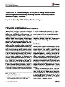
In the present HVDC architecture, electro-mechanical actuators are connected with DC link network, where DC/AC inverter is used to tightly regulate the motor current waveforms. Besides the benefits on this architecture such as full decoupling between turbine speed and load speed and increased motor robustness regarding preventing overcorrects, mostly perfect regulation has also the disadvantage that it makes the motor drive appear to be a constant power load which has a negative impedance at low frequencies [12]. Considering the highly simplified model of the motor drive with an input filter in Fig. 3, where L f , R f , C f are inductor, resistor and capacitor of input filter and P∗ is the motor load power at steady state, the impedance Zinv of motor by linearizing the input current idc regarding the input voltage Vdc can be described by Zinv = −
C. Toolbox for design of fault detection residual generator The fault detection and isolation toolbox for Matlab (FDI) developed by DLR provides a comprehensive set of high level m functions to support the design of residual generation filters using reliable numerical algorithms [9]. In the toolbox, a fairly complete collection of methods, solving various fault detection problem have several common appealing properties: • applicable to both standard and descriptor system • appropriate filter dynamics specification • least-order filter design The reason for the interest in the low and least order property of the residual generator is primarily that the dependency of a residual generator on the model should be as little as possible. A low order usually implies that only a small part of the model is utilized for the residual generator design. This means that few model errors will affect the residual signal, since all parts of the model have errors such as modelling error and linearization error. The further advantages of low order residual generators are easier implementation and less on-line computational burden [10]. D. Validation of residual generator To check if the designed residual generator fulfils all predefined conditions and specifications, Dymola provides a suitable platform to undertake the validation by real time simulation and user interactive toolbox, where each fault situation can be used to the original fault free system when simulation running. Normally, either average model or behavioural model can be utilized for a preliminary validation of a residual generator. Since the residual generator is only valid for small signal systems, the accessible system inputs and outputs must be firstly subtracted by steady state
ISBN:978-988-17012-6-8
P∗ ∆Vdc ∗2 Vdc
(16)
Due to the negative impedance, the system can become instable with an inadequate or degraded input filter. Using the eigenvalue of the linearized model of the electro-mechanical actuator, the necessary condition (17) for the stability of the system can be easily derived with Rf P∗ > ∗2 Lf C f Vdc
(17)
When the motor power P∗ keeps being constant, a degraded capacitor with decreased value can destabilize the system the motor and power supply. Therefore, the function of the input filter before the DC/AC inverter within electro-mechanical actuator is twofold: • •
power quality guarantee of HVDC main bus with regards to voltage and current harmonics stabilization of DC link network
Considering the significant cost benefit, aluminium electrolytic capacitor is proposed to be used for the input filter. However, using aluminium capacitor for the input filter has an inherent disadvantage, that the DC network becomes more fragile concerning the possible capacitor failure due to aging, manufacturing defect, ware-out faults and so on [13], Health monitoring of the capacitor in the input filter is therefore a new importance arising with HVDC network architecture of more electric aircraft in spite of an optimal predesign regarding the system stability [14]. Early detection of fault on the capacitor used in the input filter would allow preventive adverse fail and maintenance to be performed, and provide sufficient time for the controlled shutdown of the process, thereby reducing the costs of outage-time and repairs.
WCECS 2009
Proceedings of the World Congress on Engineering and Computer Science 2009 Vol I WCECS 2009, October 20-22, 2009, San Francisco, USA is
Lf
Fig. 3.
idc Cf
vsource
d dt
Rf
Z inv
v dc
Value 3.24e−6 Henry 2e−3 Ohm 420e−6 Farad 4028 Watt
EMA
+
-
+
VS_l=275
ground
VS_u=275
inertia
V... J=0.00095 LoadTorque
SpeedD
-
activ...
d dt
µ
∆is ∆Vdc
yr3
A. Modelling of the health status To undertake the health monitoring for the input filter of an EMA, a 2nd order Butterworth type filter and a DC motor drive are firstly modelled in Dymola (see Fig. 4). At steady state, the EMA can be looked as a constant power load with power P∗ . Since a degraded capacitor usually exhibits a Input Filter
yr2
TABLE II PARAMETERS IN THE INPUT FILTER OF THE EMA Description filter inductance filter resistance filter capacitance steady state motor power
∆is ∆Vdc
P* vdc
Highly simplified DC motor model with input filter
Parameter Lf Rf Cf P∗
µ
o...
true
· ¸µ ¶ µ ¶ −616.3 −9629 ∆is 9.4 = + ur2 6400 2.76 ∆vdc 0 µ ¶ £ ¤ ∆is = 0 −14.2 (19) ∆Vdc · ¸µ ¶ µ ¶ −616.3 −1.9e4 ∆is 18.8 = + ur3 ∆vdc 0 3.2e4 27.6 µ ¶ £ ¤ ∆is = 0 −14.2 (20) ∆Vdc
B. Simulation results The residual generator filter Q(s) for the multi-models in (18)-(20) is derived with FDI toolbox, which is written in (21). 2 +3.48e3 s+3.48e7 4.8e5 − 5.65s − 2 2 6 2 2 6 s +6.16e s+6.16e s +6.16e s+6.16e 5.65s 2 +3.46e3 s+3.48e7 1.13e−13 s+4.8e5 (21) Q(s) = − − 2 2 6 s +6.13e s+6.16e s2 +6.13e2 s+6.16e6 2 +1e3 s+1.05e9 1.46e5 − 1.72s − s2 +5.88e 2 s+6.16e6 s2 +5.88e2 s+6.16e8 The conducted signature matrix 0 −1 −1 S = −1 0 −1 −1 −1 0
(22)
indicates, that the LTI models G1 , G2 , G3 corresponding the predefined health statuses of the capacitor in the input filter are only weakly detectable with the residual generators in (21). It means, that the residual signal will disappear at steady state. To solve this weakly detectable problem, a virtual test signal such as
ε (t) = 0.01sin(20000π t) Fig. 4.
Modelling of an EMA with its input filter in Dymola
decreased capacitance value, the health statuses of input filter can be modelled by assigning the capacitor with different capacitance values. For the sake of simple illustration, three health statuses hi , i ∈ (1, 2, 3) of the input filter have been defined by setting the capacitor in input filter such as • h1 : C f = 5e−2 Farad, nominal system • h2 : C f = 5e−3 Farad, degraded degree I • h3 : C f = 5e−4 Farad, degraded degree II Certainly, the proposed health monitoring scheme is also capable to deal with more degraded degrees. The capacitor in the input filter with degraded degree II is considered as a very critical situation i.e. the stability boundary of the system. The capacitor in the input filter shall be immediately exchanged when degrade degree II arises. Denoting the DC main bus voltage Vsource as the input ur and the output current idc of the input filter as the output yr of a LTI system, which are assumed as accessible, with the parameters in Tab. II, the different health statuses defined above can be described by following three LTI systems G1 , G2 , G3 in (18)-(20). µ ¶ · ¸µ ¶ µ ¶ d ∆is −616.3 −2407 ∆is 4.7 = + ur1 2560 .276 ∆vdc 0 dt ∆Vdc µ ¶ £ ¤ ∆is (18) yr1 = 0 −7.1 ∆Vdc
ISBN:978-988-17012-6-8
(23)
has been introduced, which is added on the input ur of the residual geneartor. The simulation results of the residual signals are plotted in Fig. 5. In order to explicitly undertake a decision-making, a residual evaluator defined in (12) is applied, where α = 0, β = 2 and T = 0.05. The residual evaluator signals are showed in Fig. 6. Setting the threshold Jth = 1, the decision-making signals d(i) (t) defined in (13) can be showed in Fig. 7. Finally, the present health status of the capacitor in the input filter of the EMA denoted with h∗ can be determined by h∗ = hi , when di (t) = 0 i ∈ 1, 2, 3
(24)
As validation scenario, the degraded degree I and the degraded degree II of the capacitor have been activated at 3 second and 4.5 second, respectively. The Fig. 7 shows, that the decision-making signals has correctly determined the present health status with a time delay about 0.1 second, which will be allowed for a long-term health monitoring process. V. C ONCLUSION AND OUTLOOK A. Conclusion Concerning the failure analysis for the power system in the future more electric aircraft, the report illustrates a suitable scheme for health monitoring problem using model
WCECS 2009
r1(t)
Proceedings of the World Congress on Engineering and Computer Science 2009 Vol I WCECS 2009, October 20-22, 2009, San Francisco, USA
10 0 1.5
2
2.5
3
3.5 4 time [s]
4.5
5
5.5
6
2
2.5
3
3.5 4 time [s]
4.5
5
5.5
6
2
2.5
3
3.5 4 time [s]
4.5
5
5.5
6
r2(t)
20 10 0 1.5
B. Outlook
r3(t)
30 20 10 0 1.5
Θ1(t)
Fig. 5.
Simulation results of the residual generators r(t)
2
2.5
3
3.5 4 time [s]
4.5
5
5.5
6
2
2.5
3
3.5 4 time [s]
4.5
5
5.5
6
2
2.5
3
3.5 4 time [s]
4.5
5
5.5
6
Θ2(t)
1000 500 0 1.5
Θ3(t)
1000 500 0 1.5
Fig. 6.
Simulation results of the residual evaluators Θ(t)
d1(t)
1 0.5 0 1.5
2
2.5
3
3.5
4
4.5
5
5.5
6
2
2.5
3
3.5
4
4.5
5
5.5
6
2
2.5
3
3.5 4 time [s]
4.5
5
5.5
6
d2(t)
1 0.5 0 1.5
In order to apply the model detection approach to health monitoring of an AC electrical network, the right-sized modelling technique will be improved with enhanced model identification function to exactly represent physical plants with LTI systems. R EFERENCES
10 0 1.5
detection technique. In particular, the proposed approach has been applied to a condition monitoring for an aluminium electrolytic capacitor in the input filter of a DC motor drive in more electric aircraft. By the simulation results taken from the case study, the model detection based approach has been approved to be suitable to deal with the health monitoring as well as fault detection problem in power systems of more electric aircraft.
[1] C. Schaller and A. Pfeiffer and J. Bals, Generator power optimisation for a more-electric aircraft by use of a virtual iron bird, 25th Internaltional Congress of the Aeronautical Sciences, 2006. [2] Janos J. Gertler, Fault Detection and Diagnosis in Engineering Systems, Marcel Dekker, 1998 [3] J. Chen and P. Patton, Robust Model-based Fault Diagnosis for Dynamic Systems, Kluwer Academic Publishers, 1999 [4] K. Swarup and H. Chandrasekharaiah, Fault detection and diagnosis of power systems using artificial neural networks, 1st international forum on application of neural networks to powr system, 1991 [5] A. Varga, Linear FDI-Techniques and Software Tools, Fault Detection Toolbox V0.8 - Technical Documentation, 2008 [6] S. Hecker and A. Varga and G. Looye, A Desktop Environment for Assessment of Fault Diagnosis Based Fault Tolerant Flight Control Laws, IEEE International Symposium on Computer Aided Control System Design, San Antonio, USA, 2008-09 [7] M. Kuhn and M. Otter and L. Raulin, A Multi Level Approach for Aircraft Electrical Systems Design, 6th International Modelica Conference, Bielefeld, 2008-03 [8] A. Varga, On computing nullspace bases - a fault detection perspective, 17th world congress of the internaltional federation of automactic control, Seoul, Korea, 2008-07 [9] A. Varga, A Fault Detection Toolbox for MATLAB, CASCD 2006 Symposium, Munich, 2006-10 [10] E. Frisk and M. Nyberg, A minimal polynomial basis solution to residual generation for fault diagnosis in linear systems, Automatica, vol. 37, pp 14171424. [11] Konstantin P. Louganski,Modelling and analysis of a d.c. power distribution system in 21st century airlifters. Masters thesis, Virginia Polytechnic Institute and State University, Blacksburg Virginia, 1999. [12] S.D.Sudhoff, K.A. Corzine, S.F. Glover, H.J.Hegner, H.N.Robey, DC link stabilized field oriented control of electric propulsion systems, IEEE Transactions on Energy Conversion, Vol.13, No.1, March 1998 [13] Afroz M.Imam, Condition monitoring of electrolytic capacitors for power electronics application, Dissertation, School of Electrical and Computer Engineering, Georgia Institute of Technology, 2007 [14] M. Kuhn, Y. Ji; Joos, H.D. Joos, B.Johann, An Approach for Stability Analysis of Nonlinear Electrical Network using Antioptimization. 39th Power Electronics Specialists Conference, PESC, Rhodos Greece), 2008-06
d3(t)
1 0.5 0 1.5
Fig. 7.
Simulation results of the decision-making d(t)
ISBN:978-988-17012-6-8
WCECS 2009