Proceedings of IDETC/CIE 2006 ASME 2006 International Design Engineering Technical Conferences & Computers and Information in Engineering Conference September 10-13, 2006, Philadelphia, Pennsylvania, USA
DETC2006-99402 APPLIED SIGNPOSTING: A MODELING FRAMEWORK TO SUPPORT DESIGN PROCESS IMPROVEMENT David C. Wynn Engineering Design Centre University of Cambridge, Trumpington Street, Cambridge. CB2 1PZ. U.K.
[email protected]
Claudia M. Eckert Engineering Design Centre University of Cambridge, Trumpington Street, Cambridge. CB2 1PZ. U.K.
[email protected]
P. John Clarkson Engineering Design Centre University of Cambridge, Trumpington Street, Cambridge. CB2 1PZ. U.K.
[email protected]
ABSTRACT Companies which develop complex products are under constant pressure to produce better designs and to do so in less time, with lower cost and in more rational fashion than before. Achieving these goals often requires more than technical advancement; the processes by which products are developed must also be improved. Process improvement can be achieved in many ways, including the development of more robust plans, the introduction of better procedures and of new tools. In each case understanding the design process and its likely behavior is an essential prerequisite. When working with complex products this can pose a considerable challenge. In this paper we present a modeling framework which can support design process improvement activities ranging from process description to simulation and automation. The framework is implemented in the extensible software package ‘P3’, which has been applied to support process improvement projects in industry and academia. Four such studies in a UK aerospace company are discussed to illustrate the approach.
1. INTRODUCTION Designing a complex product such as a gas turbine can involve co-ordination of hundreds of engineers over many years. During this period new requirements must be incorporated, technical challenges emerge and lead to unforeseen design work, and ways of working change as new tools become available and domain experts move on. The structure and behavior of the design process is thus neither static nor well understood; companies must operate under uncertainty regarding how their products are developed. The process modeling approach described in this paper aims to support designers and design teams in improving their understanding of process behavior. Section 2 elaborates this objective and reviews relevant literature. Section 3 introduces the Applied Signposting Model, a hierarchical modeling framework which captures tasks, information flows and resources using a graphical notation. Section 4 describes the P3 software platform developed as part of the approach. Application of the research to four case studies is described in section 5 prior to a more general discussion in section 6.
1.1. Research methods The research presented in this paper was initially developed during an eight-month onsite case study at a large UK aerospace company. During this time, the first author worked with designers and managers to identify key requirements for process modeling, simulation and planning tools. Following this initial study the resulting software provided infrastructure for the PhD project of an engineer who had worked in the company for seven years. At the time of writing, it is in active use by a design manager involved during the first study and by a larger research project investigating the design of integrated products and services. Although a number of process modeling approaches have been proposed in the academic literature many have had little impact in industry. In the context of design research Bracewell et al. argue that a close integration of tool and method development can lead to results more suitable for application in practice [1]. This agile methodology considers that rapid development of implementations can play a key role in refining the focus of research activities. From the earliest stages of the research reported here, the approach and implementing software have thus been developed in parallel through many short development cycles. The work has been guided by frequent interaction with a small number of users in industry and academia. Each user has provided ongoing feedback regarding both modeling framework and software implementation. In addition to regular contact by telephone, email and in person, users have been encouraged to log feature requests and bugs using a webbased issue tracking system. This regular interaction has driven the research in a direction which closely reflects industry needs as well as ensuring the stability and effectiveness of the software implementation.
2. BACKGROUND Many process improvement activities require an overview of the design process. However, while individuals may have a deep understanding of the aspects of the process in which they participate, companies often have few generalists who can claim to understand the process in its entirety [2]. Furthermore, although a great deal of
1
Copyright © 2006 by ASME
information useful to support process improvement is already documented in most companies, this information is described in disparate form by many individuals with unique perspectives of the design process. Although such documentation may describe the form of a process it does not capture the understanding of process behavior necessary to explore possible improvements. One way to gain a better understanding of processes and their behavior is through modeling.
2.1. Applications of process modeling Process models may be constructed for different purposes and must be appropriate to their intended use. This research concerns application of process modeling to support a range of activities, including: 1.Capturing expert knowledge about the process. Most organizations prescribe standard, high-level processes that aim to ensure good practices such as proper evaluation and review activities. More detailed descriptions of technical processes usually take the form of many ad hoc documents, often at a level of detail that fits legibly on a presentation slide. Each of these descriptions highlights a particular perspective and understanding of the process, and is often of limited use outside this context. Such documentation can nevertheless play an important role in designing. It captures experts’ process knowledge in a form which can support discussions, thus promoting co-ordination and development of a shared understanding. More integrated models can support co-ordination by making process overview explicit and accessible [2]. 2.Supporting planning and risk assessment. Gantt charts are usually used to represent information relevant to these activities. However, the utility of these documents can vary according to the process, company and industry. For example, processes driven by the iterative refinement of high performance components are characterized by uncertainty in task definition and ordering, and are thus difficult to represent effectively in a linear Gantt chart. Planning documents typically show little detail in these cases. In contrast, Gantt charts representing more linear and less uncertain processes can encompass thousands of tasks, but often provide little indication of the rationale underlying decisions such as task ordering and resource allocation. In both examples the inadequacy of existing representations can lead to difficulties when reasoning about plans, schedules and risk. Models incorporating design iteration and uncertain events can form the basis of more effective planning practice [3]. 3.Identifying and evaluating improvement opportunities. Companies must understand how a process is carried out to identify improvement opportunities, e.g. to understand where investment in new tools could provide most leverage. This can be difficult since individuals’ perceptions of processes usually focus on their specific responsibilities and goals. Once a common perspective of the process is available, a simulation model capturing process behavior can provide a ‘virtual sandbox’ in which alternative configurations may be explored and cost-effective improvements identified [4]. 4.Process automation. The design of high-performance products and components often relies upon a number of specialized computational tools. In such cases, complete or partial automation can lead to substantial efficiency improvements by reducing time spent in data transfer and conversion tasks [5]. Furthermore, task-based models that incorporate parametric design information can guide the designer in selecting the most appropriate task at each step, or can directly drive selection and execution of design codes [6].
2.2. General requirements for modeling approaches A process modeling approach should satisfy a number of requirements to support the applications above. These are: 1.Incorporating the benefits of popular descriptive tools including informal process maps and Gantt charts. This requires that the modeling framework is flexible enough to encapsulate a diverse
range of descriptive requirements and styles. Furthermore, familiar and intuitive visualizations should be provided to encourage use of the approach alongside existing tools. 2.Manipulating large volumes of process information. The case studies described in section 5 have resulted in users developing significantly more detailed models than were feasible using existing tools. Modeling approaches and tools must scale effectively to accommodate the large models required in practice. 3.Capturing process dynamics allows construction of models which can be simulated or used to drive process execution. In particular, a flexible approach is required to describe processes at the varying levels of sophistication implied by applications 2-3 above. In these applications, model behavior ranges from a linear chain of tasks through to dynamic task selection based on current design data. 4.Developing a knowledge repository. Process modeling approaches are often criticized for their expense and lack of relevance outside the original context. To address this concern, modeling frameworks should support development of a knowledge base which may be reused in future modeling projects. Furthermore, since models are inevitably refined in application the approach should provide for incremental development and maintenance of the knowledge base.
2.3. Other frameworks and tools Many modeling frameworks and tools have been developed to model the design process. In this section we review other approaches and contend that none address all four requirements outlined above. The IDEF suite of methods have been widely used in process modeling. IDEF methods relevant to this work include IDEF0 for function modeling [7] and IDEF3 for activity modeling [8]. Kusiak et al. used IDEF0 to model design activities, also capturing the role of information and resources in the process [9]. The Design Structure Matrix (DSM) is an incidence matrix in which design activities are listed in the rows and columns. A mark in a matrix cell indicates that the row element depends on the column element [10]. A number of analytical methods have been developed based on the DSM, including partitioning-based [11] and simulationbased approaches [12]. In addition to modeling activity dependencies in processes, DSMs have been applied to explore team structures, product architectures and low-level parametric relationships [13]. The Process Evaluation and Review Technique (PERT) is one example of the more general Precedence Diagramming Method [14]. In this approach, rectangular nodes are used to represent activities with arrows representing precedence relationships. PERT charts do not allow cyclic dependencies and thus cannot easily capture the iterative processes common in design. The technique was later extended to form the GERT network which includes simulation of feedback cycles and multiple task outcomes [15]. Petri nets are graphical representations of logic networks, consisting of places (circles) connected by transitions (vertical bars) via which tokens (solid dots) may move. A transition may fire when all its input places contain tokens, at which point one token is removed from each input place and one token added to each output place. McMahon and Xianyi model design tasks as Petri net transitions and use places to represent data states in the process [5]. They use this framework to model and automate a parameter-driven crankshaft design process. Other authors have used Petri nets to model the resources required for task execution [16]. The Signposting approach proposed by Clarkson and Hamilton represents designing as an ensemble of tasks whose context is specified as the level of confidence in input and output parameters. In this approach, input parameters are required at a specified level of confidence (none, low, medium, or high) to begin each task; when a task completes, confidence in output parameters is usually increased. Instead of the static network of activities and dependencies implied by most other frameworks, Signposting models describe a dynamic
2
Copyright © 2006 by ASME
process of task selection driven by the concurrent exploration of problem and solution [17]. According to Lawson such solutionoriented perspectives are “central to modern thinking about design” [18]. Applications of Signposting have included design process navigation [17], project simulation [4] and the automation and optimization of preliminary compressor design [6]. These approaches may be classified as: 1) description-focused, which are diagram-based and do not allow simulation of process behavior; or 2) simulation/execution focused, which do not provide the intuitive visualizations necessary to manipulate large models or the structures required to construct a re-usable knowledge base. A large number of commercial process modeling tools are also available. These include Business Process Modeling packages such as IDS Scheer AG’s ARIS [19], ProNavigate GmbH’s ProNavigator [20] and ProForma’s ProVision. Software developed specifically for design process modeling includes ADePT PlanWeaver [21] and ACSIAN’s Plexus Modeler. A shortcoming of these approaches is their high-level perspective which aims to organize management and re-engineering activities on a large scale. Information is often treated as a deliverable and the complexity of its role in driving the design process is not emphasized. A more detailed representation of information flow and process dynamics is necessary to model technical design processes at the level addressed by this research. Furthermore, commercial packages often incorporate very complex functionality but do not provide an extensible framework or open API. They are thus unsuited to the agile development approach outlined in section 1.1.
2.4. Summary Section 2 has proposed that a single framework and software tool may be used to construct a range of process models that address purposes from knowledge capture and visualization to process simulation and automation. This brings the following benefits: 1. Reducing the cost of modeling by supporting adaptation of models to serve new purposes. In our case studies, users have developed purely descriptive models which were later refined to support simulation analysis. Furthermore, while intuitive interfaces and hierarchical structures may not be strictly necessary to construct a simulation model, they facilitate its presentation and validation. 2. Supporting development of new frameworks. The process of developing, evaluating and deploying any modeling approach requires a great deal of implementation effort. In many cases, we propose this effort could be substantially reduced by an extensible software platform that satisfied the requirements outlined in 2.2. The remainder of this paper describes development and application of such an approach.
3. THE APPLIED SIGNPOSTING MODEL (ASM) The Applied Signposting Model (ASM) was initially conceived as part of a model-based method to support planning practice in aerospace design teams. This earlier work focused on modeling activities and iteration as the main components of project plans [3]. The approach has been significantly extended to meet the requirements outlined in section 2.2 and thus to support a broader range of process improvement initiatives. In particular, application of the approach to model processes at a more detailed level has necessitated a more sophisticated representation of hierarchies and of the role of information in driving process behavior. In following sections the extended framework is described in full.
3.1. Overview The ASM is a modeling framework which represents design processes in terms of tasks and their interactions. In particular, the approach characterizes designing as the estimation and refinement of parameters. In this context, a parameter can refer to any aspect of the
product or process which may change during design. This may be a direct parameterization of the design object. For example, a parameter may represent the diameter of a turbine blade cooling passage. It might also refer to a data file which described the blade mesh, a report produced to satisfy a design review, or a course of action the design team intends to take. The approach considers that design processes are driven in part by changes in the availability and state of these parameters. Tasks attempted during the process cause parameters to become available, and/or the state of parameters to change. Likewise, a task cannot be undertaken unless required parameters are available, perhaps at a specified state. In this context, state refers to an abstract description of the current value of a parameter. For example, a data file might contain a set of 3D points describing the blade mesh. Early in the process this mesh embodies an extruded 2D understanding of the blade shape; later, a detailed 3D description. In this case, the parameter might be modeled as having two states: ‘2D’ or ‘3D’. Depending on its state the parameter may play a different role in driving task selection. All implementations of the Signposting approach incorporate the concept of confidence. In Signposting, confidence is an abstract quality which may take a number of meanings, typically referring to the designers’ belief in their solution or some other aspect of design maturity. Carrying out a design task usually increases confidence in aspects of the design solution. However, it often occurs that an evaluation activity reveals previous shortcomings in the design. Such activities can be modeled as tasks which may reduce levels of confidence. This reduction may in turn necessitate the rework of tasks which have already been completed. Thus, as the design process progresses, levels of confidence are considered to increase nonmonotonically. In the ASM confidence may be described qualitatively using interaction qualifiers (section 3.3) or quantitatively using process variables (section 3.6.2). In following sections, the framework is described under headings which illustrate how its distinguishing characteristics address common modeling issues.
3.2. Indirect task interaction Many task-based modeling frameworks allow task elements to interact either directly or indirectly. Approaches falling into the first category include PERT[14] and the activity DSM[11]. Other frameworks stipulate an intermediate element type which the task operates upon. Models taking this approach include the original Signposting framework, which requires that tasks interact only through parameters of the design object which they require or produce [17]. Alternatively, a framework may take a hybrid approach, allowing tasks to interact directly or via parameters as deemed appropriate by the modeler. Experience during development of this approach has indicated that task selection in many engineering design processes is driven primarily by the availability of and confidence in design parameters. Such processes may be usefully modeled as a number of tasks which interact through input and output parameters. The ASM thus takes an indirect interaction approach, requiring the modeler to consider the factors driving task choice in greater depth than is the case for a direct or hybrid interaction scheme. This has been illustrated during the capture of previously documented processes using the ASM notation. In such cases, the need to develop a rigorous task-parameter model revealed shortcomings in both existing documentation and the modelers’ understanding. These shortcomings needed to be resolved before a useful model could be constructed. The formality of the indirect interaction approach was considered to provide benefit by highlighting assumptions and mismatches in understanding, ultimately leading to the development of a more rigorous model considered to more closely reflect reality.
3
Copyright © 2006 by ASME
An indirect interaction framework such as the ASM can suggest that the rationale underlying task ordering is always implied by the input and output parameters of the tasks. For example, one computer code follows another because the first program generates data files which are required by the second. However, in practice tasks often interact in a manner determined by factors which are not known or which are not appropriate to describe in terms of parametric dependencies. For example, a component may be designed in a certain way because it has always been done that way in the past, and because the benefits to be gained from a process reorganization may be outweighed by the perceived risk. In these situations, a task ordering must be represented without capturing the underlying rationale in terms of input and output parameters. In the ASM this leads to use of parameters to represent ‘signals’ which may have no real descriptive purpose. Despite this conceptual difficulty, extensive discussions with users of the framework have led to rejection of a hybrid approach. The benefits of the rigorous indirect interaction framework were agreed to outweigh the occasional need to capture direct interactions.
3.3. Dependency and precedence modeling Many process modeling approaches capture task interactions in terms of precedences which imply temporal information. For example, an arc between two tasks in a PERT chart indicates that the sink task may begin only when the source task has been completed. Other approaches capture dependencies between tasks. In this context, a dependency is a weaker interaction which may have several interpretations. For example, a directional interaction between two tasks in the DSM activity model described by Eppinger [11] indicates that the sink task requires information produced by the source task. In design processes tasks are commonly interdependent, each requiring information that the other produces. A DSM model describes such interdependencies but without additional information does not indicate how the problem should be solved. An initial estimate might be made and the two activities repeated in a pattern of iterative refinement; or they might be undertaken concurrently, facilitated by frequent information exchange. During the studies described in section 5 it has proved advantageous to support the capture of both dependencies and precedences within a single model. In particular, although attempting a design task may involve consideration of a great deal of information, only a small number of parameters are usually considered to drive the order of tasks. It is useful to distinguish between these roles to capture realistic process dynamics while describing tasks' information requirements in full. Without this distinction the complex network of interactions typically indicates a large number of possible process routes, many of which may be infeasible due to constraints not captured in the model. The ASM framework captures dependencies and precedences between tasks in terms of their interactions with parameters, according to the role the parameter is considered to play in task selection. Optional interaction qualifiers may be used to indicate state or confidence of the parameter in this context. A data interaction may be used to represent the requirement or production of information by a design task in the weak dependency form which does not directly drive task selection. For example, the product requirements document forms part of a general backdrop of information; it plays an important role during execution of many design tasks. The requirements may also be refined during the course of the process. Tasks whose execution includes consideration or modification of the requirements document might be modeled to include data interactions with a ‘requirements’ parameter. A flow interaction may be used to represent the stronger precedence requirement for a parameter to be updated prior to attempting a task. For example, in the case studies described in
section 5, most design activities are carried out within computer programs such as finite element packages which transfer data using specific file formats. In such situations, task precedences may be effectively modeled in terms of flow interactions with parameters that represent these files. Interactions are related to tasks via scenarios. A scenario in the ASM refers to a set of interactions which must occur simultaneously. For example, an evaluation task may have one input scenario comprising the interactions required to begin the task and two output scenarios, representing a successful evaluation and the unanticipated discovery of rework respectively. When the task is completed the model assumes that one output scenario is selected and the appropriate interactions occur together. The ASM provides three types of task: Simple tasks, which have one input and one output scenario; the iteration construct, which has one input and two output scenarios, and compound tasks, which have one input and any number of output scenarios. The simple task is used to model tasks whose execution is not considered to immediately affect process routes, such as data file conversion tasks. The compound task is a general-purpose element used to represent any activity which may include a decision or outcome affecting the choice of next task. The iteration construct is a specialization of the compound task, intended to represent activities which control the exit from an iterative refinement process. This distinction is provided to support interpretation of model behavior from the graphical notation.
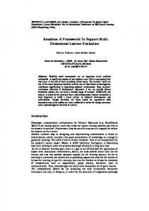
3.4. Primarily graphical approach Modeling frameworks may be dependent or independent of a graphical notation. For example, the IDEF0 modeling method specifies a formal notation in which functions are represented as boxes. The approach defines the boundary with which an arrow intersects to signify a certain relationship: edges entering the left boundary are inputs; edges leaving the right are outputs; and inputs to the top and bottom boundaries represent controls and mechanisms respectively. Many graphical approaches provide less specific notation. For example, PERT charts are represented in digraph form without attaching meaning to node boundaries. Other modeling frameworks are defined in terms of their elements and relations without stipulating a graphical notation. Examples include O’Donovan’s Extended Signposting [4]. Although such approaches may provide means to manipulate models, they aim to separate the concerns of representation and user interaction. Any modeling approach can be strongly influenced by the interfaces provided for its use. In the case of models which must bring together previously undocumented knowledge about the design process, an appropriate user interface is considered critical to support negotiation of shared understanding during the modeling process. An intuitive visual format allows domain experts who are unfamiliar with the nuances of the approach to become involved in modeling. To ensure an effective user interface the ASM framework and implementing software tools have thus been developed in parallel; each feature was considered both in terms of the aspects of the design process it was intended to represent and its effective implementation in the modeling interface. Although several visualizations are provided by the tool described in section 4, the ASM should thus be considered a primarily graphical approach. Figure 1 depicts the primary notation of a simple ASM model. The figure illustrates the color-coded depiction of simple tasks (‘T1.2’, ‘T2.1’), an iteration construct (‘T1.7’), a data interaction (‘P1.3’), flow interactions (‘P1.1’, ‘P1.4’ etc), and a container task and its subprocess (‘T1.5’ and ‘Pr. 2’ respectively – see section 3.5.2). The durations of tasks and the simulated durations of processes are also shown to provide a simplified interface to simulation functionality. Element properties which are used in more sophisticated ASM models (including parameter scope, execution conditions and
4
Copyright © 2006 by ASME
resource requirements – sections 3.5.3, 3.6.1 & 3.6.3) are incorporated as icons above the associated task or parameter.
not constrained to a tree structure. The task hierarchy in an ASM model is typically lattice-structured as shown in figure 2.
P1.1 2d 3d 6d
Pr. 1 1d
T1.2
P1.3
T1.5 1h 8h 1d
Pr. 2 1h 1d
P1.4
Figure 2: ASM models are typically lattice structured due to re-use of process elements
T2.1
Iterate again
3.5.2. Model composition 1d
T1.7
P1.6
P1.8
Figure 1: The primary notation of an ASM model 3.5. Hierarchical structuring The ASM supports hierarchical structuring of tasks and parameters. The hierarchical elements have been developed in response to requirements arising during application of the approach, particularly to support manipulation and presentation of large models. They form the major driver of complexity in the modeling framework and its user interfaces. As with other aspects of the framework, complex hierarchical structures may be used as required and are not necessary to construct simple models. Multiple task and parameter hierarchies are available and can inter-mesh to allow development of more sophisticated structures than many other approaches. These features will be described in subsequent sections.
3.5.1. Primary task hierarchies Task hierarchies in an ASM model serve several purposes. Firstly, the explicit contextual information supports navigation and has been found essential in all but the smallest models; ‘opening’ and ‘closing’ tasks to focus on their detail enables effective visualization and manipulation without overwhelming the user. Furthermore, hierarchical task description improves accuracy of knowledge elicitation and representation. To illustrate, consider two similar activities carried out at different times to achieve different goals. The task elements representing them are typically described using similar terminology although the underlying activities and information requirements may be very different. In this situation it is often unclear from textual descriptions alone what each task is intended to represent. This leads to difficulty in eliciting knowledge such as information requirements or expected duration, particularly where the information is subject to interpretation or is distributed amongst several process participants. In practice, hierarchies have been found to carry more precise contextual information than purely textual descriptions, providing an intuitive representation which allows similar elements to be easily distinguished in large models. Secondly, task hierarchies allow specification of process elements for re-use in different contexts throughout a model. For example, a process entitled ‘liaise with suppliers’ might represent a detailed, prescriptive procedure involving the logistics department. Since many design teams may liaise with suppliers and must follow similar steps, it may be appropriate to define a single process element which can be used to represent each liaison in its local context. An implication of re-using process elements is that task hierarchies are
In contrast to most hierarchical modeling frameworks ASM processes are not decompositions of a higher-level task; rather, each process is composed of other processes. As a model is constructed its processes accumulate in a process library from where they may be referenced multiple times if required. An ASM process element is defined as an encapsulation of a set of tasks and parameters, together with input and output interactions exposed from within the process. In figure 1, ‘P1.1’ is exposed as an input interaction and ‘P1.8’ as an output interaction from the process ‘Pr. 1’. In the ASM processes differ from tasks in that, dependent on the structure within, work may begin before all input interactions occur and output interactions may occur before work is completed. Concurrent activities which exchange information during execution are thus represented as an aggregate of subordinate tasks. Each task in a process defines its own parametric context, in terms of its input and output interactions which refer to parameters within the process. Tasks in a process interact directly because their contexts overlap by reference to the same parameters. Unlike a task, a process in the ASM has no ‘parent’. Its context cannot therefore be defined in terms of parameters with which other tasks may directly interact. Each time a process from the library is inserted into a parent process, appropriate parametric context must be provided by wrapping it in a container task. This is an element in the parent process that maps the exposed interactions of the wrapped process to interactions defined in the parent process. A process thus provides detail for one or more container tasks and each container task provides one context for its wrapped process. Figure 3 illustrates use of a container task to provide parametric context for a process, showing the mapping detail which is hidden in the primary view. In this example, the ‘P2.6’ ellipse depicts an output interaction exposed from ‘Pr. 2’. The container task maps this to an interaction with ‘P1.6’ defined in ‘Pr. 1’. P1.1 2d 3d 6d
Pr. 1
1h 1d
1d
T1.2
P1.3
T2.1
T1.5 1h 8h 1d
Pr. 2 1h 1d
P1.4
T2.1
P2.6
Iterate again 1d
T1.7
P1.6
P1.6 P1.8
Figure 3: Container tasks and mappings in the ASM
5
Copyright © 2006 by ASME
Although this scheme may appear complex, the details of container tasks and mappings are handled almost transparently by the software implementation. The benefit of the approach is that library processes remain independent of the contexts in which they are used. Once interfaces are defined processes may thus be modified directly from the library and all instances will be updated accordingly. This facilitates incremental development and maintenance of a knowledge base from which many models may draw.
3.5.3. Primary parameter hierarchies In many design processes the hierarchy of activities can be seen to parallel organizational structures. For example, stress analysis is carried out by mechanical engineers and its detail may not be well understood by the aerodynamics group. This structure is reflected in the visibility of certain design information; intermediate data files generated during stress analysis have little relevance outside this context. Other information such as component definition files or requirements documents must be shared among several teams to coordinate their work. A representation of design information should therefore reflect the hierarchy of activities while permitting deviation from this structure. Furthermore, it is often useful to model relationships between items of information, for example to specify that ‘engine requirements’ incorporates ‘fan requirements’. The ASM framework allows parameters to be structured into trees to allow description of these part-of relationships and to support modeling of large numbers of parameters at different levels of detail. In the example above, ‘fan requirements’ might be modeled as a subparameter of ‘engine requirements’. In this case, a task which interacts with ‘engine requirements’ is considered to also interact with ‘fan requirements’. The parameter hierarchy is defined as secondary to the task hierarchy of previous sections such that each process encapsulates one or more tasks and a number of hierarchical parameters. To allow parameters in distinct processes to represent the same information, their scope may be broadened by exporting them from a super-process into its sub-processes. In figure 1, the parameter ‘P1.6’ is exported from the process ‘Pr. 1’ into the process ‘Pr. 2’. This is indicated by an icon above the parameter node. In this case the parameter scope is modified automatically as part of the mapping operation, since any parameter which represents information transfer across an interface must by definition be visible to both processes.
3.5.4. Secondary task and parameter hierarchies In practice models quickly become large enough to present difficulties in navigation and manipulation. In these cases it is necessary to work with subsets of a model to reduce the computational requirements of manipulation and prevent ‘information overload’ for the user. Although the hierarchies described above support this to some degree, it is often beneficial to define perspectives which cut across the primary structure of a model. For example, to examine the role which data files play in the process it is useful to 'hide' parameters representing other types of information. Similarly, when developing a model through feedback to several process participants it can be advantageous to focus on individuals' tasks and the contexts in which they take place. The primary hierarchies described in previous sections affect both static and dynamic behavior of the model and consequently the way in which it represents its target system. Perspectives should be superimposed on this primary structure so they can be developed and modified without affecting these aspects of the model. To serve this need the ASM allows definition of secondary hierarchies for both tasks and parameters in terms of multiple userdefined classification schemes and classification categories. Any task or parameter may be placed in a number of schemes and categories, enabling mark-up of these elements with additional information. The software implementation described in section 4 can process these
structures to develop perspectives of the process model. Network views, for example, can be filtered to provide simplified visualizations whose layout is coupled to the primary view.
3.6. Model execution and simulation analysis A key motivation for adopting a process modeling framework is that such approaches offer benefits beyond informal graphical models. In particular, a model may be analyzed to determine ways in which the underlying process might be improved. The ASM supports step-wise execution of process models. An executable model may be used to guide or drive a design process directly. It may also be simulated to explore aspects of process behavior such as estimated duration, cost and task timings. The following sections describe model elements which determine execution and simulation behavior.
3.6.1. Task selection The process execution algorithm is similar to the Petri net approach used by McMahon and Xianyi [5] and is described by Wynn et al. [3]. The algorithm assumes that process state is sequentially modified by discrete events (task starts, task completes, etc). In this context, process state consists of the current availabilities of input information for each task in the model (unavailable, available, or recently updated for each parameter-qualifier combination), current resource availabilities and current values of process variables (see below). This algorithm has been developed to allow execution of models structured intuitively as flowcharts; tasks are attempted in the order implied by flow interactions in the model. Depending on the structure of interactions in the model, tasks may be available to begin under different circumstances. For example, most design activities must be re-worked following the update of any input information, whereas activities involving integration of parallel work streams cannot be attempted until all streams are complete and all input information has been updated. The approach thus allows specification of the logical conditions under which each task is available to begin. In the above example, the former type of task should be specified as requiring updates to any input parameters to begin, whereas the latter integration-type tasks require updates to all input parameters. In addition to the task execution conditions described above and the interaction structure of a model, the route taken during process execution is influenced by the scenario selection algorithm specified for tasks with more than one output scenario. Scenario selection can be modeled as a stochastic process by specifying the probability of each scenario occurring. Alternatively, it may be specified in greater detail using process variables and functions.
3.6.2. Process variables and functions Process variables can be defined to represent numeric values which may change during a process. Examples of such values include metrics such as ‘cost’ or ‘confidence’ and ‘control variables’ which are used to determine execution behavior. Variable values are sequentially modified by functions which may be defined using an intuitive syntax and attached to the output scenarios of tasks in a model. When a task is completed during execution, any functions are evaluated to determine the new value of each process variable. Expressing task durations and scenario selection decisions as functions of process variables allows simulation models to be developed which exhibit dynamic behavior more realistic than purely stochastic models. To illustrate, consider that process decisions and other unpredictable activity characteristics are not always entirely random, but are contingent upon events which occurred previously. For example, the time required to reassemble an engine module after servicing is dependent upon the degree to which it was disassembled; as a design is refined more time is devoted to detailed analysis with
6
Copyright © 2006 by ASME
each iteration; and the iterative refinement of a component design often continues until some parallel activity is completed. Process variables and functions provide a flexible means to incorporate such contingencies, which can strongly influence the behavior of a simulation model. This allows users with limited programming knowledge to develop graphical models exhibiting complex dynamic behavior.
3.6.3. Resource constraints The ASM framework allows specification of resource requirements for each task. Each resource requirement indicates a number of units of a resource which the task requires to execute. Resource elements consist of an availability profile, describing how many units are available between given dates, and a calendar, indicating the hours and days for which the resource is available. The simulation algorithm assumes that a task cannot begin until the specified units of all required resources are available in the pool. These resources are removed from the pool during execution of the task. Subject to other aspects of model configuration, resource constraints may thus affect simulation behavior. For example, where several tasks compete for the same resource it is assumed that one task is selected at random and executed at full capacity. Other competing tasks cannot then be attempted until the first is complete.
4. P3 SOFTWARE IMPLEMENTATION The ‘P3’ software provides an environment for manipulating and simulating ASM models. The tool is available for download from http://www-edc.eng.cam.ac.uk/p3/. Due to space constraints a full description of P3 is not possible here. A key feature is the provision of several visualization approaches, all of which allow direct manipulation of model data. Network displays use an assisted layout algorithm to reduce the manual overhead of manipulating hierarchical networks while allowing users to influence node positioning. This enables
development of larger models than are feasible using many existing tools. For example, the largest model described in section 5 requires 1271 network nodes to display using the notation of figure 1. Other views include task DSMs derived from the model connectivity structure and tasks tabulated against the resources they require. These tabulations provide a concise overview of dependencies which are not explicit in the primary network display. In addition to implementing the ASM approach, P3 aims to support future research by allowing rapid prototyping of other linkage-based modeling frameworks. A graphical configuration tool thus allows extension or re-definition of the modeling framework by declaring new element classes, properties, relations and perspectives. To illustrate, an element class Requirement could be defined with properties such as Description and Importance. An appropriate relation added to the ASM Task element would then allow representation of the requirements which tasks address. Defining a tabulation perspective would provide a connectivity matrix allowing linkages between tasks and requirements to be manipulated. A plug-in architecture and JavaTM Application Programming Interface (API) allow development of more sophisticated extensions. For example, one such package defines the scriptlet element, a list of which may be associated with each task in a model. Scriptlets are written in JavaTM and may be developed and compiled without leaving the modeling environment. When a task is attempted during process execution its scriptlets are executed. Scriptlets have full system access; they may, for example, be used to generate dialogs in P3 or execute codes external to the modeling environment. They may also be used to generate input files for such programs and parse any output data, thereby synchronizing aspects of the design definition with the process variables used to control execution routes. This allows an ASM model to directly drive computational design processes, at each step using current design data to inform selection of the next task.
Figure 4: Screenshots from the P3 software illustrating various process visualizations. Simulation of the model allows selection of a schedule which captures risk associated with uncertainties in task outcome and duration. Schedules give feedback indicating the feasibility of completing the modeled process in the allotted time.
7
Copyright © 2006 by ASME
5. CASE STUDIES The approach has been applied in four case studies, each undertaken by a different individual over a period of several months (table 1). Each study involved development of an ASM model in close collaboration with a large UK aerospace company. In following paragraphs two studies are described to illustrate application of the approach, prior to a more general discussion highlighting key findings from the research.
Table 1: ASM models developed during case studies with a large UK aerospace company Model
Tasks / interactions
Primary tool user
1. Fan blisk 2. Fan blisk 3. Turbine 4. Turbofan
94 / 307 98 / 304 314 / 1557 392 / 1236
First author Blisk design manager Cooling designer University researcher
Model
Elicitation methods
Purpose
1. Fan blisk 2. Fan blisk 3. Turbine 4. Turbofan
8 month onsite case study Experience Experience / interviews Interviews / documentation
Scheduling [3] Visualization What-if? [22] Visualization
The two studies described in following paragraphs concern the fan ‘blisk’ for a military turbofan. The blisk is a complex, highperformance component whose design is a team activity involving a number of engineers and support personnel. Its design process may be described to a large extent in terms of particular design and analysis tools driven by the data files which carry the component definition. Within this established working structure the design is modified according to an emerging understanding of its requirements and behavior. In common with many engineering design processes, blisk design is thus characterized by a large number of refinement iterations during which specialist designers must co-ordinate their efforts to negotiate complex technical trade-offs. In practice this is achieved through a combination of informal communication and regular co-ordination meetings to identify current design goals, which can change to reflect issues in the emerging solution. Study 1 was initiated at the request of the program manager for a new engine project, who was considered at that time to represent the primary end-user of the approach. In an early phase of the project the component's design-make plan had scheduled manufacturing processes in great depth – by contrast, tasks in the design phase were described in much less detail. Project management personnel believed that unpacking these ‘black box’ design schedules into a number of smaller tasks could improve monitoring of progress on the design. This would lead to quicker identification of potential schedule slippages and ensure timely remedial actions were taken. Initial observations and interviews determined that existing Gantt-based scheduling packages did not adequately represent design process plans. Schedules constructed in these tools were timeconsuming to maintain and quickly became outdated, typically due to unexpected tasks or iterations. To address this shortcoming a new planning approach was developed. The approach is based on the assumption that, although the schedule is subject to change through the course of a project, it is based on a more stable plan which may be modeled using the ASM. Plans are thus modeled to capture the tasks to be scheduled, information flows and key design iterations. Many plans may be expressed as a parameterization of this model, in terms of planned task durations and numbers of expected refinement iterations. Furthermore, estimating the likelihoods of task failure or duration over-run also captures the risk associated with these events. To generate or re-generate a schedule, the following activities are undertaken: 1) modify the model to reflect any changes in the plan; 2)
simulate the model to explore the set of possible schedules; and 3) select a single instance from this set that is considered an adequate trade-off between milestone constraints, schedule risk and the time desired for future design activities. The selected instance may be presented as a Gantt chart to form the new schedule [3]. During this study the first author acted as facilitator of the modeling process over a six month period. Modeling was conducted in parallel with early development of the ASM framework and a prototype software tool. The research included many discussions with both management and technical personnel, together with study of existing documentation and a small number of group workshops. The model was structured such that simulation would produce a Gantt chart which revealed a ‘staggered’ activity breakdown against which project progress could be monitored. Furthermore, it was important to capture the design process at a level of detail appropriate to the schedules which would be generated. A process library of generic ‘building blocks’ was constructed, many of which incorporated iteration cycles modeled using iteration construct tasks. These independent building blocks may be parameterized and connected in linear fashion to represent a particular plan of work. An example of such a planning network and a schedule generated by simulation is shown in figure 4 (Note that data have been modified to protect confidentiality). A pilot study is planned in which the approach will be evaluated by application to a ‘live’ project in the same company. In study 2, the P3 software was used by a cross-functional manager responsible for timely delivery of rotative fan components for the same project. The objective of the study was to develop a comprehensive description of the blisk design process with the aim of exploring the impact of each task on process duration. A detailed model capturing the design tasks and parameters was developed, together with a credible representation of the process dynamics. The model follows the approach of McMahon and Xianyi in describing the design process as concurrent work streams that are integrated in a process of iterative refinement [5]. Figure 5 illustrates one process from this model, omitting data interactions to clarify the execution structure. In this process, initial data preparation tasks (A14) lead to four concurrent work streams, represented as processes that are independent during execution (B1-4). Upon completion of these streams a compound task representing a co-ordination meeting is undertaken (D). This task has four output scenarios representing a decision taken during the meeting regarding the focus of design and analysis for the next iteration, and one to indicate process completion. The first four scenarios lead to tasks which modify the design definition to incorporate recent advances (E1-4). The selected task also updates process variables to reflect the outcome of the decision. These variables determine whether time-consuming detailing tasks (C2-4) are attempted in the next iteration. E1-4
In
A1 A2
A3
A4
B3 B2
B4
B1 C4
C2 C3
Out D
Figure 5: Overview of a process from blisk model 2
8
Copyright © 2006 by ASME
6. DISCUSSION 6.1. Knowledge elicitation and the modeling activity No model is fully representative of its target system and this is not necessary for a model to be useful. This is underlined when modeling the design process; each of the models described above has changed substantially as its structure and purpose has been explored during development. In each case, the model’s construction followed a highly iterative process of critique and refinement, with the modeler’s understanding of the process developing in parallel with their model. Although each case had a well-defined process improvement goal to guide initial modeling, additional uses for the models suggested themselves during construction. This led to refinements of the structure, nomenclature and perceived representativeness of the models. Ultimately each model was considered to serve several of the purposes discussed in section 2.1. In each case this included a detailed process description and capture of dynamic process behavior. It was further observed that modeling did not proceed through incremental improvements alone. In all four case studies, leaps in understanding led to substantial restructuring and on several occasions to an entirely new model. This iterative process may be as characteristic of process modeling as it is of designing, and highlights the importance of effective user interfaces to facilitate model manipulation. Development of the models has been a lengthy and extremely knowledge intensive process. However, in all cases eliciting process information formed only one aspect of the modeling activity; a great of effort was also expended by each user in reflecting on how the model should be structured to most effectively represent the knowledge they had gained. Users believed they had developed a much deeper understanding of the design process and its behavior as a result of this activity.
6.2. Support for modeling In each study, the approach has enabled development of models exhibiting significantly more detail than was shown in previous process descriptions. Furthermore, users have indicated a desire to continue adding detail in terms of both breadth and depth. This observation has driven the research towards developing a framework and software tool which can represent very large models. Such scalability is considered a necessary foundation for modeling and analysis techniques which can be deployed in industry. The software package described in section 4 allows the construction of models of varying sophistication, ranging from descriptive flowcharts through to simulation models which account for contingent decisions. Given the relatively large number of elements available for modeling and the flexibility of the framework, it is inevitable that difficulties are encountered when users first apply the approach. In the studies, each subject encountered very similar issues when beginning to use the modeling software. These related both to the modeling interface and to the appropriate use of the model elements. Explaining features of the framework as solutions to these issues as they are encountered has proved an effective method to communicate their use; each user developed models of increasing sophistication as they became more familiar with the system. A modeling framework such as the ASM should be accompanied by a method for process improvement to maximize its utility. The approach presented in this paper allows construction of models for a range of purposes; however, each case study had specific goals which the modeling software was applied to address. Future research will address the need for a more systematic methodology to guide novice users in achieving full benefit from the approach. Due to the flexibility of the framework, this methodology
is likely to take the form of a list of process improvement activities together with guidelines for use of the software in each case.
6.3. Challenges in building re-useable models The flexibility of any modeling framework to represent different processes may be considered from various perspectives. From a framework perspective, many models may be constructed using a particular approach, each of which may represent different processes for different purposes. A particular model may also be flexible on an interpretation level – in that models mean different things to different people – and on the level of the target system. The latter refers to the ability of a model to be instance-independent. For example, the process model discussed above is both a specific and generic representation. It provides a description of a specific instance of the blisk design process, but also has potential to represent aspects of future or similar processes. This flexibility raises the possibility of developing a process library which can represent not only similar aspects within one model but from which many models may be composed. Austin et al. describe such a library of building blocks for the construction industry, stating that a process model constructed from their library can account for 90% of the activities in a typical construction project [21]. If this success could be repeated across other sectors or even within companies in these sectors, it could dramatically reduce the effort required to construct process models and thus facilitate the uptake of modeling approaches within industry. However, our studies in the aerospace sector indicate that while high level task descriptions might change little from product to product, details can vary significantly. In terms of products, some components or systems are typically adapted and carried across, or modified on a parametric level, while others require high-risk innovative solutions. In terms of processes, case studies 1-3 in table 1 address very specialized technical design problems, each of which is carried out using specific tools, analyzes and solution principles. As such, sub-processes are not recognizably similar across the models. Although in each case designers have indicated that their particular processes remain similar across product generations, it is not clear whether a generic library would provide an effective starting point for developing models in these studies. Two key challenges are evident in developing libraries of reuseable ASM processes. Firstly, effective re-use of a process within and across models hinges on achieving an appropriate form and level of abstraction. In particular, interface definitions must be carefully considered to ensure that the exposed parameters are appropriate to the process and to all contexts in which it is used. For example, the same process cannot represent activities at the ‘assess customer needs’ level and the ‘parametric optimization’ level, since the abstraction of interface parameters must be significantly different in each case. The ability to highlight such interface mismatches is considered a key benefit of the ASM since it encourages development of well-structured and self-consistent models. However, the need for interface consistency also limits the possibilities for process re-use, since processes are inevitably tailored to fit their original contexts. In practice, it has been found that several ‘iterations’ of an interface definition are necessary before a process can be effectively re-used. The second challenge lies in the implicit assumption that all aspects of a process’ definition should be encapsulated by its boundaries and interfaces. In practice, dynamic behavior often cuts across the primary structure of a model, thereby coupling processes which are otherwise independent. This is highlighted in the process shown in figure 5. In this example, co-dependencies on control variables couple tasks C2-C4 to tasks E1-E4 in the parent process. Thus, although careful definition of interface parameters allows reuse of process elements, the behavior of tasks within each process must also be considered when constructing a simulation model.
9
Copyright © 2006 by ASME
7. CONCLUSIONS This paper has described the features and application of a process modeling framework which may be used to model design processes at varying levels of abstraction. Models constructed in the framework can range from descriptive flowcharts used to capture expert knowledge through to executable models, in which parameters represent data files that are processed by tasks which drive execution of design codes. The approach considers design processes to be composed of discrete tasks which are coupled by shared interactions with input and output parameters. A distinction is made between interactions that drive task selection and those which inform task execution. This distinction allows detailed specification of process behavior alongside a rich description of information dependencies between tasks. An intuitive graphical notation and multiple hierarchical structures facilitate construction of large models. Where necessary, the dynamic behavior of these models can be precisely specified using process variables to control task durations and outcomes. Models can be executed to guide the design process or simulated to explore process behavior. The framework is implemented in the ‘P3’ modeling software which has been developed in close collaboration with industry. The implementation is designed to facilitate construction and manipulation of large models, aiming to provide benefit over generalpurpose diagramming packages even when simulation or execution features are not used. A great deal of effort has been expended to ensure the complex definition of the modeling framework supports construction of useful models without obstructing the user interface. In addition to the simulation functionality, a scripting facility allows executing process models to interact with resources external to the modeling environment. At the time of writing, the software is being applied by several users in industry and academia. Although a formal evaluation has not yet been undertaken, acceptance of the modeling software by these users represents a preliminary validation of the research.
ACKNOWLEDGEMENTS This research is funded by the EPSRC. The authors wish to thank Chris Powell and Udo Pulm for their contributions during case studies. Special acknowledgement is made to Seena Nair for her programming work and to Chris Bell for many challenging discussions.
REFERENCES [1] Bracewell, R. H., Shea, K., Langdon, P. M., Blessing, L.T.M. and Clarkson, P.J., “A methodology for computational design tool research”, ICED’01, Glasgow. [2] Eckert, C. M. and Clarkson, P. J., 2003, “The Reality of Design Process Planning”, ICED’03 Stockholm. [3] Wynn, D. C., Clarkson, P. J. and Eckert, C. M., 2005, “A modelbased approach to improve planning practice in collaborative aerospace design”, ASME Design Engineering Technical Conferences, Long Beach, California, USA. [4] O’Donovan, B.D.O., Eckert, C.M. and Clarkson, P.J., 2004, “Simulating design processes to assist design process planning”, ASME Design Engineering Technical Conferences, Salt Lake City, Utah, USA. [5] McMahon, C. A. and Xianyi, M., 1996, “A network approach to parametric design integration”, Research in Engineering Design, 8(1), pp. 14-31. [6] Jarrett, J.P., Dawes, W.N. and Clarkson, P.J., 2004, “An approach to integrated multi-disciplinary turbomachinery design”, ASME International Gas Turbine Institute TURBO EXPO 2004, Austria Center, Vienna.
[7] NIST, 1993, “Integration definition for function modeling (IDEF0)”, Federal Information Processing Standards (FIPS) Publication 183, National Institute of Standards and Technology, Gaithersburg, MD, USA. [8] Mayer, R., Menzer, C., Painter, M., deWitte, P., Blinn, T., Perakath, B., 1995, “IDEF3 process description capture method report”, Knowledge Based Systems Incorporated, Texas, USA. [9] Kusiak, A., Larson, N. T. and Wang, J., 1994, “Reengineering of design and manufacturing processes” Computers and Industrial Engineering, 26, pp. 521-536. [10] Steward, D.V., 1981, “The design structure matrix: A method for managing the design of complex systems”, IEEE Transactions on Engineering Management, EM-28(3), pp.71-74. [11] Eppinger, S., Whitney, D., Smith, R. and Gebala, D., 1994, “A model-based method for organizing tasks in product development”, Research in Engineering Design, 6, pp. 1-13. [12] Cho, S. and Eppinger, S.D., 2001, “Product development process modeling using advanced simulation”, ASME Design Engineering Technical Conferences, Pittsburgh, Pennsylvania, USA. [13] Browning, T.R., 2001, “Applying the design structure matrix to system decomposition and integration problems: a review and new directions.” IEEE Transactions on Engineering Management, 48(3), pp. 292-306. [14] PMI Standards Committee, 2000, A project management body of knowledge (PMBOK). Project Management Institute. [15] Moore, L.J. and Taylor, B. W., 1977, “Multiteam, multiproject research and development planning with GERT”, Management Science, 24(4), pp. 401-410. [16] Dou, W. C. and Cai, S. J., 2002, “Hybrid system for functional analysis on different stages of production system lifecycle”. CE2002, Cranfield, UK. [17] Clarkson, P. J. and Hamilton, J. R., 2000, “Signposting: a parameter-driven task-based model of the design process”, Research in Engineering Design, 12(1), pp. 18-38. [18] Lawson, B., 1980, How designers think, The Architectural Press Ltd., London. [19] Scheer, A-W., 2000, ARIS – Business process frameworks, Springer, New York. [20] Freisleben, D. and Vajna, S., 2002, “Dynamic process navigation: modeling, improving and review of engineering processes”, ASME Design Engineering Technical Conferences, Montreal, Canada. [21] Austin, S., Baldwin, A. Li, B. and Waskett, P., 2000, “Analytical design planning technique (ADePT): a dependency structure matrix tool to schedule the building design process”, Construction Management and Economics, 18(2), pp. 173-172. [22] Bell, C.P., Dawes, W.N., Jarrett, J.P. and Clarkson, P.J., 2005, “Improving the conceptual design of turbine rotor blade cooling systems”, ICED’05, Melbourne, Australia.
10
Copyright © 2006 by ASME