hardware connected to a PC. ... dedicated hardware, designed specifically for an applica- tion e.g. .... Fault detection problems â Network monitoring systems â.
Proceeding of the First National Conference on Security, Computing, & Communications (1st NC-SCC 2008), KUST, NWFP, Pakistan May 23-25, 2008
Architecture of reconfigurable artificial neural network Co-processor Kamran Rauf, Muhammad Usman and Abdul Bais Department of Computer Systems Engineering NWFP University of Engineering and Technology Peshawar, Pakistan
communication between the co-processor’s top module and sub-processors and also with in the sub-processors. There is also a network structure designed for the communication of layers with in a sub-processor. The co-processor reported in [5, 6] and the proposed architecture depend on the backpropagation network. The rest of the paper is organized as follow: The architec- ture of the backpropagation network is described in Section 2. This is followed by a detailed presentation of the proposed ar- chitecture of the co-processor based on backpropagation with online learning in Section 3. Finally, the paper is concluded in Section 4.
Abstract — In this paper we propose the architecture of a neural co-processor for on-board learning. The co-processor is based on backprop- agation network and acts as a dedicated hardware connected to a PC. It consists of several sub-modules i.e. sub-processors rep- resenting a column of the backpropagation neural network. The architecture allows the co-processor to form any structure de- pending on the specific application. We have built a communi- cation network for the sub-modules to communicate with each other and within each sub-module; there is also a communica- tion network for the layers to communicate with each other. The operations of each sub-processor are independent from other sub-processors i.e. a neuron calculates its output as soon as all inputs are available.
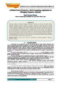
II. BACKPROPAGATION NETWORK ARCHITECTURE Backpropagation network shown in Fig. 1 is a multilayered neu- ral network with n sub-processors (neurons). A sub-processor has an input layer (X), an output layer (Y) and hidden layer(s) (H) [7]. X 0, X 1, ..., X n represent the input layers, H 00, H 01,..., H 0n show first hidden layers, H 10, H 11, ..., H 1n show the second hidden layers, H m0, H m1, ..., H mn show mth hid- den layers and Y 0, Y 1, ..., Y n represent the output layers of n sub-processors as shown in Fig. 1. Each column in Fig. 1 repre- sents a sub-processor i.e. a neuron which is connected to other neurons.
I. INTRODUCTION Large training time in neural network is the fundamental ob- stacle in real time applications. A computer based neural net- work program can’t solve the timing problem, as the essence of the neural net is the parallelism which a single processor can not give. There are several commercial softwares that are using neural network algorithms to solve different problems. These softwares can not provide mobility and good training time [1]. There are also a few commercialized chips available for the neu- ral network applications but these chips do not have the capabili- ties of on-chip learning because these chips do not train the neu- ral network but take the weights that computer has calculated for it [1]. One of the vendors of these chips is Intel, with its 80170 ETANN (Electronically Trainable Artificial Neural Net- work) chip and Neural Semiconductor, with its DNNA (Digital Neural Architecture) chip [1]. There is a demand for a dedicated hardware that can be trained for different applications. Some attempts have been made for the dedicated hardware, designed specifically for an applica- tion e.g. [2], [3] etc. The main thing in the hardware implemen- tation is the communication structure. The more the communi- cation structure is efficient, the higher is the performance of the hardware. This constitutes the architecture of the co-processor which will act as a dedicated neural hardware. One of the fa- mous dedicated hardware co-processor based on self organizing map neural networks is KOKOS [4]. The first on-board learning based on backpropagation network KOBOLD is presented by M.Bogdan, H.Speckmann and W.Rosenstiel [5, 6]. In [5, 6] architecture, they implement a communication struc- ture on the basis of bus topology. There is a global bus, to which all sub-processors are connected and a local bus which is con- necting the sub-processors in a ring like structure. The prob- lem in this communication structure is that while propagating error difference to other relevant sub-processors, only one sub- processor is allowed to do so and all other wait for their turn. So there is a significant delay for the sub-processors. Also com- municating via local bus, the sub-processor sends its data on the bus and the neighbor collects it, which observe the packet for its relevancy. If the packet is for that sub-processor, it will save it in its local memory and if not, it will forward it to its neighbor. This method of communicating weights produces a significant delay. For faster communication, the delays are to be reduced to their possible level. In proposed architecture there is a spe- cial switching center used for the
Fig. 1 Architecture of Backpropagation network
There are two modes of operations in training of backpropa- gation network, forward propagation and backpropagation [7]. In forward propagation, the network input patterns are presented to input layer which calculate its products and convey it to the above hidden layer and associated sub-processors’ hidden layer. Then each hidden layer calculates its net input and output which is then conveyed to the layer above of the current sub-processor and other connected sub-processors. Similarly the process is continued in other
41
Proceeding of the First National Conference on Security, Computing, & Communications (1st NC-SCC 2008), KUST, NWFP, Pakistan May 23-25, 2008
its required data, it will calculate its output and convey it to the relevant layer and sub-processor (if needed). The proposed architecture of the co-processor is described in the followed Section 3.2.
sub-processors as well until final layer i.e. output layer calculate its output [7]. In backpropagation mode each sub-processor’s output layer then computes the error difference and if it’s greater than a spec- ified tolerance level than all layers below the output layer up- dates their weights. Similarly the error is also conveyed to the connected sub-processors, so that they can also compute their new weights [7]. The whole training is followed in this trend.
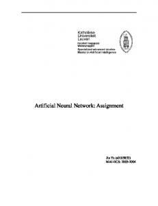
III. PROPOSED ARCHITECTURE In this section, we will describe the co-processor architecture. The section is broken in to the following sub-sections: first we will describe the hierarchy of modules involved in the imple- mentation of co-processor in Section 3.1, then the proposed co- processor architecture in Section 3.2 and finally the sub-processor architecture in Section 3.3. A. Hierarchy of Modules The code implementation of the co-processor comprises six ma- jor modules. The hierarchy of the modules is given in Fig. 2. In Fig. 2, the CoProcessorTopModule is the top module which is receiving configuration instruction and pattern-target pairs from external environment. To configure the co-processor, user give instructions through PC interface and these instructions are con- veyed to the co-processor’s top module which configures the co- processor accordingly.
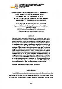
Fig. 3 Co-Processor Architecture B. Co-Processor Architecture Architecture of the co-processor shown in Fig. 3 is very simi- lar to a star topology network. There is a special switch named MainSwitchingCenter. In Fig. 3 the top module which provides the external environment interface is CoProcessorTopModule and the adjacent blocks represents the sub-processors which are the basic processing elements of the co-processor. There are sixteen sub-processors in the proposed architec- ture. The number of the sub-processors can be increased to two hundred and fifty six. They can also be extended to more than two hundred and fifty six by increasing word size but by increas- ing the number of sub-processors, the complexity of the network will also increase. Also we need the same number of pins in the co-processor as that of sub-processors, so that in applications all sub-processors can be given patterns simultaneously which is not a feasible solution. Applications that are having sixteen dependent parameters can be dealt with it. Within each sub- processor there are ten layers working autonomously. The ar- chitecture of the sub-coprocessor is described in the following sub section.
Fig. 2 Hierarchy of modules
The MainSwitchingCenter is the main module for communi- cation. The whole communication of the co-processor depends n this special switching center. The MainSwitchingCenter is like a switch in a star topology network but it is specially de- signed to work for the parallel structure of the co-processor and present less delay to the data. The MainSwitchingCenter is de- signed in a way that it can receive data from its all ports and can send data on all its ports simultaneously which makes the co- processor faster. Each sub-processor is assigned an address in order to identify the sub-processors. Each sub-processor starts its calculations for itself and then it calculates products and other results for its forward neighbor which ensures that no two sub- processors are sending data to same sub-processor and in this way the collision is avoided. This method also increases the speed of communication. For further optimization in speed, the co-processor implementation is pipelined. SubProcessor is the basic processing device in the co-processor.. It is like neuron in biological nervous system. Each SubProces- sor has three different kinds of layers i.e. InputLayer, Hidden- Layer and OutputLayer as show in Fig. 2. These layers work simultaneously and the whole process is carried in a way that as soon as a layer has
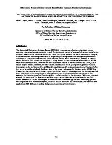
C. Sub-Processor Architecture The special architecture of sub-processor shown in Fig. 4 resembles to that of a bus topology network. The SubProcessor is the top module for this portion of co-processor. It receives the configuration instructions, patterns and targets sent by co-processor and products and error differences sent by other sub-processors from MainSwitchingCenter and accordingly it maneuver its layers.
42
Proceeding of the First National Conference on Security, Computing, & Communications (1st NC-SCC 2008), KUST, NWFP, Pakistan May 23-25, 2008
IV. CONCLUSION We presented a new architecture for digital neural co-processor for online learning backpropagation. The architecture of the co-processor leads to better performance. The communication network leads to asynchronous communication between subprocessors and also with co-processor’s top module. Further work is in progress on the co-processor. The major steps that are left include the implementation of PC interface for configuration and implementation of other backpropagation algorithms for further optimization. This hardware implementation can lead to a powerful neuro-computer that can be used in a wide range of applications such as: ” Optical character recognition ” Image and Data compression ” Load forecasting problems in power system area ” Control problems ” Non linear simulation ” Biomedical applications ” Fault detection problems ” Network monitoring systems ” Communication etc
REFERENCES [1] Ingrid F. Russell, “Neural networks,” 2007, [Online: www.hartford.edu, accessed 12-09-2007]. [2] Johannes Schemmel, Karlheinz Meier, and Eilif Mueller, “A new vlsi model of neural microcircuits including spike time dependent plasticity,” in Proceedings IEEE International Joint Conference on Neural Networks, Kirchhoff Inst. for Phys., Heidelberg Univ., Germany;, 2004, vol. 3, pp. 1711– 1716. [3]
Michael Freeman, Michael Weeks, and Jim Austin, “Aicp: Aura intelligent co-processor for binary neural networks,” in IP-SOC 2004 IP Based SOC Design Forum and Exhibi-tion.
[4]
H. Speckmann, P. Thole, and W. Rosenstiel, “Hardware implementation of kohonen’s selforganizing feature map,” in Artificial Neural Networks, 2, I. Aleksander and J. Tay- lor, Eds., Amsterdam, Netherlands, 1992, vol. II, pp. 1451–1454, North-Holland.
Fig. 4 Sub-Processor Architecture There are ten layers in each sub-processor i.e. an input layer, an output layer and eight hidden layers. The number of layers can be increased to any number but increasing number of lay- ers lead to larger training time i.e. the network will take more time to converge for a specific application than with lesser lay- ers. There is an advantage of having large number of hidden layers that is the network will converge more precisely. There is basically a trade off between training time and preciseness of the network. But since many application areas can be accom- modated in this limited number of hidden layers, so there is no need to increase the number of layers. These layers are the pro- cessing components of the sub-processor like the components in neurons of biological nervous system. Each different type of layer has its own different process structure.
[5] M. Bogdan, “Kobold: a neural coprocessor for back- propagation with online learning,” M.S. thesis, Ecole d’IngCnieurs in Informatique Industrielleet Instrumenta- tion, Grenoble, France, 1993. [6] M. Bogdan, H. Speckmann, and W. Rosenstiel, “Kobold -a neural coprocessor for backpropagation with online learn- ing,” in Proceedings of the Fourth International Confer- ence on Microelectronics for Neural Networks and Fuzzy Systems, 1994, pp. 110–117. [7] S. N. Sivanandam, S. Sumathi, and S. N. Deep, Introduction to Neural Networks using Matlab 6.0, Tata McGraw Hill Companies, 2006.
43