earlier stages of the software development life- cycle. Aspect-Oriented Modeling (AOM) [5] applies aspect-oriented techniques to software models with the aim of ...
Aspect Weaver: A Model Transformation Approach for UML Models M. Nouh1 , R. Ziarati1 , D. Mouheb1 , D. Alhadidi1 , M. Debbabi1 , L. Wang1 , and M. Pourzandi2 1
Computer Security Laboratory, Concordia University, Montreal, Canada 2 Software Research, Ericsson Canada Inc., Montreal, Canada
Abstract Aspect-Oriented Modeling (AOM) is an emerging solution for handling crosscutting concerns at the software modeling level in order to reduce the complexity of software models and application code. In this paper, we present the implementation strategies of an aspect-oriented approach for weaving crosscutting concerns into UML models. The main advantages of the design and the implementation of our approach are the portability and the expressiveness thanks to the OMG standards OCL and QVT languages. We instrument OCL to translate pointcuts into a language that can easily navigate a diagram and query its elements. We implement aspect weaving as a model-to-model transformation using QVT. Additionally, we provide semantics for matching and weaving in UML activity diagrams. Finally, we demonstrate the viability and the relevance of our propositions using a case study.
1
Introduction
Dealing with crosscutting concerns, such as logging and synchronization, is a major challenge in the development of software systems. In this respect, Aspect-Oriented Programming (AOP) is an appealing approach that allows the separation of crosscutting concerns from the software core functionality [8]. Due to the increasc 2010 M. Nouh, R. Ziarati, D. Mouheb, Copyright ⃝ D. Alhadidi, M. Debbabi, L. Wang and M. Pourzandi. Permission to copy is hereby granted provided the original copyright notice is reproduced in copies made.
ing interest, AOP has recently stretched over earlier stages of the software development lifecycle. Aspect-Oriented Modeling (AOM) [5] applies aspect-oriented techniques to software models with the aim of modularizing crosscutting concerns. Indeed, handling those concerns at the modeling level would significantly help in alleviating the complexity of software models and application code, as well as reducing development costs and maintenance time. The concepts of AOM are similar to the ones of AOP: adaptations, join points, and pointcuts. An adaptation specifies the modification to be performed on the base model. A join point is a location in the base model where an adaptation should be applied. A pointcut is an expression that designates a set of join points. Many research proposals have explored different mechanisms for specifying and weaving aspects into UML design models from a practical point of view [6, 9, 10, 13, 16, 22]. Most of these proposals have presented a methodology to weave aspects into either structural or behavioral views of the system by targeting a specific UML diagram, e.g., class diagram [10], or activity diagram [6]. Some of these proposals lack portability and reusability issues [10, 14, 22]. Additionally, some proposals have provided manual or semi-automatic weaving solutions [9] whereas others have been limited in the considered adaptations and join points models [6, 13]. Furthermore, the research proposals that have handled the theoretical foundations in this area are still far behind practical ones. In this paper, we define a novel aspect-
oriented modeling and weaving framework. The proposed framework is designed for specifying and weaving aspects automatically into UML base models. The advantages of this framework over the existing research proposals [6, 9, 10, 13, 16, 22] are the portability and the expressiveness thanks to the standards Object Constraint Language (OCL) [4] and Query/View/Transformation (QVT) language [3]. We instrument OCL for join point matching due to its expressiveness and conformance to UML. This language is a declarative one for describing rules that apply to UML models. We choose QVT language [3] for weaving since it is an OMG standard compatible with UML and supports a large set of modifications on UML models. The defined approach also supports aspect weaving into structural and behavioral views of the system. Mainly, we focus on the most prominent types of UML diagrams, i.e, class diagrams, state machine diagrams, sequence diagrams, and activity diagrams. Moreover, the definition of adaptations and pointcuts in the defined framework is completely based on UML constructs. We support two types of adaptations: (1) add adaptations, which add new elements to a diagram before, after, or around specific join points, and (2) remove adaptations, which delete existing elements from a diagram. Regarding the join point model, the novelty of it is two fold. First, in activity diagrams we consider not only executable nodes, i.e., action nodes, but also various control nodes, i.e., initial, final, flow final, fork, join, decision and merge nodes. Actually, capturing such control nodes allows modeling crosscutting concerns needed with alternatives, loops, exceptions, and multithreaded applications. Second, in state machine diagrams we consider not only static states as join points, but also we capture states dynamically depending on the transitions that are triggered to reach them. To get the full advantages of this comprehensive and portable framework, we develop it as a plug-in to IBM Rational Software Modeler (RSM) tool [15]. From a theoretical point of view, we propose formal specifications for aspect weaving into UML activity diagrams to offer complete and rigorous definitions for better understandability, to establish theoretical properties, and to facilitate mathematical
reasoning. The main contributions of this paper are the following: • Instrumenting OCL to translate the pointcuts of the aspect into a language that can easily navigate a diagram and query its elements. • Aspect weaving into UML diagrams implemented as a model-to-model transformation using QVT operational language. • Semantics for matching and weaving in activity diagrams are formalized. For this reason, syntax for activity diagrams together with syntax for UML aspects are defined. • A case study is developed to explore the viability of the defined approach. The remainder of the paper is organized as follows: Section 2 present our approach for adding aspect-oriented modeling support to UML. It gives a high level overview of our UML profile which is needed to understand the structure of the aspect in our approach. Section 3 describes our framework for weaving aspects into UML models. Section 4 presents a formalization for matching and weaving in UML activity diagrams. A case study is conducted in Section 5. The related work is described in Section 6. Finally, Section 7 concludes this paper.
2
Adding Aspect -oriented Modeling Support to UML
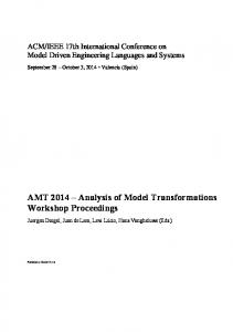
This section presents our approach for adding aspect-oriented modeling support to UML. A UML profile is developed as part of our framework to facilitate the specification of aspects using UML constructs. An aspect in our framework is a stereotyped package that contain a set of adaptations describing the different modifications that an aspect perform on the base model. An adaptation is represented as a stereotyped class that can be of two types: Structural adaptation or Behavioral adaptation.
Adaptation [Class]
stereotypes and tagged values defined in our profile for specifying adaptation rules together with the relations between them. For more details regarding our AOM profile, we refer the reader to [17].
Aspect [Package]
StructuralAdaptation [Class]
BehavioralAdaptation [Class]
ClassAdaptation [Class]
StateMachineAdaptation [Class]
SequenceAdaptation [Class]
ActivityAdaptation [Class]
3
Figure 1: Meta-Language for Specifying Aspects and their Adaptations.
Structural adaptations describe the modifications that affect structural diagrams, while behavioral adaptations specify modifications that target behavioral diagrams. Figure 1 present our meta-language for specifying aspects and their corresponding adaptations. Note that an adaptation is specified as a stereotyped class. Add [Operation]
0..*
1
Name:String Type:ElementType Position:PositionType
Pointcut [Operation]
1
Remove [Operation]
0..*
ElementType
0..* ClassElementType Class Property Operation Association Package
PositionType
BehavioralElementType
0..* 0..* StateMachineElementType SequenceElementType State Transition StateMachine Region
Lifeline Message Interaction InteractionUse
In this section, we present a new framework for weaving aspects into UML models. Aspects are defined as general concerns that can be reused across different applications. In the following subsections, first we describe the general architecture of our transformation tool. Next, we present the different transformation definitions and rules developed to transform UML models. Finally, we show the steps of the weaving process needed to weave aspects into UML models.
3.1
TextExpression: String OCLExpression: String
StructuralElementType
A Framework For Weaving Aspects into UML Models
Before After Around
0..* ActivityElementType Action Activity StructuredActivityNode ControlFlow
Figure 2: Meta-Language for Specifying Adaptation Rules.
Weaving Engine Architecture
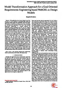
In this section, the general architecture of our aspect weaver is presented. The proposed aspect weaver, as shown in Figure 3, consists of two main components: (1) Transformation module, (2) Join point matching module. The transformation module is composed of four different transformation definitions, each of which is responsible of transforming a given UML diagram. Each transformation definition contains a set of mapping rules which define how each element in the corresponding diagram is transformed. Transformation Engine
Each adaptation in the aspect contains a set of adaptation rules and pointcut expressions. The adaptation rules describe the kind of modification that need to be performed, while the pointcut expression reference the location in the base model where the modification need to be applied. In our approach, we support two types of adaptation rules: adding and removing of UML elements. Pointcut expressions are defined using a textual expression language defined as part of our framework. Our defined pointcut language uses UML specific designators in order to capture different UML elements as join points. Figure 2 presents the different
UML Base Model
Class Transformation Definition
Sequence Transformation Definition
QVT Engine Aspect Model
Activity Transformation Definition
Woven Model State Machine Transformation Definition
Black-Box Mechanism For Join Point Matching
Figure 3: Weaving Engine Architecture. These mapping rules are defined based on the UML meta-elements which make the trans-
formations reusable with any UML model and are not dependant on a particular specification or implementation. Join point matching module is defined by extending the QVT engine through the QVT/Black-Box mechanism [3]. Black-Box mechanism is an important feature of the QVT language that facilitates the integration of external programs, expressed in other languages, to perform a given task that is un-realizable by the QVT language. To this end, we define a join point matching module as an extension to the QVT main functionality. This new feature allows evaluating pointcut expressions on UML base model elements and identifying the appropriate join points that satisfy the given expression.
3.2
Transformation Definitions
Transformation definitions describe how each element in the source model is transformed in the target model. For each defined aspect adaptation, we specify a corresponding transformation definition. By analogy, the aspect adaptations are program source code and the transformation definitions are its execution semantics. In other words, it defines how and when each construct in the aspect adaptation should produce a given behavior. Currently, our transformation engine consists of four transformation definitions: • Class Transformation Definition is a structural transformation that is designed to handle transformations of class diagrams. It alters the structure and hierarchy of class diagram elements. For each adaptation rule specified inside the class adaptation of the aspect, an equivalent mapping rule is applied. The weaving operation of class transformations simply injects the new element in the location identified by the pointcut expressions. • State Machine Transformation Definition is a behavioral transformation that deals with state machine diagrams. In our approach, join points can be either states, or transitions. Additionally, we identify two kinds of pointcut designators: (1) statebased pointcut, and (2) path-based pointcut. A state-based pointcut is used to
designate a set of states statically without any consideration of the transitions or events that were triggered to reach them, whereas a path-based pointcut designates a set of states dynamically by considering the transitions that triggered them. • Activity Transformation Definition is a behavioral transformation that aims at transforming activity diagrams. In our approach, join points in an activity diagram can be either an activity node, or an edge. The activity node is either an executable node (e.g., action, structured activity) or a control node (e.g., fork/join, decision/merge). Similarly, the edge is either a control flow or an object flow. • Sequence Transformation Definition is a behavioral transformation that aims at transforming interaction diagrams. In our approach, we consider sequence diagram messages as join points, where new behavior may be added before/after/around the occurrence of send/recieve message events.
3.3
Weaving Mapping Rules
As mentioned earlier, two adaptation rules are supported in our approach: add and remove. Additionally, the replace operation is realized by combining the two operations: remove, and then add. When weaving UML elements we classify them into three main categories: (1) Simple elements, (2) Composite elements, and (3) Two-end elements. Simple elements are UML elements that are compact. In other words, when manipulating them you deal with single atomic element. Composite elements are those elements that are composed of other elements or contain references to other UML element. Two-end elements are those elements that connect two UML elements together. Table 1 summarizes all the supported elements according to their categories. Before describing the set of defined mapping rules, first it is necessary to introduce the main operators defined by the QVT language: • “Map” Operator: It is used to apply an operation, or what is called mapping rule, on a single element or a set of elements.
Table 1: Classification of the Supported UML Elements. UML Diagram Class Diagram
State Machine Diagram
UML Element
Category Type
Package Class Operation Property Association State Machine Simple State Submachine State
Composite Composite Simple Simple Two-end Composite Simple Composite
Transition Region
Two-end Composite
• “→” Operator: It is used to iterate on collections of elements. When combined with the map operator, it facilitates the access to each element in the collection in order to apply the mapping rule to them. • “ · ” Operator: It can be applied to single elements to access their properties or operations. • Rule 1: Add Mapping Rule Add mapping rule is called on all adaptation rules in the aspect that are stereotyped with the stereotype ≪add≫. It is important to mention here that the order of adaptation rules, as specified by the aspect designer in each adaptation of the aspect, is preserved during the weaving. OrderedSet{addAdaptationRules} → map addMappingRule(); The above expression illustrates how the add mapping rule is applied to each element of the input ordered set of add adaptation rules extracted form the aspect. For each add adaptation rule in that sequence, the values of its properties or tagged values are read to further determine the next mapping rule to be invoked. In fact, the value of the property type determines the appropriate add subrule to be performed. In addition, the name of the new element to add is identified by the value of the tagged value name. The tagged value position of the “add adaptation” rule references the position where to add the new element in contrast with other existing elements in the base model. For instance, it indicates whether to add the new element before, after, or around the identified join point element. In the case of structural adaptation, the value of the property position is set to its default
UML Diagram Sequence Diagram
Activity Diagram
UML Element
Category Type
Interaction Interaction Use Lifeline Message
Composite Composite Simple Two-end
Activity Action Structured Activity Control Flow Object Flow
Composite Simple Composite Two-end Two-end
value inside and therefore is not taken into consideration during the weaving. Finally, the value of the tagged value pointcut is passed to the join point matching module to identify the set of join point elements. Depending on the type of the element to add and its category, the appropriate add subrule is applied to each element in the join point elements set. – Rule 1.1 Add Simple Element(elemName, position) This mapping rule is applied to each join point element that was previously identified. It takes two parameters: elemName the name of the simple element to add, and position the position where to add the element. This mapping rule creates the appropriate meta-element object and sets its name to the value passed in the parameter elemName. Depending on the value of position the newly created element is placed in the base model accordingly. object simple-meta-element {name:= elemName} – Rule 1.2 Add Composite Element(elemName, position) Add composite element mapping behaves in a similar way to the add simple element rule. However, it extends its behavior by adding a check for the elements that the new element should compose. In the case of interaction use element, for example, a reference to the composed interaction behavior needs to be identified. Thus, the mapping rule iterates through the enclosed elements of the aspect and selects the behavior that matches the name of the element to add. Finally, the selected element is copied to the base model and the composite element is created.
behElem:=Set{aspectElem}→ Select(el where el.name=elemName);
must be followed by an add operation that either replaces the removed element or corrects any of the arising issues.
object composite-meta-element {name:=elemName;refersTo:=behElem;};
Another use of the remove mapping rules is to support reverse transformation. In fact, one of the important properties of any transformation is bi-directionality. In other words, to be able to generate the base model back from the woven model. To do so, the inverse of each applied mapping rule must be applied to the generated woven model. Since the aspect is constructed by two basic operators; add and remove where each one of them is the logical inverse of the other. Therefore, in order to achieve bi-directional transformation, the inverse of each individual add mapping rule has to be provided as part of the transformation as well.
– Rule 1.3 Add Two-End Element(elemName, position, sourceExp, targetExp) Dealing with two-end element is different than any simple element as it requires the specification of the source and target of that element. When specifying an adaptation rule for a two-end element, two additional pointcuts are needed: one to select the source, and one to select the target. These two pointcuts are specified as parameters for the add adaptation, such that the first parameter represents the source pointcut, whereas the second parameter represents the target pointcut.
• Rule 3: Tagging Mapping Rule Tagging mapping rules are used to trace the performed modifications on UML base models. Each element that has been added or modified by the transformation needs to be easily identified in the woven model. To do so, the tagging mapping rule tags each element affected by the transformation by applying a special keyword to it. When the transformation executes and the woven model is generated, the affected elements can be easily distinguished in the woven model by having either ≪ AddedElement≫ or ≪ModifiedElement≫ keyword applied to them.
Set{sourceElem}:=Set{baseModelElem}→ joinPointMatching(sourceExp); Set{targetElem}:=Set{baseModelElem}→ joinPointMatching(targetExp); object two-end-meta-element {name:=elemName; source:=sourceElem;target:=targetElem;} • Rule 2: Remove Mapping Rule Remove mapping rule is applied to each adaptation rule in the aspect stereotyped with ≪remove≫ stereotype. It reads the value of the tagged value pointcut and passes it to the join point matching module to identify the set of elements that need to be removed. Unlike the additive rules, the type of the element to remove is not important. Thus, there is only one general rule to remove any type of UML element. Each identified join point element is removed using the destroy() method. Set{elemToRemove}:=Set{baseModelElem}→ joinPointMatching(pointcut); Set{elemToRemove} → destroy(); Indeed, the remove operation is very sensitive and should be dealt with cautiously, otherwise it may result in an incorrect UML woven model. For instance, removing a state in a state machine diagram without reconnecting its predecessor with its successor may result in two disconnected state machines. Therefore, the assumption here is that when designing an aspect in case of any remove operation, it
3.4
Aspects Weaving
In this section we describe the main steps followed in our approach to weave aspects into base models. First the aspect model is parsed in order to identify each kind of different adaptations. For each adaptation kind, the set of adaptation rules are extracted while preserving the order in which they are specified. The order is important to avoid conflicts between dependant adaptation rules. For each adaptation rule, the following steps are performed. • OCL Expression Generator In this step, pointcut textual expressions are translated into a language that can navigate the base model and select the considered join points. In our approach, we chose to translate the pointcut expressions into the stan-
dard OCL language. Basically, OCL is defined as part of the UML standard and is typically used to write constraints on UML elements. Since OCL 2.0, it has been extended to include support for query language. Additionally, OCL is known for its expressiveness, thus, it can be used to designate any UML element. The translation is done by producing a parser that is capable of parsing and translating any textual pointcut expression, that conforms to its defined grammar, to its equivalent OCL expression. Indeed, this process is executed automatically and in a total hidden way from the user. • Join Point Matching This process iterates through the base model elements and evaluates the given OCL expression on them in order to select the matched join points. However, dealing with big models with large set of elements can represent an overhead on the system if we attempt to evaluate the OCL expression on each single element. To solve this issue, instead of iterating through all the elements of the base model some filtering operations are performed. Since each pointcut element belongs to a specific adaptation kind, we filter the base model such that we only iterate through base model elements that conform to a given adaptation kind. For instance, a pointcut element, defined inside a state machine adaptation, designates elements of state machine diagrams. Thus, the filtering mechanism selects from the base model the elements that conform to the state machine diagram and passes them to the join point matching module. Indeed, This optimization increases the efficiency and the performance of the matching module. • Actual Weaving The actual weaving is performed by applying the different transformation definitions and executing the appropriate mapping rules. At this point, OCL expressions are generated from the predefined textual pointcuts. Since OCL is typically a constraint language, the generated OCL expressions are further used during the weaving to add more con-
straints on the identified join points. State1
State2 a) before Weaving
State1 Tr1 State4
Tr1 State3
Tr2 Tr3
Tr2 State2
Tr3
State3
b) after Weaving
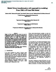
Figure 4: Weaving Example for Path-Based Join Point. For example, consider the state machine base model depicted in Figure 4 part (a), where we want to add a new state, State4, before state State3 when triggered by transition Tr1. To do so, the following OCL pointcut expression is needed: self.oclIsTypeOf(State) and self.name=‘State3’ and self.incoming → exists(t:Transition | t.name=‘Tr1’)
During the join point matching process, the OCL expression is evaluated on the base model elements and will return the element State3 as the identified join point. Then, the weaving process adds the new state State4 before the identified join point. However, if the state State3 has more than one incoming transition, which is the case in our example, the weaver will add the new state State4 before all incoming transitions which is not what we aim for. Thus, to solve this problem, the OCL expression is used not only as a query language to identify the join points during the matching process, but is also used to put further constraints on the identified join points during the weaving. To this end, our identified join point is state State3 under the constraint of being triggered by transition Tr1. The result of the weaving is shown in Figure 4 part (b). There are three weaving operations that are supported in our framework: – Weaving before (resp. after) operations into behavioral models requires not only identifying the join point itself but also its direct predecessor(s) (resp. successor(s)). In the case of activity and state machine diagrams, as they both are constructed from nodes and edges, the incoming
(resp. outgoing) edge to (resp. from) the identified join point is redirected to the new element that need to be added. This is done, by setting the target for that edge to the new node and then creating a new edge between the new node and the join point (resp. the join point original successor). As for sequence diagrams, the process is slightly different because of the special nature of message ordering in UML sequence diagrams. Ordering in interaction diagrams is realized by a trace of event occurrences, where each event is specified by a unit called occurrence specification. Occurrence specifications are ordered along a lifeline and each unit references the occurrence of a specific event [1]. We are interested particularly in the send and receive events of the exchanged messages. In the case of a before (resp. after) weaving, the send (resp. receive) event of the join point message is identified from the trace of events in order to insert the new element just before (resp. after) it. Algorithm 1 presents the algorithm used for weaving before adaptations in activity and state machine diagrams. The algorithm takes as input the new node to add, the ocl expression associated with the current “add adaptation” rule, the base model, and the set of the identified join points. The algorithm returns the woven model as output, where the new node has been added before all of the identified join points. – Weaving around operations into behavioral models requires injecting the adaptation in place of the join point they operate over, rather than before or after it. Additionally, within the behavior of the around adaptation, the original join point can be invoked with a special element named proceed. In the case where the new element to add is a simple element or twoend element, the around adaptation have the effect of replace. However,
Algorithm 1: Weaving Before Adaptation in Activity and State Machine Diagrams Input: newN ode, OCLExp, BaseM odel, joinP ointElem− set edgeSet: Edge-set; for nextJoinP oint in joinP ointElem − set do if nextJoinP oint is of type Node then if isPathBased(OCLExp) then oclConstraint = extractConstraint(OCLExp); edgeSet = getInComingEdge(nextJoinP oint, oclConstraint); else edgeSet = getInComingEdges(nextJoinP oint); end if if nextJoinP oint is of type JoinNode or MergeNode then for all edge in edgeSet do copy newN ode; edge.setTarget(newN ode); BaseM odel += CreateEdge(newN ode, nextJoinP oint); end for else for all edge in edgeSet do edge.setTarget(newN ode); end for BaseM odel += CreateEdge(newN ode, nextJoinP oint); end if else if nextJoinP oint is of type Edge then temp = getSource(nextJoinP oint); nextJoinP oint.setSource(newN ode); BaseM odel += CreateEdge(temp, newN ode); end if end for
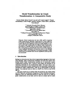
if the new element to add is a composite element there are two cases: (1) The composite element does not contain a proceed element inside its behavior, then the around adaptation replaces the original join point completely. (2) The composite element contains a proceed element inside its behavior. In this case, all elements that appear before the proceed element are injected before the join
point, and similarly all elements appearing after the proceed element are injected after the join point. The use of the around operation with proceed facilitates the specification of different crosscutting concerns that are not realized by other operations (i.e., before and after). For instance, crosscutting concerns that need to be weaved in parallel with some join points can be specified using the around with proceed operation. For example, consider the traditional scenario of placing an order depicted in Figure 5 part (a), where we want to add a new action that notifies the user while his/her order is being shipped. To do so, an around adaptation, presented in Figure 5 part (b), is needed. In order to weave the around adaptation we replace the proceed element in the around behavior with the identified join point. After that, the entire behavior is encapsulated in a single element that replaces the original join point in the base model as shown in Figure 5 part(c).
a) Base Model
Join point
b) Around Adaptation proceed
Place Order
Make Payment
Shipment
Delivery NotifyUser
ShipandNotify
c) Woven Model Place Order
Make Payment
Shipment
Delivery
NotifyUser
Figure 5: Example: Placing Order Activity Diagram. we need to introduce the notation that is used along this paper. Notation • The notations are written with respect to the OCaml notations [19]. • Given a record space D = ⟨f1 : D1 , f2 : D2 , . . . , fn : Dn ⟩ and an element e of type D, the access to the field fi of an element e is written as e.fi . • Given a type τ , we write τ -set, τ -uset, τ -list to denote the type of sets having elements of type τ , to denote the type of sets having a unary element of type τ , to denote the type of lists having elements of type τ , respectively. • The type Identifier classifies identifiers.
4
Formalization
In this section, we present a formalization of the matching and weaving processes in UML activity diagrams. First, we present a syntax for UML activity diagrams and UML aspects. Then, we define formal semantics for aspect matching and weaving. Additionally, we prove the correctness and the completeness of the weaving in UML activity diagrams. To do so, we define algorithms that implement the matching and the weaving semantics then we prove the correctness and the completeness of the matching and weaving processes with respect to the provided semantics and algorithms. However, for space limitation we make the algorithms and proofs available in [2].
4.1
Syntax
This section presents the syntax of UML activity diagram and its associated aspects. First,
An activity diagram, as shown in Figure 6, consists of a set of nodes and a set of edges. An edge is a directed connection between two nodes represented by source and target. In addition, an edge may have a guard condition specifying if the edge can be traversed. A node can be either an executable node (e.g., action, structured activity) or a control node (e.g., initial, final). An aspect, as depicted in Figure 7, includes a list of adaptations. We support two kinds of adaptations add and remove adaptations. An add adaption specifies the insertion point and the activity element to be injected at specific locations picked out by pointcuts. The insertion point of an adaption specifies where the activity element should be injected according to a specific location. The element to be added to the activity can be either a simple element (action) or a composite element (structured activity). We consider the following kinds of basic pointcuts: initial, final, flowfinal,
Activity
::=
: , : , edges :Edge-set⟩
⟨name Identifier
ForkDecision
nodes Node-set
Node
::=
Initial | Final | Action | ForkDecision |
JoinMerge
JoinMerge | StructuredActivity Initial
::=
:
⟨type initial
,
:
name Identifier
,
StructuredActivity
:
outgoing Edge-uset⟩ Final
::=
:
⟨type final | flowfinal
:
name Identifier
,
,
:
incoming Edge-uset⟩ Action
::=
:
⟨type action
,
:
, : , outgoing :Edge-uset⟩ name Identifier
Edge
incoming Edge-uset
::= ⟨type :fork | decision, name :Identifier, incoming :Edge-uset, outgoing :Edge-set⟩ ::= ⟨type :join | merge, name :Identifier, incoming :Edge-set, outgoing :Edge-uset⟩ ::= ⟨type :structuredactivity, name :Identifier, incoming :Edge-uset, outgoing :Edge-uset, nodes :Node-set, edges :Edge-set⟩ ::= ⟨name :Identifier, source :Node, target:Node, guard :true | false⟩
Figure 6: Activity Diagram Syntax Aspect
∋
s
Adaptation
∋
ad
::= ::=
Adaptation-list
::=
: : pos : pcd : ⟨kind : pcd : true ⟨kind
elem
|
Pcd
∋
p
|
¬p
|
p ∧ p
|
⟨kind
:
add
, ,
Action | StructuredActivity before | after | around
,
Pcd⟩ remove
,
Pcd⟩
initial | final | flowfinal | action | fork | join | decision | merge | inside_activity
name
:
,
Identifier⟩
Figure 7: Aspect Syntax action, fork, join, decision, merge, and inside_activity. These basic pointcuts can be combined with logical operators to produce more complex ones. A remove adaptation includes a pointcut that picks out the elements that should be removed from the activity diagram.
4.2
Matching and Weaving Semantics
In this subsection, we present the matching and the weaving semantics in activity diagrams. The matching semantics describes how to identify the join points targeted by the activity
adaptations. The weaving semantics describes how to apply the activity adaptations at the identified join points.
4.2.1
Matching Semantics
We define the judgment A, n ⊢match pcd, which is used in the matching semantic rules presented in Figure 8, to describe that a node n belonging to the activity A matches the pointcut pcd. A node n can be initial node i, activity final node af, flow final node ff, action node a, fork node f , join node j, decision node d, merge node m, or either of these nodes sn.
pcd.kind = initial
pcd.name = i.name
pcd.kind = final
A, i ⊢match pcd pcd.kind = flowfinal
pcd.name = ff .name
pcd.kind = action
A, ff ⊢match pcd pcd.kind = fork
pcd.name = a.name
A, a ⊢match pcd
pcd.name = f.name
pcd.kind = join
A, f ⊢match pcd pcd.kind = decision
pcd.name = af .name
A, af ⊢match pcd
pcd.name = j.name
A, j ⊢match pcd
pcd.name = d.name
pcd.kind = merge
A, d ⊢match pcd
pcd.name = m.name
A, m ⊢match pcd
pcd.kind = inside activity
A, n ⊢match pcd1
.
pcd.name = A name
A, n ⊢match pcd2
A, n ⊢match pcd1 ∧ pcd2
A, sn ⊢match pcd A, n ⊢match pcd1
A, n ⊢match pcd2
A, n ⊢match pcd1 ∨ pcd2
A, n ⊢match pcd1 ∨ pcd2
A, n 0match pcd A, n ⊢match ¬pcd
Figure 8: Matching Semantics 4.2.2
Weaving Semantics
The weaving semantics presented in Figure 9 is represented by the weaving configuration ⟨Activity, Aspect, Node, State⟩. The state State is a flag that represents the stage of the adaptation weaving process, which is either weaving or end. The flag is equal to weaving when adaptations still have to be woven whereas it becomes end when the weaving is completed. Hence, the transformation ⟨A, s, n, weaving⟩ ,→ ⟨A′ , s′ , n′ , end⟩ means that the activity diagram A′ is the result of weaving all the applicable adaptations in the adaptation list s into the node n. We define a function builtEdge that takes two nodes as inputs and returns an edge between these two nodes: builtEdge : Node × Node → Edge builtEdge(s, t) = e where (e.source (e.target = t)
5
=
request login page from LoginManager class and then calls the Login method with his username and password. The LoginManger then validates the user credentials by contacting the AccountManager class. If the user credentials are valid, then the loginManager requests the user’s profile from ProfileManager class, and returns the user’s homepage to the client (See Figures 10, 11). The current login mechanism is vulnerable to different kinds of security threats, such as man-in-the-middle attacks, where an attacker may intercept the user’s credentials, as they are sent in plain text, and impersonate the user. To fix this problem, we replace the current login authentication mechanism with a certificate-based authentication using TLS protocol [7].
s) ∧
Case Study
In this section we present a case study to demonstrate the feasibility of our approach. Our case study, which is adopted from [12], presents a social networking application which has a generic login process in place. Current login process only verifies the user’s username and password and either allows or blocks user access accordingly. In this scenario, a Client
Figure 10: Class Diagram for Social Networking Application - Base Model To do so, we specify a TLS aspect as presented in Figure 12. The TLS aspect is de-
s = ad :: s′
ad.kind = add
A, n ⊢match ad.pcd e′ = builtEdge(ad.elem, n)
n.type ̸= initial
ad.pos = before
es = n.incoming e ∈ es e.target = ad.elem ad′ = {ad with elem.incoming = e, elem.outgoing = e′ }
n′ = {n with incoming = (es\{e}) ∪ {e′ }} no = A.nodes ed = A.edges A′ = {A with nodes = (no\{n}) ∪ {n′ , ad′ .elem}, edges = ed ∪ {e′ }}
(Before)
⟨A, s, n, weaving⟩ ,→ ⟨A′ , s′ , n′ , weaving⟩ s = ad :: s′ ad.kind = add ad.pos = after n.type ̸= final n.type ̸= flowfinal A, n ⊢match ad.pcd os = n.outgoing e ∈ os ad′
next = e.target e′ = builtEdge(ad.elem, next) = {ad with elem.incoming = e, elem.outgoing = e′ }
e.target = ad.elem es = next.incoming
(After)
next.incoming = (es\{e}) ∪ {e′ } no = A.nodes ed = A.edges A′ = {A with nodes = no ∪ {ad′ .elem}, edges = ed ∪ {e′ }} ⟨A, s, n, weaving⟩ ,→ ⟨A′ , s′ , n, weaving⟩ s = ad :: s′ n.type = action
� ad.elem e′ ∈ n.outgoing
ad.kind = add ad.pos = around A, n ⊢match ad.pcd e ∈ n.incoming
e.target = ad.elem e′ .source = ad.elem no = A.nodes ′ ad = {ad with elem.incoming = e, elem.outgoing = e′ }
(Around1 )
A′ = {A with nodes = (no\{n}) ∪ {ad′ .elem}} ⟨A, s, n, weaving⟩ ,→ ⟨A′ , s′ , ad′ .elem, weaving⟩ s = ad :: s′
ad.kind = add
ad.pos = around
ad.elem.type = proceed str activity
ad.elem n.type = action A, n ⊢match ad.pcd e ∈ n.incoming e′ ∈ n.outgoing ′ e.target = ad.elem e .source = ad.elem pr ∈ ad.elem.nodes pr.type = proceed e1 ∈ pr.incoming e2 ∈ pr.outgoing e1 .target = n e2 .source = n n′ = {n with incoming = e1 , outgoing = e2 } no = ad.elem.nodes
(Around2 )
ad′ = {ad with elem.nodes = (no\{pr}) ∪ {n′ }, elem.incoming = e, elem.outgoing = e′ } no′ = A.nodes A′ = {A with nodes = (no\{n}) ∪ {ad′ .elem}} ⟨A, s, n, weaving⟩ ,→ ⟨A′ , s′ , ad′ .elem, weaving⟩ s = ad :: s′ ad.kind = remove e ∈ n.incoming e′ ∈ n.outgoing no = A.nodes
n.type = action next = e′ .target
A, n ⊢match ad.pcd e.target = next
ed = A.edges es = next.incoming next.incoming = (es\{e′ }) ∪ {e} ′ A = {A with nodes = no\{n}, edges = ed\{e′ }}
(Remove)
⟨A, s, n, weaving⟩ ,→ ⟨A′ , s′ , next, weaving⟩ s = ad :: s′
A, n ⊢match ¬ ad.pcd
⟨A, s, n, weaving⟩ ,→ ⟨A, s′ , n, weaving⟩ s=[ ] ⟨A, s, n, weaving⟩ ,→ ⟨A, [ ], n, end⟩
(NoMatch)
(End)
Figure 9: Weaving Semantics signed using our defined UML extension for Aspect-Oriented Modeling [17]. The aspect defines two kinds of adaptations: class adaptation, and sequence adaptation. The class adaptation adds the different attributes needed by
the TLS protocol (e.g., nonce, public/private keys, certificates, etc.) to the Client and LoginManager classes. Additionally, it removes the current login method and replaces it with a secure one. The sequence adaption on the
Figure 11: Sequence Diagram Representing the Login Interaction - Base Model other hand, adds the interaction behavior that specifies the TLS protocol (Figure 13). This is accomplished by defining an adaptation rule AddSecureLogin which specifies to inject the secure login behavior as an interaction use around any call to the login method picked out by the pointcut LoginPointcut.
Figure 12: TLS Aspect The first step of the weaving is the automatic identification of the join points where the secure login behavior (Figure 13) should be injected. To achieve this, our framework first translates the textual expression of the pointcut LoginPointcut to its equivalent OCL expression. This step is done automatically and in a total transparent way from the user. The resulting OCL expression is as follows:
Figure 13: Sequence Diagram Representing Secure Login Interaction based on TLS Protocol self.oclIsTypeOf(Message) and self.name= “Login” and (self.messageSort= MessageSort::synchCall or self.messageSort= MessageSort::asynchCall) and self.connector. end->at(1).role.name=“Client” and self.connector. end->at(2).role.name=“LoginManager” Then, the join point matching module evaluates the generated OCL expression and returns all the message calls to the login operation as join points. For instance, in the example of Figure 11, the message call Login is selected as a matched join point. The last step of the weaving is the automatic injection of the secure login behavior into the base model at the identified join points. This is achieved by executing the QVT mapping rule that corresponds to the adaptation rule AddSecureLogin (See Figure 12). Finally, the resulting woven model is automatically generated (Figures 14 and 15).
6
Related Work
Various approaches have been published recently proposing different techniques for weaving aspects into design models, the following is an overview of these approaches. XWeave [13]
graph rule using a graph rule execution tool. GeKo (generic composition with kermeta) [16] uses a Porolog-based pattern matching engine implemented in Kermeta [18, 20] to automatically identify join points. MATA [21] supports the composition of class, sequence, and state machine diagrams. The base model is transformed into a graph, and the MATA model is transformed into AGG graph rule that is executed on the base graph automatically. Then, the result is transformed back to UML model.
Figure 14: Sequence Diagram Representing the Secure Login Process - Woven Model
Figure 15: Social Networking Application Class Diagram - Woven Model is a model weaver that is able to weave both models and meta-models. Pointcuts used by XWeave are expressed using oAW, an expression language based on OCL. XWeave only supports additive weaving. The removal and replacement of base model elements are not supported. Motorola weaver [22] is a model transformation engine that enables weaving aspects into executable UML state machine models. It supports two types of join points: actions and transitions. However, this weaver is based on the Telelogic TAU G2 implementation which makes it tool-dependent and not portable. In [16, 21] two AOM approaches based on graph transformations called GeKo and MATA are presented respectively. Both support structural and behavioral composition. However, the composition or weaving is not done on UML models directly, but rather is executed as a
Fleurey et al. [10] have presented a generic tool for model composition called Kompose, which is built on top of Kermeta. It focuses only on the structural composition of any modeling language described by a meta-model. Thus, it does not support behavioral composition. In addition, it adopts a signature comparison mechanism to match elements during the weaving, which makes the specified aspects application specific rather than generic. The ATLAS Model Weaver(AMW) [9] has been developed by the ATLAS group, INRIA for establishing relationships, i.e., links between models. These links are stored in a model called weaving model. AMW requires continuous interaction with the developer to build the weaving model, thus, it does not support automatic weaving. Fuentes and S´anchez [11] have proposed an approach for designing and weaving aspect-oriented executable UML models. A UML profile is presented to support aspectoriented concepts along with a model weaver for such profile. The weaving process is defined as a chain of model transformations. However, no model transformation language is used. Instead, Java and standards like XSLT and XPath are used to directly manipulate the XMI representation of the models which raises some scalability and maintenance problems. Cui et al. [6] propose an aspect-oriented modeling approach for modeling and integrating UML activity diagrams. Two types of crosscutting concerns are handled: parallel and sequential crosscutting concerns. Parallel aspects are uncritical features that their execution does not affect the behavior of the primary model. Sequential aspects on the other hand are critical features that their execution results may influence the processes in the primary model. Hovsepyan et al. [14] have proposed an approach
called GReCCo for composing concern models. Different concerns are specified as generic concerns independent of any context to support reusability of concerns. A composition model is specified with the appropriate directions to the transformation engine on how to compose the two models. For each composition operation a separate composition model is specified which may be a costly task in terms of effort and complexity.
7
Conclusion
In this paper, we have presented an aspectoriented approach for weaving crosscutting concerns into UML models. We have instrumented OCL language for join point matching. Aspect weaving into UML diagrams has been implemented using QVT operational language. Furthermore, we have formalized the matching and weaving semantics in Activity diagrams. The defined approach supports wide range of UML diagrams and considers a variety of modifications and join points. Additionally, it is portable and expressive thanks to the standards OCL and QVT. Traceability of the performed weaving operations are supported through the tagging rules for the added and modified elements. As a future work, we plan to focus on the traceability mechanisms of the removed elements. Additionally, we plan to extend the weaving semantics to other UML diagrams.
References [1] Unified Modeling Language (OMG UML): Superstructure, Version 2.2, 2009.
[7] T. Dierks and C. Allen. RFC2246: The TLS Protocol (TLS), 1999. [8] T. Elrad, R. E. Filman, and A. Bader. Aspectoriented Programming: Introduction. Communications of the ACM, 44(10):29–32, 2001. [9] Marcos Didonet Del Fabro, Jean Bezivin, Frederic Jouault, Erwan Breton, and Guillaume Gueltas. AMW: A Generic Model Weaver. In Proc. of the 1re Journe sur l’Ingnierie Dirige par les Modles (IDM05). [10] F. Fleurey, B. Baudry, R. France, and S. Ghosh. A Generic Approach for Automatic Model Composition. In Models in Software Engineering: Workshops and Symposia at MoDELS 2007. [11] L. Fuentes and P. S´ anchez. Designing and Weaving Aspect-Oriented Executable UML Models. Journal of Object Technology, 6(7):109–136, 2007. [12] Geri Georg, Indrakshi Ray, Kyriakos Anastasakis, Behzad Bordbar, Manachai Toahchoodee, and Siv Hilde Houmb. An Aspect-oriented Methodology for Designing Secure Applications. Inf. Softw. Technol., 51(5):846–864, 2009. [13] I. Groher and M. Voelter. XWeave: Models and Aspects in Concert. In Proc. of the 10th International Workshop on Aspect-Oriented Modeling, pages 35– 40, New York, NY, USA, 2007. ACM. [14] A. Hovsepyan, S. Baelen, Y. Berbers, and W. Joosen. Generic Reusable Concern Compositions. In ECMDA-FA ’08: Proc. of the 4th European conference on Model Driven Architecture, pages 231–245. Springer-Verlag, 2008. [15] IBM-Rational Software Modeler. Available at http:// www.ibm.com/software/awdtools/modeler/swmodeler/. ez´ equel. A [16] B. Morin, J. Klein, O. Barais, and J. M. J´ Generic Weaver for Supporting Product Lines. In EA ’08: Proc. of the 13th international workshop on Early Aspects at ICSE’08, pages 11–18, New York, NY, USA, 2008. ACM. [17] D. Mouheb, C. Talhi, M. Nouh, V. Nune, M. Debbabi, L. Wang, and M. Pourzandi. AOM for Representing and Integrating Security Concerns in UML. Springers Studies in Computational Intelligence, 2010. [18] P. A. Muller, F. Fleurey, and J. M. J´ ez´ equel. Weaving Executability into Object-Oriented Meta-Languages. In Proceedings of MODELS/UML’2005, volume 3713 of LNCS, pages 264–278, Montego Bay, Jamaica, 2005. Springer.
[2] ENCS Users’ Webpages, Concordia University, Montreal, Qc. Available at http://users.encs.concordia. ca/~d_mouheb/appendix.pdf, 2010.
for Scientists. Available [19] OCaml http://caml.inria.fr/pub/docs/manualocaml/index.html. 2010.
[3] MOF Query/View/Transformation, Version 1.0. Available at http://www.omg.org/spec/QVT/1.0/, 2010. [4] Object Constraint Language, Version 2.2. Available at http://www.omg.org/spec/OCL/2.2/, 2010.
[20] R. Rodrigo, O. Barais, and J. M. Jzquel. Matching Model-Snippets. In In Proc. of ACM/IEEE 10th International Conference on Model Driven Engineering Languages and Systems (MoDELS 07), Nashville, TN, USA, 2007.
[5] AOM Workshop. http://www.aspect-modeling.org/. Last visited: April 2010.
[21] J. Whittle and P. Jayaraman. MATA: A Tool for Aspect-Oriented Modeling Based on Graph Transformation. In Workshop on AOM at MODELS 2007.
[6] Z. Cui, L. Wang, X. Li, and D. Xu. Modeling and Integrating Aspects with UML Activity Diagrams. In SAC ’09: Proc. of the 2009 ACM symposium on Applied Computing, pages 430–437, New York, NY, USA, 2009. ACM.
at
[22] J. Zhang, T. Cottenier, A. Berg, and J. Gray. Aspect Composition in the Motorola Aspect-Oriented Modeling Weaver. Journal of Object Technology. Special Issue on AOM, 6(7):89–108, 2007.