trace view, shows the textual record of the last PVM call in each task. Newer ... veloped at the Graphics, Visualisation, and Usability Centre at Georgia. Institute of ...
Aspects and Taxonomy of Program Visualisation M.J. Oudshoorn, H. Widjaja and S.K. Ellershaw
Department of Computer Science University of Adelaide Adelaide, South Australia 5005
Program visualisation focuses on the graphical representation of an executing program and its data. The information is presented in a form designed to enhance both the understanding and productivity of the programmer through the e�cient use of the human visual system. The programmer is able to observe patterns of behaviour within the executing code and rapidly detect a departure from the expected behaviour pattern. However, depending on the programming paradigms and architectural platforms utilized, the variety and manner in which information is best presented varies. This chapter attempts to discuss the general aspects of program visualisation, including the variety of purposes, the general steps needed to provide such visualisation, and the ideals that a program visualisation tool can achieve. The requirements for visualization systems also vary across architectural platforms, and software systems, which include programming paradigms and the system environment. Some representative visualisation systems are also presented and examined, providing an overall view of the practice and the achievements made to date in program visualisation.
1 Introduction When describing complex ideas, it is often useful to use pictures to convey meaning clearly and succinctly. An architect, for example, when involved in building a large structure will use a drawing or a blueprint to explain it to others. Pictures are not only important when describing a large amount of information, but also when trying to communicate mental models describing abstract ideas. A child can be taught about the concept of the number \4" by being shown four apples while a stock broker may understand the trends in price of a certain stock by viewing a graph of the changes over time. In these cases a mental model of an abstract concept is mapped to a visualization 1. The human ability to perceive pictorial representations quicker than textual representations can be used to help programmers understand the programs they write and use. A textual representation of program code can only lend limited insight into the behaviour of executing code. It is beyond human abilities to assimilate the sheer volume of information in many software systems in its textual form. Gaining an understanding can be a very slow and painful process, especially if the code was written by someone else. Methods of program visualization, also known as software visualization, are developed to facilitate the understanding of executing code.
Static Model
Run-Time Control
Dynamic Model
Programmer’s Control
Traditional & Program Visualisation Tools
Programmer’s Initial Mental Model
Programmer’s Execution Mental Model
Correspondence Searching
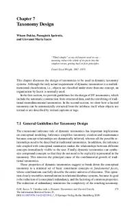
Figure 1: Model of a program development cycle.
Program visualisation can be de ned as the use of graphical artifacts to represent both the static and dynamic aspects of a program 2. Its main usage, in terms of program development cycle, is best described by Figure 1. First, a programmer creates a mental model of the software/program. This original mental model is then transformed into the corresponding static model using program development tools, such as text editors, CASE tools, and compilers. In this context, a static model comprises source code, the associated object code, and other intermediate code forms. After the static model is created, it is transformed into the corresponding dynamic model. This model refers to the run-time behaviour of the program. The transformation is done by using program environment run-time control, such as operating systems and run-time libraries. This dynamic model can furthermore be mapped into the programmer's execution mental model, which is a mental representation of the program execution. This mapping is important 3, because it enables the programmer to superimpose the execution mental model with the original mental model, which was conceived during the creation of the program. This makes it possible to understand, or debug the program. Several methods exist to derive an execution mental model of a program from the dynamic program model, including traditional software testing methods and reverse engineering. Generally, these methods heavily use non-graphical representations. As a result, a programmer may have to exert a considerable amount of e�ort to construct this execution model. By using program visualisation tools, this problem is alleviated. The reason is that the tools provide information through visual representation of program execution
or elements. Since pictorial information is generally easier to understand, the visual representation provides a framework from which programmers can derive their own mental models. In e�ect, this accelerates the whole process of software development. It is worth noting that the use of visualisation tools acts more as a complement to the use of other traditional software development tools, such as CASE tools, and textual debuggers. It does not intend to replace the use of these tools. Used in this way, program visualisation adds additional perspectives and greater understanding of the overall software or program. Based on the above discussion, the use of program visualisation is important. However, it is a relatively new eld, and much still has to be done to resolve existing and potential new issues 2 . Consequently, there exists no taxonomy that can completely identify and categorise tools and elements in program visualisation. Therefore, it is the aim of this chapter to introduce a simple, and extensible, taxonomy for the purpose. Several taxonomies dealing with program visualisation have been proposed. Price et al 2 have proposed a tree-based taxonomy that covers a wide range of general features in program visualisation tools. It includes the categorisation of input, output, and the processing therein, along with some metrics. This taxonomy can also be expanded to cover new categories. Another taxonomy scheme by Roman 4 tries to di�erentiate and categorise the elements and methods in providing visualisation of programs. This taxonomy is based on the notion that visualisation is a mapping from programs to graphical representations. Yet, another classi cation scheme is proposed by Kraemer 5 . It deals speci cally with each task of transforming the abstract execution of a program into its graphical representation. All of the above taxonomies have their own merits. However, they generally deal with the categorisation of tools in terms of how to provide a sensible visualisation scheme. The question of what to provide to the end user is not speci cally addressed. This chapter attempts to present another taxonomy from this perspective. It is the authors' belief that a complete and thorough taxonomy of program visualisation is dif cult to construct at the moment. Therefore, it is also the authors' intention to provide a taxonomy to complement the existing ones. This chapter is divided into several sections. Section 2 provides some examples of program visualisation systems. What and how they provide visualisation is discussed to give an overview of how program visualisation works, and how it can be devised. Section 3 describes some general aspects of program visualisation, followed by Section 4, which presents a general taxonomy based on architectural requirements and software domains in which program visualisation operates. The whole discussion is summarised in Section 5.
In the course of this discussion, it is assumed that the users of program visualisation tools are the software engineers who develop, or maintain a program.
2 Some Example Systems In order to have an understanding of program visualisation, and to provide better access to subsequent sections, several example program visualisation tools are discussed. There have been a number of program visualisation tools which are constructed for di�erent environments, and di�erent purposes. However, due to space limitations, this section only describes some representative systems. They are chosen here for the reasons of historical importance, for their wide usage, and for the various and diverse approaches they use. 1. BALSA BALSA 6 was the rst major program visualisation system available. Developed at Brown University, it is also one of the earliest systems to take advantage of graphical workstations and windowing systems. It is a toolkit for developing application-speci c visualisation and animation of algorithms. To produce animation, the original program or algorithm is rst annotated with calls to the BALSA \interesting events" manager. The calls are manually inserted at the points where changes to program states, such as data or data structures, occur. Views corresponding to the \interesting events" are then developed to re ect changes associated with the inserted calls. The advantage of using BALSA is that speci c views tailored to speci c algorithms can be developed. However, it means that only experienced or expert users can develop such views. BALSA is perhaps best used as a program visualisation and animation toolkit for designing views in the context of education and research. 2. Hence and XPVM Hence 7 and XPVM 8 9 are both tools for visualising the execution of PVM 10 programs. ;
�
Hence
Hence is a combination of visual progamming and program visualisation environments for PVM programs. As a visual programming environment, it provides tools to users for composing PVM
programs graphically. It also allows users to graphically specify the underlying machine con guration for the execution of the programs. Finally, based on a task graph and machine network graph, it automatically generates the nal PVM programs, compiles, and installs them on each of the machines. As a program visualisation tool, it collects traces from the execution of the PVM programs, and displays them graphically. The underlying machine network is displayed along with the lists of tasks mapped onto each of them. The user's original task graph is also displayed with changes to indicate the various activities in each task. Finally, it also shows a histogram of processor utilisation. Using Hence, users can understand the ow of execution within PVM programs more easily than solely through the use of textual information. To some extent, bottlenecks in the application can also be understood. �
XPVM
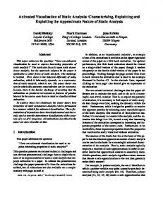
Unlike Hence, XPVM does not include a visual programming environment. Instead, it is used speci cally for visualising PVM programs. Trace data, which is used to drive the visualisation, is produced by PVM programs utilising tracing facilities in PVM libraries. The visualisation is performed concurrently (on-the- y) with the execution of the associated PVM programs. XPVM provides several views. The network view displays the virtual machine con guration and their activity status (by using colours). The space-time view shows the activities of individual PVM tasks on each virtual machine, at each point in time of its execution. XPVM also has some other views, which includes the view of task utilisation versus time. This view shows the percentage of tasks (from the overall number of tasks) involved in computation, communication wait, or overhead activities. Another view, the call trace view, shows the textual record of the last PVM call in each task. Newer versions of XPVM 9 include a display of message queues which show the number and size of messages bu�ered and waiting to be received for each task. Figure 2 shows the views in XPVM. In terms of functionality of program visualisation, XPVM is similar to Hence. However, unlike Hence, XPVM can visualise any PVM programs provided that PVM tracing libaries are used. Hence, on a
a From
http://www.netlib.org/utk/icl/xpvm/xpvm.html, courtesy of Dr. James A.Kohl
Figure 2: Tracing a program by using XPVM.
the other hand, can only visualise the programs constructed via its visual programming interface. 3. ParaGraph ParaGraph 11 is a program visualization tool developed at Oak Ridge National Laboratory in 1991, and is still widely used by the parallel programming community. It provides the user with a rich set of displays for message-passing parallel programs by showing valuable performance analysis information at an architectural level. Paragraph supplies over 20 di�erent displays, most of which can be categorised into one of three areas | utilisation displays, communication displays and task displays. ParaGraph uses a post-mortem approach to provide program visualisation. It takes as its input a trace le that conforms to the trace le format speci cation of the PICL 12 13 message-passing library. This trace ;
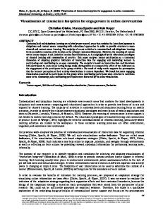
Figure 3: The Kiviat diagram from ParaGraph.
le represents the information of the execution of the original program, which can later be visualised. It encodes information, such as the interprocess communication, and processor loads at each point in time. The trace le is processed by ParaGraph to produce the three types of displays, as previously explained. These displays include, for example, the Kiviat diagram, the task computation time diagram, and inter-processor communication diagram. Figure 3 shows the Kiviat diagram from ParaGraph. It shows the utilisation of each processor as a point on the spokes of a wheel, with the hub representing zero (indicating being idle). Since ParaGraph only depends on the trace le as input, it can process other trace les produced by any other tools, as long as they conform to the PICL speci cation 14 . One drawback of Paragraph is that it does not have any mechanism to tie the displayed views back to the original program constructs or source-code. It is therefore di�cult for the user to relate the diagrams to the program code. 4. POLKA POLKA 15 is a general-purpose program visualisation toolkit that can be used to design application-speci c visualisation displays and views. Developed at the Graphics, Visualisation, and Usability Centre at Georgia Institute of Technology, its target is the visualisation and animation of the execution of thread-based and parallel programs. POLKA is based on the notion that users best know the types of displays that can help achieve the purpose of the visualisation.
Figure 4: The visualisation of the Tower of Hanoi by POLKA.
POLKA is developed in C++, and has 2-D and 3-D versions. It supports concurrent, and overlapping animation that can mimic the concurrent operation of the program being visualised. To use POLKA, the user manually instantiates several POLKA objects, and adds the associated object methods to drive the nal displays. Next, the original program is annotated with these object methods in places where interesting program abstractions or program events occur. The modi ed program is then compiled together with the POLKA library. When the program is executed, it drives the animation scenes, in addition to carrying out the original execution sequence. Figure 4 illustrates an example view of a POLKA program. POLKA is very useful because it provides the users with great exibility in choosing and designing their own views and displays. However, it also means that the users must know the details of the program being visualised, whereas often program visualisation is used to help users, who did not create the program, to understand it. POLKA is perhaps better used as a toolkit upon which other program visualisation tools can be built.
Ideals
Visualisation
Purposes
Mechanisms
Figure 5: Aspects of program visualisation.
3 Aspects of Program Visualisation Having described some representative program visualisation systems, this section discusses some general aspects of program visualisation, which include the purposes, ideals and the mechanisms through which program visualisation is devised (see Figure 5). 3.1 Purposes
Program visualisation is used for several purposes. These purposes serve to specify the nature of the corresponding searching between the programmer's initial mental model and the execution mental model (see Figure 1). In general, the purposes of program visualisation can be speci ed as follows. 1. Understanding Understanding the behaviour of a program is especially useful in the development and maintenance process. As described by DePauw 3, a visualisation tool that supports this purpose bridges the gap between the static speci cations and run-time behavior of a program. Either basic views or abstract high-level views are used. The work by De Pauw 3 16, and by Jerding 17 explore this purpose. 2. Debugging Debugging, which is to nd the di�erences between the initial program speci cation and the real program execution, can also be aided by program visualisation. When a visualisation display shows that the behaviour of a program is not as what the programmer expected, the debugging process can be well under way. ;
3. Performance Analysis Program visualisation can also be used for performance analysis. Such analysis is typically carried out on parallel programs, because performance is the raison d'^etre for parallel computation 18 . To be e�ective, performance visualisation tools should provide displays that give insight into the relationship between a program's performance characteristics and its structure and operation 19. Sometimes, several purposes are served together by a program visualisation tool. A tool which is used for debugging can also be used for understanding, for instance. 3.2 Ideals
The ideals of program visualisation generally di�er in each situation. However, since program visualisation is a relatively new eld, and it involves the use of graphics, these ideals are subjective. Nevertheless, several criteria can be established. These can also be used as a metric against which di�erent tools can be compared. The ideals may be incomplete, yet are su�cient in most cases. The ideals of a visualisation system can be roughly divided into two perspectives: the system's perspective, and the user's perspective. From the system's perspective, a visualisation tool has the following ideals. 1. Scalability The tool should be su�ciently scalable in terms of the problem size it can handle. For example, with a parallel program, the visualisation should be scalable in terms of the number of processors involved in the computation of the visualised program. 2. Extendibility Here, extendibility means that the concepts implemented in the tool should be exible enough to change, or to capture new concepts or ideas. Practically, this means that new views or displays can be added or changed relatively easily, for example. 3. Portability Portability means that either the tool itself (the program) or the concepts implemented in one platform do not obstruct its portability to other platforms. Minor changes are to be expected, because di�erent platforms
may require slightly di�erent implementations. A relatively high degree of such portability is a desirable property. From the user's perspective, a visualisation tool has the following ideals. 1. Minimal disturbances to the user's program Disturbances or probe e�ects induced or inserted in a program to be visualised is sometimes inevitable. However, it is desirable that they be kept to a minimum, in accordance with the goals to be achieved. 2. Little or no programmer's intervention The generation of visualisation events should be automated as far as possible so that little or no programmer's intervention is necessary. This requirement stems from the fact that manually generating a visualisation is both tedious and error-prone. It is also awkward to then visualise a program that is still currently under development. 3. Handle real-world problem One good way to test or measure a visualisation tool is to examine the size and nature of the problems it can handle. It is desirable that the tool can handle real-world problems. If this cannot be achieved, then at least an extended version of the tool should be able to achieve the same e�ects. 4. Present the \right" things to the user From the perspective of the user interface, a good visualisation tool provides its user with the \right" information, and in the \right" way. What constitutes the \right" information and display mechanism is subjective, but at least, the following guidelines generally hold. �
�
A visualisation tool should provide users with the most important and most useful aspects of a program. What is important and useful in a program depends on the goals to be achieved. One way to achieve this is to provide multiple views to show users multiple facets of a program. Uninteresting views can be skipped or deleted. The tool should behave as a good provider of feedback information. This means that visualisation should give information to the user, and not rationalise it. The visualisation should let the user discover things or details which are as yet unknown, rather than justify what the user expects.
Program Execution Instrumentation & Data Collection
Program Data Representation Post-processing
Visual (Intermediate) Data Representation Visualisation
Pictorial Representation
Figure 6: Transformation series to produce program visualisation. �
�
�
The visualisation should also incorporate su�ciently good aesthetics. However, the resulting graphical or display attributes should give users useful information, not merely serving as decorations. The visualisation can let users focus quickly on particular points of interest. This can be achieved by providing a \navigational map" or using hierarchical views to organise information. The visualisation should also provide good controllability over the views. This means that users are provided with su�cient control so that they can use the tool \in their own way". Speed control, playback mechanisms, and the \navigational map" are three such examples.
3.3 Mechanisms
Program visualisation is basically a product of a series of transformations of program execution data into its pictorial representation (see Figure 6). Here, program execution produces some program data representation to drive the nal visualisation process. This data representation is then transformed into an intermediate data representation which is ready to be visualised. Finally, this intermediate representation is transformed into the nal graphical output. The above-mentioned transformations are general and typical of most of the approaches to provide program visualisation. To facilitate the transformations, several steps are needed 5 20. These are described below. ;
1. Instrumentation and Data Collection Instrumentation is the rst phase in obtaining program data representation from program execution. Such data represents computation states of the program. This data is collected and processed further to derive proper visualisation displays. Instrumentation can be done, and typically is, by annotating either the original program or its run-time environment with \probe" statements. When the program is executed, these probe statements produce data representing program states (program data representations, or events) at each point of interest. Instrumentation, however, can cause perturbation within the monitored program, something which is sometimes inevitable 5 . Its minimisation, however, is highly desirable. Program instrumentation can be automatic or manual. When it is automatically done, users' programs are automatically augmented with probe statements. With manual instrumentation, users have to insert the statements themselves. 2. Post-processing The program data representation collected from the execution of the user's program is further processed to produce some internal data representation that re ects the nal graphical output. This post-processing may include reordering, clustering and ltering of the program data representation, resulting in the visual data representation, ready to be mapped to the display. 3. Visualisation The nal stage is to transform the visual data representation into its corresponding pictorial representation, in the form of graphical displays. Graph-based or statistics-based displays, or other types of visual representation can be used for this purpose. These displays typically represent the dynamic execution behaviour of the original user's program. Such displays can also be accompanied by displays of static program information, such as the source code display. In the nal displays, the program data representations can have several pictorial representations. These displays are typically divided into several well-known types, as follows. �
Graph-based displays
Graph-based displays are generally used for simulating, and representing program activities. Program entities are represented by
nodes which are in the forms of closed geometric gures, while their interactions are represented as edges. Zeus 21, Virtual Images 22, GraphTrace 23 , Ovation 3 16, and VizBug++ 17 fall into this category. The advantage of this approach is that it gives a direct, usually one-to-one, relationship between program activities and their display representations. As a result, it can easily be understood. ;
�
Statistics-based displays
This display type is usually used for showing performance data. The Kiviat diagram (see Figure 3), the Feynman diagram, bar graphs, matrix views, and charts in ParaGraph fall into this category. Tools such as PIE 24, Pablo 25 26 and TraceView 27, and XPVM use this display type to show performance data. ;
�
Source-code-related displays
Using this type of representation, the original source code itself can be displayed. This is implemented in PIE and TraceViewer 28. Other static information extracted from the source code can also be displayed. This is implemented in GraphTrace and Ovation displaying the static class hierarchies of object-oriented programs. Other source-code-related displays, such as the Nassi-Shneiderman diagram 29, can also be used to show the logical structure of the program.
Following the de nition by Roman 30, the series of transformation explained above corresponds to the following formal functions: Abstraction: program execution ! program data representation
(1)
Visualisation: program data representation ! pictorial representation (2)
Here, abstraction takes the form of instrumentation and data collection, while visualisation comprises the last two steps of Figure 6. Abstraction merely represents the types of information or program entities which are essential in driving the nal visualisation. For example, in visualising a parallel program, it can be useful to derive information on the utilisation of processors. On the other hand, visualisation is a step used to present the program entities or information in nal displays. For example, a single stream of information on processor utilisation can be represented as a processor-usage pro le, such as the Kiviat diagram (see Figure 3), and as a concurrency pro le that shows the number or percentage of processors executing concurrently at each point in time 11.
Visualisation
Hardware Architecture
Uniprocessor
Software
Multiprocessor
Distributed
Operating Language Application Systems
Parallel
Figure 7: Taxonomy of program visualisation.
The whole series of transformation in Figure 6 can be done on-the- y, meaning that the visualisation happens concurrently as the program it represents changes its states. On the other hand, the transformation can also be done as a post-mortem activity, in which visualisation is done after the program that it represents has nished execution.
4 A Taxonomy Visualisation itself can be categorised in many ways. However, this chapter introduces a taxonomy based on the notion of what a user can expect from program visualisation, from the system point of view. The discussion in this chapter follows the de nition of Equation 1 above, in that it discusses what entities from the execution of the program (program data representations) are to be visualised for end-users. These abstractions, subsequently, follow the purpose of the visualisation itself (see Section 3.1). Again, these abstractions or program data representations are to be di�erentiated from \how" they are to be displayed. In short, they are di�erent from the associated pictorial representations, which have beed described in Section 3.3. As seen in Figure 7, the taxonomy can be divided into two major axes: the hardware architecture, and the software system. 4.1 Hardware Architecture
Programs executing on uni-processor and multi-processor systems are visualised di�erently. The reason is that their executions are based on di�erent
notions. For uni-processor programs, correctness and e�ciency are the usual basis, while for multi-processor programs, performance is often the basis. For both types of programs, the program abstraction to be provided to users should be matched with the purpose of visualisation. 1. Uni-processor programs Visualisation targetted at programs running on uni-processor systems usually has the goal of helping users understand the behaviour of the code, or debug the programs. For example, the commercial system LOOK! 31 is used for visualising C++ programs by providing multiple coherent views. Displays of dynamic object representation, object pointer references, inter-object communication, and function invocation stacks are among the views presented by LOOK!. Such a system can be used to understand the dynamic aspects of a C++ program, and to nd the sources of ine�ciency or bugs. Another example is Vizbug++, which visualises and animates the execution of object-oriented programs. Object activities, including function invocations, are animated on the display to give users an understanding of the program execution. For program comprehension, important entities representing program execution can be visualised. LOOK!, for example, use objects and functions in C++ programs as the important entities for providing multi-view visualisation. Ovation, on the other hand, only uses objects in C++ programs as the entities to be visualised. Sometimes, these entities are also animated to give a notion of continuity. For example, Vizbug++ visualises and animates objects and functions in object-oriented programs. For debugging programs, entities that can identify or indicate bugs should be used in visualisation. Vista 32 uses variables as entities for visualisation. A history of variable values, such as integers or strings are displayed to users for examination. Needless to say, program visualisation tools that are used for understanding can also be used for debugging purposes. Performance analysis is usually not the main target of visualising uniprocessor programs. However, e�ciency and correctness of program operation are usually the target. Using the previous example, Ovation is used for ne-tuning C++ programs to achieve e�ciency in object usage. LOOK!, Vizbug++, and Vista can be used to assert program correctness.
2. Multi-processor/parallel programs Many tools for visualising parallel programs already exist. Since performance is the prime reason for using parallelism 18, many tools for parallel performance analysis have included visualisation of performance data as a component 19 . Therefore, of the three purposes of program visualisation as stated in Section 3.1, performance analysis is the primary one. However, program visualisation tools that cater for the needs of performance analysis sometimes can also be used for other purposes, such as understanding and debugging. Visualisation of parallel programs can be considered from the points of view of computation, communication, and synchronisation. For visualising the computation aspects of parallel programs, several abstractions, such as processor utilisation, and processor load balance, can be used. Another example is the task computation time, which measures computation time of tasks at di�erent granularity levels, such as at the procedure level, thread level, or process level. ParaGraph, for example, provides a large number of views for displaying this computation aspect. Data on processor utilisation can be displayed in the Kiviat diagram, the processor utilisation count diagram, the Gantt chart, the processor utilisation summary diagram, the processor utilisation meter, and the concurrency pro le diagram. SIEVE 33, another parallel program visualisation tool, visualises this information in two-dimensional spreadsheet displays. The second aspect to be visualised in parallel programs is the communication aspects, which include abstractions such as inter-task communication time, the volumes of data transferred during inter-task or interprocessor communication, and the communication queue system. ParaGraph also provides displays which visualise this aspect. For instance, it provides the inter-task communication tra�c diagram, the space-time diagram, the display of message sizes in message queues, and the interprocessor communication matrix. The tool by Zernik 34 also visualises this aspect for concurrent programs. It provides animation to show interthread communication of the visualised program. The third aspect is synchronisation. This includes abstractions such as contention, and usage of, synchronisation variables and shared-memory areas. The tool GThreads 35 falls into this category. It is a post-mortem program visualisation tool that animates the execution of thread-based programs running on KSR machines. It provides the mutex view to display threads' access to mutex areas, and also the barrier view that shows barrier synchronisation.
3. Distributed systems Since parallel systems can be regarded as a subset of distributed systems, then the types of abstractions and visualisation for parallel programs also apply to visualisation for distributed programs. However, distributed systems often execute on computer networks which require a high level of availability. Therefore, more abstractions dealing with the issues are needed. On the hardware side, the following abstractions can be used: processor/machine operation status, processor network con guration, and network link information. For example, Hence and XPVM, which visualise PVM program execution, provide such information. On the software side, the following information can be used to drive visualisation: task con guration, mapping of the tasks to the machine network, inter-task dependency, and inter-task communication. Again, Hence displays such information. Another tool, BugNet 36 visualises Cbased distributed programs by displaying inter-process communication, and process I/O events. 4.2 Software System
On the software side, program visualisation can be considered from three points of views: the system environment, the language paradigm, and the application. 1. System Environment/Software Entities or abstractions at the system environment/software level can also be the target of program visualisation. The system environment is typically the operating system. For visualising such an environment, several abstractions can be used, such as processor context switches, system interrupts, and system calls 37. One example is the program visualisation tool PIE. PIE is designed to visualise thread-based programs running in the Mach environment. Thread execution, as well as context switching among them are displayed. Another example is the Interaction Network 38, which monitors and displays the system-level activities in a distributed system. In one implementation under the SUN operating system, it can display all activities happening in the system, with respect to the user's input. For example, in response to the user command \ls", which is to list the le names in a le directory, the system may show all the remote procedure calls (RPC) made to the le system, all the processes spawned across the system, and the system calls involved to respond to the user's input.
2. Language Paradigm From the point of view of language paradigms, each paradigm posesses/needs di�erent abstractions and entities to be visualised. The reason is that each has a di�erent style of computation and a di�erent approach to problem solving. From this perspective, several most important language paradigms can be considered as follows. �
�
�
Imperative Programming Languages
The imperative programming paradigm is based on the procedural approach to solve problems, by applying blocks of program control or operation to operate on data or data structures. Therefore, the abstractions needed to visualise programs based on this paradigm are: the variables/data structures, procedures/functions, and control constructs (such as conditional, and loop constructs). For example, Vista, an integrated visualisation and debugging environment, uses data and data structures in a coroutine-based language as the basis of visualisation. It displays variables and a history of variable values. It also supports debugging by allowing the user to interactively change the values of variables. Another example, BALSA, animates algorithms and it can include views of data and data structures.
Parallel Programming Languages
The requirements of visualisation for parallel programming languages are basically the same as their sequential/imperative counterparts 39. However, additional abstractions can be used in their visualisation. The important ones are the abstractions on threads and processes, inter-thread/process communication, and synchronisation constructs. For example, the tool GThreads uses and visualises all the above abstractions. ParaGraph provides visualisation displays of the abstractions on processes, and inter-process communication.
Functional Programming Languages
For functional languages, functions and data structures (typically in the form of simple lists or arrays) are the major components. Therefore, program visualisation tools operating in this domain should use these abstractions. An example is the tools KAESTLE and FooScape 40. KAESTLE visualises the history of list structure values in LISP programs. Combined with FooScape, function invocation can also be visualised.
�
Object-Oriented Programming Languages
�
Logic Programming Languages
The object-oriented paradigm is also similar to the imperative paradigm, with an extension of object orientation. Therefore, in addition to the abstractions used for visualising imperative programs, visualisation of programs in this paradigm should also consider the abstractions of objects, and inter-object communication. Ovation, LOOK!, VizBug++, and GraphTrace are some examples of such tools.
For visualising logic programs, the necessary abstractions are clauses, and uni cation. When visualised, these abstractions may be implemented as displays of clauses, AND/OR logic connection, uni cation and bactracking, and recursive calls. One tool for visualising Prolog programs has been devised by Lazzeri 39 41. The tool provides displays of clauses in the form of AND/OR graphs. Clauses de ning a single relationship are grouped under an OR node, while each clause is represented as an AND node. During visualisation, these graphs are augmented with various symbols to denote uni cation success and failure. Facilities to cluster, hide, and group the graphs, as they become large, are also provided. Aside from the above language paradigms, other paradigms, such as the persistent programming paradigm can also become the target for program visualisation. Hybrid paradigms, of course, can be another target. Concurrent object-oriented paradigms, and data ow programming are two such examples. These paradigms need the elements and abstractions used for visualising each component paradigm. ;
5 Summary Program visualisation is important because it helps users more easily derive the execution mental model of a program. Consequently, the comparison between this execution mental model and the original programmer's mental model can be more easily done. However, program visualisation is a relatively new eld, with still many unexplored areas. Therefore, to be able to consolidate what is already known, and to understand more of the principles of program visualisation, a unifying framework is needed. This chapter has discussed program visualisation, by giving a general treatise, and providing a framework for identifying and categorising program visualisation tools and methods. Program visualisation itself has many aspects,
which include the purposes, the ideals of how and what program visualisation should provide, and the general mechanisms of how program visualisation can be achieved. In order to be able to understand more of program visualisation, and provide a structured framework, a general taxonomy is provided. It is based on the notion that program visualisation covers the visualisation of programs that execute on some hardware architecture, and are implemented using speci c programming paradigms. This taxonomy deals more with what abstractions or program data representations should be provided to end-users, rather than how they should be presented and visualised. The framework and taxonomy provided here are by no means exhaustive. However, it can also be extended to cover new aspects or categorisations as necessary. It is, therefore, open and extendible. Such extension can cover new techniques and aspects of program visualisation, such as sound 42 , threedimensional displays 22, and Virtual Reality 43. The taxonomy is intended only as a complement, rather than an alternative, to the existing frameworks and taxonomies 2 4 5 39. ; ; ;
References 1. B.A. Price. A Framework for the Automatic Animation of Concurrent Programs. Master's thesis, Department of Computer Science, University of Toronto, Canada, 1990. 2. B.A. Price, R.M. Baecker, and I.S. Small. A Principled Taxonomy of Software Visualisation. Journal of Visual Languages and Computing, 4(3):211{266, September 1993. 3. W. DePauw, D. Kimelman, and J. Vlissides. Modeling Object-Oriented Program Execution. Proceedings of the 8th European Conference on Object-Oriented Programming 1994, pages 163{182, July 1994. 4. G. Roman and K.C. Cox. Program Visualisation: The Art of Mapping Programs to Pictures. In Proceedings of the 14th International Conference on Software Engineering, Melbourne, Australia, pages 412{420, May 1992. 5. E. Kraemer and J.T. Stasko. The Visualisation of Parallel Systems: An Overview. Journal of Parallel and Distributed Computing, 18:105{117, 1993. 6. M.H. Brown and R. Sedgewick. A System for Algorithm Animation. Computer Graphics, 18(3):177{186, July 1984. 7. A. Beguelin, J. Dongarra, A. Geist, and V. Sunderam. Visualisation and Debugging in a Heterogeneous Environment. IEEE Computer, 26(6):88{ 95, June 1993.
8. A. Geist, A. Beguelin, J. Dongarra, W. Jiang, R. Manchek, and V. Sunderam. PVM: Parallel Virtual Machine, A User's Guide and Tutorial for Networked Parallel Computing. The MIT Press, 1994. 9. J.A. Kohl and G.A. Geist. The PVM 3.4 Tracing Facility and XPVM 1.1. In H. El-Rewini and B.D. Shriver, editors, Proceedings of the TwentyNinth Hawaii International Conference on System Sciences, vol.1, pages 290{299, 1996. 10. V.S Sunderam. PVM: A Framework for Parallel Distributed Computing. Concurrency: Practice and Experience, 2(4):315{339, December 1990. 11. M.T. Heath and J.A. Etheridge. Visualising the Performance of Parallel Programs. IEEE Software, 8(9):29{39, September 1991. 12. G.A. Geist, M.T. Heath, B.W. Peyton, and P. H. Worley. A Users' Guide to PICL, a Portable Instrumented Communication Library. Technical Report ORNL/TM-11813, Oak Ridge National Laboratory, Oak Ridge, TN, May 1991. 13. P.H. Worley. A New PICL Trace File Format. Technical Report ORNL/TM-12125, Oak Ridge National Laboratory, Oak Ridge, TN, October 1992. 14. K.P. Lee. IVIS: An Interpreter and Visualiser for a Parallel Functional Programming Language, 1993. Thesis for the Honours Degree of Bachelor of Science, Department of Computer Science, University of Adelaide. 15. J.T. Stasko and E. Kraemer. A Methodology for Building ApplicationSpeci c Visualisations of Parallel Programs. Journal of Parallel and Distributed Computing, 18:258{264, 1993. 16. W. DePauw, R. Helm, D. Kimelman, and J. Vlissides. Visualising the Behaviour of Object-Oriented Systems. ACM SIGPLAN Notices, 28(10):326{337,453{454, October 1993. 17. D.F. Jerding and J.T. Stasko. Using Visualisation to Foster ObjectOriented Understanding. Technical Report GIT-GVU-94-33, Graphics, Visualisation and Usability Centre, College of Computing, Georgia Institute of Technology, July 1994. 18. C.M. Pancake, M.L. Simmons, and J.C. Yan. Performance Evaluation Tools for Parallel and Distributed Systems. IEEE Computer, 28(11):16{ 19, 1995. 19. M.T. Heath, A.D. Malony, and D.T. Rover. Parallel Performance Visualisation: From Practice to Theory. IEEE Parallel and Distributed Technology, 3(4):44{60, 1995. 20. H. Widjaja and M. Oudshoorn. Devising a Program Visualisation Tool for Concurrent and Object-Oriented Programs: A Survey. Technical Report TR95-14, Department of Computer Science, University of Adelaide,
Australia, December 1995. 21. M.H. Brown. Zeus: A System for Algorithm Animation and MultiView Editing. Technical Report 75, Systems Research Center, Digital Equipment Corporation, February 1992. 22. J.Y. Vion-Dury and M. Santana. Virtual Images: Interactive Visualisation of Distributed Object-Oriented Systems. ACM SIGPLAN Notices, 29(10):65{84, October 1994. Proceedings of Object-Oriented Programming Systems, Languages, and Applications 1994. 23. M.F. Kleyn and P.C. Gingrich. GraphTrace | Understanding ObjectOriented Systems Using Concurrently Animated Views. In Proceedings of Object-Oriented Programming Systems, Languages, and Applications OOPSLA 1988, pages 191{205, September 1988.
24. T. Lehr, Z. Segall, D.F. Vrsalovic, E. Caplan, A.L. Chung, and C.E. Fineman. Visualising Performance Debugging. IEEE Computer, 22(10):38{ 51, October 1989. 25. R.A. Aydt. A User's Guide to Pablo I/O Instrumentation. Department of Computer Science, University of Illinois at Urbana-Champaign, December 1994. Retrieved from ftp://www-pablo.cs.uiuc.edu/pub/Release/Documentation/IOextension.ps. 26. R.J. Noe. Pablo Instrumentation Environment Reference Manual. Department of Computer Science, University of Illinois at Urbana-Champaign, December 1994. Retrieved from ftp://www-pablo.cs.uiuc.edu/pub/Release/Documentation/InstrumentRefMan.ps. 27. A.D. Malony, D.H. Hammerslag, and D.J. Jablonowski. TraceView: A Trace Visualisation Tool. IEEE Software, 8(9):19{28, September 1991. 28. D.P. Helmbold, C.E. McDowell, and J.Z. Wang. TraceViewer: A Graphical Browser for Trace Analysis. Technical Report UCSC-CRL-90-59, University of California at Santa Cruz, California, October 1990. 29. M.H. Brown, B.A. Myers, and E.P. Glinert. Introduction to Visual Programming Environment. ACM Press, New York, 1989. ACM SIGGRAPH '89 course notes/SIGGRAPH '89. 30. G.C. Roman and K.C. Cox. A Declarative Approach to Visualising Concurrent Computations. IEEE Computer, 22(10):25{36, October 1989. 31. A. West. Making a Case for Animating C++ Programs. Dr. Dobb's Journal, 19(11):54 { 60, October 1994. 32. T. Braybrook. Vista: A Visualisation Tool, 1994. Thesis for the Honours Degree of Bachelor of Science, Department of Computer Science, University of Adelaide. 33. S.R. Sarukkai and D. Gannon. SIEVE: A Performance Debugging Environment for Parallel Programs. Journal of Parallel and Distributed
Computing, 18:147{168, 1993. 34. M. Snir, D. Zernik, and D. Malki. Using Visualisation Tools to Understand Concurrency. IEEE Software, 9(3):87{92, May 1992. 35. Q.A. Zhao and J.T. Stasko. Visualising the Execution of Thread-based Parallel Programs. Technical Report GIT-GVU-95-01, Graphics, Visualisation and Usability Centre, College of Computing, Georgia Institute of Technology, 1995. 36. L.D. Wittie. Debugging Distributed C Programs by Real Time Replay. ACM SIGPLAN Notices, 24(1):57{67, January 1989. Proceedings of the ACM SIGPLAN and SIGOPS Workshop on Parallel and Distributed Debugging. 37. D.A. Reed. Performance Instrumentation Techniques for Parallel Systems, volume 729 of Lecture Notes in Computer Science, pages 463{490. Springer-Verlag, 1993. 38. P. Ashton. Monitoring the Processing of Interactive Requests on Distributed Systems. Technical Report TR-COSC 07/95, Department of Computer Science, University of Canterbury, New Zealand, July 1995. 39. S. Ellershaw and M. Oudshoorn. Program Visualisation | The State of the Art. Technical Report TR94-19, Department of Computer Science, University of Adelaide, November 1994. 40. H. Bocker, G. Fischer, and H. Nieper. The Enhancement of Understanding through Visual Representations. In Proceedings of the Computer Human Interaction, 1986 Conference, Human Factors in Computing Systems - III, pages 44{50, 1986.
41. S.G. Lazzeri. A Graphical Environment for Monitoring Prolog Programs. Master's thesis, Department of Electrical Engineering and Computer Science, The George Mason University, 1991. 42. M.H. Brown and J. Hershberger. Colour and Sound in Algorithm Animation. Technical Report 76a, The Systems Research Centre, Digital Equipment Corporation, Palo Alto, California, August 1991. 43. D.A. Reed, K.A. Shields, W.H. Scullin, L.F. Tavera, and C.L. Elford. Virtual Reality and Parallel Systems Performance Analysis. IEEE Computer, 28(11):57{67, November 1995.