ASSESSMENT OF VISUALIZATION SOFTWARE FOR SUPPORT OF CONSTRUCTION SITE INSPECTION TASKS USING DATA COLLECTED FROM REALITY CAPTURE TECHNOLOGIES Chris Gordon1, Burcu Akinci2, Frank Boukamp3, and Daniel Huber4 ABSTRACT Emerging reality capture technologies, such as LADAR and embedded sensing, have potential to increase the efficiency of inspectors by generating detailed data about as-built conditions that can be analyzed in real time and at a later time at an office. The data collected using these systems provide an opportunity to visualize and analyze as-built conditions on construction sites in a more comprehensive way. At the same time, some characteristics of the data collected, such as its size and level of detail, provide unique visualization challenges. Currently available software systems deliver some functionalities to support construction inspection tasks by enabling the visualization and manipulation of the data captured using these reality capture technologies. In this paper, we provide an assessment of some functionalities provided by a set of selected visualization software tools based on the characteristics of the data collected and to be visualized, and on the construction inspection process that need to be supported. KEY WORDS Visualization, Inspection, LADAR, embedded sensing. INTRODUCTION A large number of components and their features need to be inspected on construction sites. Many of these features need to be assessed based on tight tolerances, requiring that inspections be extremely accurate. At the same time, inspection resources, such as the time that inspectors can spend on site, are limited. Therefore, inspectors can benefit from emerging technologies that improve the efficiency of data collection while on site, and from visualization technologies that improve the effectiveness and efficiency of inspection tasks using this data.
1
PhD. Candidate, Civil and Environ. Eng., Carnegie Mellon Univ., Pittsburgh, PA 15213, Phone +1 412/2688313, FAX 412/268-7813, email:
[email protected] 2 Asst. Professor, Civil and Environ. Eng., Carnegie Mellon Univ., Pittsburgh, PA 15213, Phone +1 412/2682959, FAX 412/268-7813, email:
[email protected] 3 PhD. Candidate, Civil and Environ. Eng., Carnegie Mellon Univ., Pittsburgh, PA 15213, Phone +1 412/2688313, FAX 412/268-7813, email:
[email protected] 4 Systems Scientist, Robotics Institute, Carnegie Mellon Univ., Pittsburgh, PA 15213, Phone +1 412/268-2991, FAX 412/268-7813, email:
[email protected]
1
Current reality capture technologies, such as LADAR (Laser Radar) and embedded sensing, provide a way to rapidly collect large amounts of data from construction sites. The ability to frequently collect detailed as-built data makes it feasible to create as-built models of construction sites that can be used to assess compliance with numerous construction specifications. This model-based approach to data collection and analysis can be more efficient and effective than field inspection, because inspectors can perform detailed analysis of the data collected and can possibly automate inspection tasks. While the data collected using these technologies can improve inspector efficiency, the characteristics of the data collected from construction sites for inspection purposes pose unique requirements on an environment for visualization and analysis. We have tested available visualization technologies with data that we have collected on construction sites to assess their functionality and performance. This paper establishes assessment criteria for visualization software based on the characteristics of the data generated by reality capture technologies and presents an assessment of a set of commercially available visualization software using examples data collected from construction sites. FIELD-BASED VERSUS MODEL-BASED INSPECTION Inspectors need to collect and analyze as-built data based on given construction specifications and design information. Construction specifications describe the expected quality of the products that are to be built and the procedures that shall be used in order to achieve and assess the expected quality. Several specifications related to product characteristics place stringent tolerance requirements on what is built. For example, the American Concrete Institute (ACI) in ACI 117 Section 4.41 requires that the tolerance of cross-section dimensions of cast-in-place concrete elements of between 12 inches and 3 feet can be within +1/2 in. and -3/8 in (ACI 1990). This requirement can be evaluated directly in the field by measuring and recording the cross-sectional dimensions of a building element at different locations along the element; however, measurements such as this can be conducted more efficiently using a digital 3D as-built model. Using such a model, generated with multiple data points gathered from all surfaces of an element, one can measure the minimum and maximum cross-sectional dimensions to ensure that the tolerance stated in the specification is fulfilled. Furthermore, this data can be used to derive additional measurements on an as needed basis, whereas measuring only cross-sectional dimensions at given points on a building element limits the downstream re-use of the collected data. MOTIVATING DATA COLLECTION TECHNOLOGIES Inspection using digital as-built models is feasible using as-built data gathered using emerging reality capture technologies. In the research described in this paper, we have specifically focused on utilization of LADAR and embedded sensing for data capture in support of frequent inspection of construction sites (Akinci et al. 2002). Laser scanning can be used to generate detailed 3D as-built models of construction sites at different times during construction. We have used commercially available laser scanners that can measure the location of points in a range of 25 meters to 80 meters from the scanner location at a rate of 8,000-120,000 measurements per second, with accuracy of between 1-5mm at 13 meters, a
2
horizontal field of view ranging from 180-360º, and a vertical field of view ranging from 70180 º. Each data set is a collection of points that correspond to locations of objects on site. Laser scanners collect line-of-sight data, so careful positioning of a laser scanner and multiple scans are needed in order to collect data about all sides of components on site, and to avoid obstacles that may occlude the view of a given component. Embedded sensing can be used to complement 3D as-built data with readings corresponding to material characteristics of the built environment over time. We have used embedded temperature sensors that can collect temperature data at a location within a component at a customizable interval for between 4 hours and 30 days, with an accuracy of +/- 1º C. This data collection approach containing spatial sensors and sensors for acquiring material characteristics results in multiple data sets that span space and time, which can be most informative with an integrated visual presentation. These geometric and material related as-built data can be compared to design information to determine if a construction project is within tolerances set by standards and specifications. VISUALIZATION NEEDS If inspectors assess tolerance requirements, such as the ACI specification example stated above with the use of a digital as-built model, they need a visual display to support the analysis of the data that are collected from various locations on site, using different technologies at different times throughout the duration of a project. Ideally, inspectors should interact with the data in a 3D or a 4D view. Additionally, the model should characterize the errors that are introduced from sensing, data processing, and data analysis to support assessment of tolerances of fractions of inches. In some cases, the data sets collected on site can be analyzed independently. For example, it is possible to measure the height of a column within one data set if the entire height of the column is captured entirely within it. However, in many cases, the data sets formed a coherent description of the site only when it is combined with other data sets collected on the same date. For example, based on a visual discrepancy identified in geometric data, an inspector may want to delve into more detail on the material characteristics of a component, such as the data delivered by embedded temperature, vibration, or strain sensors. AVAILABLE VISUALIZATION TECHNOLOGIES The data collected on construction sites using embedded and LADAR sensing can be visualized independently with software ranging from spreadsheets to graphics software designed for modeling using 3D point clouds. Among the commercially available 3D asbuilt modeling software packages, we evaluated RealWorks, PolyWorks, GeoMagic, Paraform, and RapidForm in detail. Some of these products, such as Paraform, Rapidform, and Geomagic, were originated in manufacturing domains and others, such as RealWorks, were originated within the surveying domain. The manufacturing domain generally has required the analysis of dense geometric data about small parts, while the surveying domain has required the analysis on sparse geometric data over a very large area until LADAR has started to be used in surveying applications.
3
The 3D modeling software packages we evaluated provide advanced rendering, manipulation, and navigation through site models; modeling capabilities, including registration of multiple data sets, mesh generation, and extraction of features; and data analysis tools, such as measurement and model comparison tools. The functionalities provided by these packages, while varying in effectiveness, are essential for interacting with 3D as-built models for inspection. User interaction capabilities, such as cross-section generation and navigation in the 3D space, permit efficient navigation throughout the virtual site. Modeling functions, such as registration and feature extraction, enable development of complete site models at certain data collection periods, in addition to recognizing or deriving planes, lines, and in some cases basic forms of elements such as piping from the data. Available data analysis functionalities in these systems range from distance and angle measurement, to curvature assessment and deviation detection. All of the abovementioned capabilities can make inspection tasks more efficient and effective given data collected on site. VISUALIZATION CHALLENGES While the software packages that we evaluated provide essential functionalities, they still face challenges in fully supporting model-based inspections with visualization of as-built data. By testing the software packages with data we collected on construction sites, we identified the need for increased performance and added functionalities that can better support model-based inspections of construction sites. These needs arise from the unique nature of the data collected from construction sites; such as large size, high detail and variable density of data and from the unique needs of construction inspection processes such as the need for tracking errors in the data collection process. The rest of the paper focuses on further discussing and elaborating these challenges and stating the corresponding functional requirements. SIZE AND DETAIL Visualization technologies need to be able to support the large size of data sets for the range of functions that are required to support inspection tasks. Supporting raw data alone presents a significant challenge to visualization technologies. For the construction sites that we studied (in the range of 10,000-150,000 square feet footprint), each data collection session produced between twenty and seventy laser scans, with each scan collecting and storing data in the range of 25-300MB and corresponding to millions of measurements. Additionally, we collected temperature data from embedded sensors on sites for between four hours and one month, resulting in files of up to 0.5 MB per sensor and corresponding to thousands of measurements. Individual data sets, such as laser scans or sets of data collected from single embedded sensors, are not always sufficient as-is, and can require fusion with other data sets in order to provide a more comprehensive data set for inspection purposes. For example, it is not possible to inspect all four sides of a column with data collected from one scan location. Hence, to visualize a more comprehensive model of a construction site, it is necessary to integrate data collected from different data collection angles or data collection devices. For
4
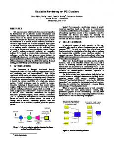
example, the as-built geometric data related to a cast-in-place column presented in Figure 1 was collected in multiple scans and aligned to form a single as-built model of the column. Each scan is given a different color in this figure in order to demonstrate that the data is collected from multiple sources or locations. Figure 1: Alignment of point clouds from several laser scans
This integration of data results in larger amounts of data that need to be visualized and manipulated. For example, the process of integrating the data collected from different laser scanner locations, called registration, has an additive effect on the file size. The high levels of detail in the data acquired through advanced reality capture technologies motivate development of design models with a similar amount of detail in order to support comparison of as-built and as-designed conditions. As a result of this detail, even small segments of construction site design models become significantly large. Data obtained using laser scanners can be overlaid with design data to visually detect deviations. For example, since we have gathered data about anchor bolts on construction sites using laser scanners (Gordon and Akinci 2005), we tried to include bolts in design models for comparison. The file size resulting from creating a 3D design model of a 10,000 square foot facility at this level of detail is 720 MB, while the file size without the bolts is 5 MB. Some visualization software tools, which we have assessed using as-built data, have difficulty with file sizes on this order of magnitude. We experienced long processing times, instability, or inability to load, manipulate, and analyze data using many of the software packages. This issue is compounded when these design files are overlaid with as-built data. Based on the difficulty in interacting with large 3D data sets, we anticipate that the problems will be compounded if available visualization software begins to support 4D visualization of as-built data as well. Given the large, detailed, spatio-temporal data needs to be analyzed for inspection, visualization software needs to incorporate hierarchical representations of data and strategies to load, display, manipulate, and render views of as-built models at different levels of detail.
5
VARIABLE DATA DENSITY Many of the software packages that we tested, such as the software originating from the manufactured parts domain, are designed for closed objects (i.e., the sensor is outside the scene) with fairly uniform density of data. By contrast, the objects that are scanned on construction sites are open objects (i.e., the scanner locations are within the scene) and the density of point cloud data collected on construction sites tends to be extremely variable, with large spaces between targets. Unless designed specifically according to this issue, some visualization software systems have difficulty with operations on this type of data, such as creating meshes in low density regions of variable density data. This challenges, and sometimes thwarted, the process of registering a mesh and a point cloud directly. Visualization software for the data gathered on construction sites needs to be able to provide mesh-generation capabilities that can accommodate variable-density data. ACCURACY AND ERROR In a data collection and analysis process, there can be errors associated with the sensors used, the data processing algorithm utilized and the corresponding errors with analysis. Given that these errors can accumulate and that the data needs to be analyzed based on stringent tolerances stated in construction specifications, it is necessary that errors be quantified and tracked throughout the process and reported to user who is visually analyzing the data. For laser scanners, sensor error increases with distance between the scanner and the target. Therefore, to determine the accuracy of the points, it is necessary to store or infer the pose and the distance of the scanner to the corresponding data set. Ideally, the uncertainty due to sensor error should be used in subsequent processing steps. For example, during registration, data with high uncertainty should have a reduced effect on the registration result. Similarly, low quality data should be given less importance in registration algorithms or they should be eliminated entirely prior to analysis. For example, if the same region of the site has been scanned from a long distance and from up close, only the data from the closer scan should be used for analysis in this region. None of the software packages we evaluated had the capability to explicitly model and utilize sensor error. Data processing for an as-built model generated using laser scanners consists primarily of registering (i.e., aligning) all the scans in the same coordinate system as the as-designed model. Normally, all scans are first registered with one another, and the resulting as-built model is registered with the as-designed model. The process typically involves two stages: pairwise registration and multi-view registration (sometimes called global registration). With pairwise registration, scans are registered to an initial scan one at a time, gradually building up a complete as-built model. Registering scans in a sequence can lead to a gradual accumulation of error. Multi-view registration simultaneously registers all scans, minimizing the overall registration error by distributing it across all scans in a principled manner. If a registration algorithm is working properly, the error will converge to a local minimum; however, the algorithms in some of the software packages we tested actually diverged, which resulted in low-quality as-built models. Some of the software tools characterized the amount of error introduced during registration, which assisted in tracking
6
how well the scans were aligned. In most cases, though, the registration error was not stored once the scans were absorbed into a single model. Error during analysis of the data formed the third important source of error. In order to perform inspections using the data collected on site, we need to make geometric measurements within the design data, geometric measurements within the as-built data, and geometric measurements among design and as-built data. Geometric measurements require geometric features to be identified to serve as a reference for the measurement that is to be performed. For example, length, distance, or angle measurements require geometric features like lines or surfaces or intersections of these features to be identified. Measurements within the design data can be performed in all of the tested software packages without any information loss. Features within the design can be identified accurately, and measurements, as a result, do not accumulate error. However, the software packages perform differently when measurements are made within the point clouds representing the as-built information or between point clouds and the design. In these cases, features must be identified in the point clouds first, to identify the reference points from which the measurements are to be made. In some cases, the software packages automatically identify features, such as lines and surfaces; however, the performance of these automatic feature identification tools differs from case to case. Repeated use of the automatic identification algorithms for a certain feature produces varying results. When a feature is identified, the software packages do not characterize the expected accuracy of the feature identification. This is needed to determine whether a deviation identified in the as-built model might be violating a specification. When automatic feature identification is not possible, features must be identified manually. Figure 2, for example, shows the manual measurement of the cross-sectional dimensions of a column made by fitting planes to a set of points and measuring the perpendicular distance between these planes. This process requires that the user identify features within the point cloud data. For a line feature, for example, the start and end point of that feature need to be determined within the point cloud. This is often difficult because the laser points are not aimed at the feature explicitly, but measure points within the immediate proximity of the built line feature. This leads to an approximate representation of the feature, which makes it difficult for the user to select the correct points for defining the features. Once a feature is defined, there is no notion of expected error for that feature. Figure 2: Measurement of the cross-sectional dimensions of a column
7
Construction sites are very large in comparison to the tolerances that exist for elements on site. Consequently, it is a challenge to develop complete as-built models while maintaining high accuracy within the data. It is desirable to track the amount of error introduced at subsequent stages of data collection, processing, and analysis in order to help integrate the data into a complete as-built model and to determine how accurate the data truly is in support of downstream analysis. 4D VISUALIZATION Storing and reasoning with temporal data assist inspectors in interacting with as-built data. Since there are numerous components arriving or being installed on site - each on time, early or late according to a construction schedule - a 4D environment is a useful interface to view reality capture data in comparison with design data. Additionally, 4D views of as-built data can permit inspectors to follow the progression of a discrepancy, to determine if it is resolved and if it is worsening or propagating. Visualization of point cloud data has been attempted recently with commercially available 4D software with limited success (Shih 2004). The visualization software tools designed for LADAR data do not support 4D views of as-built data. Rather, these tools come closest to 4D visualization with file overlay features. PRESENTATION OF META-DATA Additional data, such as sensor locations, sensor error and other meta-data associated with the data collected on site, can be used to augment data used for inspection tasks. Embedded sensors are not always visible within data captured using area scanning technologies. However, their presence or absence is helpful to record. Meta-data about sensors embedded within building elements can be used to help identify the location and orientation of a sensor. Exact location information may not be available, so it is necessary to develop a means of distinguishing whether the sensor location is in exact or approximate coordinates. Status information, such as whether a sensor is recording, inactive, not responding, can be used to determine whether it is possible to query the sensor for additional details about a component. In order to gain confidence in data, sensor characteristics, such as sensor accuracy, calibration history, sensor type, ID, and manufacturer, can assist an inspector in interpreting the sensor data. We did not find a capability to store meta-data or to cross-reference unlike data sets (such as data from LADAR and embedded sensors) in any available visualization technologies. CONCLUSIONS The rise in interest in applications of reality capture technologies, such as LADAR and embedded sensing, motivates the assessment of commercially available visualization tools to support the data collected over time and space to support construction inspection tasks. While available visualization technologies deliver many of the functionalities needed to support inspection (such as registration, manipulation, analysis, 4D visualization, inspection support, deviation detection, and reporting), there is still some need for improvement in addressing the functional issues associated with the size, accuracy, and heterogeneousness of data to support inspection tasks. Furthermore, in certain cases, the performance of the technologies
8
needs to be improved to support visualization and analyses of large, detailed as-built and asdesigned models. Although the tools we evaluated provided modeling, presentation, and analysis functionalities that make model-based inspections technologically feasible, they are challenged by several characteristics particular to construction inspection applications. The size, detail, and variable density of construction site as-built models challenge the performance of the tools, suggesting the need for the development of different strategies for development of and interaction with as-built models. Error is introduced silently throughout the collection, processing, and analysis of data, and should be recorded and presented to the user. While geometric data conveys useful information to inspectors, physical data such as component strength, is also essential to inspect. Consequently, integration of data obtained from embedded sensors can provide significant visibility of as-built conditions. Finally, meta-data, such as temporal data, sensor location, and sensor error can augment visualization of the data gathered on site. ACKNOWLEDGEMENTS The project is funded by a grant from the National Science Foundation, CMS #0121549. NSF's support is gratefully acknowledged. Any opinions, findings, conclusions or recommendations presented in this paper are those of authors and do not necessarily reflect the views of the National Science Foundation. Findings and conclusions in this paper are made in collaboration with the research team listed on www.ce.cmu.edu/~itr/. REFERENCES Akinci B., Garrett, J., Patton, M. (2002) “A Vision for Active Project Control using Advanced Sensors and Integrated Project Models.” Specialty Conf. on Fully Integrated and Automated Project Processes, Va. Tech, Jan., 2002, ASCE, 386-397. ACI (1990) “Standard Specifications for Tolerances for Concrete Construction and Materials (ACI 117-90).” American Concrete Institute, Reported By ACI Committee 117, 1990. Gordon, C. and Akinci, B. (2005). “Technology and Process Assessment of Using LADAR and Embedded Sensing for Construction Quality Control.” Construction Research Congress 2005, San Diego, CA, April 5-7, 2005. Shih, N., Wu, M., and Kunz, J. (2004). “The Inspections of As-built Construction Records by 3D Point Clouds.” CIFE Working Paper #090, Aug. 2004.
9