traditional laboratory experiences, the distributed lab is brought home by each ... or teaching assistants for maintenance and repair, and have no training or ...
Session 1526
At-Home System and Controls Laboratories William Durfee, Perry Li, David Waletzko Department of Mechanical Engineering, University of Minnesota
Abstract We are piloting the concept of distributed laboratories in the form of kits that students take home and work on much like a problem set. The kits have an embedded microcontroller and communicate to the student’s home PC over a serial port. The home PC provides the needed computational horsepower for experiment control, data collection, data analysis and reporting. The microcontroller handles real-time control tasks. Two kits have been developed, a fourthorder, linear mass-spring-damper system for frequency response and system identification, and an analog filtering system that uses music and synthetic sound as an input. Based on the experiences with and evaluation of the first generation modules, an improved second generation module that adds PID control is under development. Introduction For engineering students in introductory system dynamics and controls courses who need to gain intuitive feel for physical systems, the distributed laboratory is a way to explore basic concepts through a hands-on experience that uses inexpensive, computer-controlled hardware kits. Unlike traditional laboratory experiences, the distributed lab is brought home by each student and tackled on a self-paced schedule in much the same manner as a homework assignment, thus allowing the student to customize the laboratory experience to his or her learning style. The intent of this project is to pilot an innovative approach to system dynamics and control laboratories that incorporates proven hands-on learning principles to improve student learning. The long term goals are to create program-wide distributed labs using modular hardware and software components that students take home to do labs in their dorm room. The specific objective of this project is to pilot a distributed lab for system dynamics and control to understand the strengths and weaknesses of the concept. Lab kits whose parts cost less than $100 when purchased in lot sizes of 100 have been designed and tested in a pilot project. The kits contain a controller board based on a standard microcontroller chip that implements real-time control and data acquisition software and communicates with a host over a serial port. The systems under study are hardware modules that connect to the controller board. The host computer is the student's home PC running a Visual Basic application for experiment control. Effective laboratories reinforce theoretical principles learned in lecture, textbooks and assignments by enabling the student to experience and manipulate system responses first hand.1 ABET accreditation requires that graduates have “an ability to design and conduct experiments as well as to analyze and interpret data.2” System dynamics and control is a core engineering topic and it is important that students graduate with a grounding in how real physical systems behave.3-6 Traditional, centralized laboratories have limitations. On the programmatic side, labs
require physical space, always at a premium in a university. Labs must be staffed by faculty or teaching assistants which is costly. Because traditional labs typically use high-performance computers and sophisticated plants to control, the number of lab stations is generally less than the number of students which means students work in groups. Lab hours are limited. When your scheduled two hours are up, you have to leave. Once in the lab, students cannot break the rules and try something with the equipment that is off task because the helpful lab assistant is always looking over their shoulder. Virtual labs use computer-based simulations to emulate hardware. The advantages of a virtual lab are they eliminate the need for lab space, require no instrumentation, do not need technicians or teaching assistants for maintenance and repair, and have no training or safety issues. Virtual lab equipment cannot break so students can try many different designs without fear of damaging the hardware. Virtual labs can be web-based or the software distributed to students for operation any place and any time. On the other hand, virtual labs are not real hardware, they match theory exactly (because the simulation equations are derived from the theory), and they work perfectly every time; all of which can lead to misconceptions in how the real world works. A compromise is web access to real laboratory equipment, in much the same manner that astronomers remotely control high end space imagers for research.7-10 Remote, web-based control means students can perform the lab from any place and at any time. Often, web-cam access is included so that the student can see the experiment. The controller generally has built-in safety limits to prevent the student from setting conditions that could damage the hardware. Like the telescope, this means expensive systems, including those that require clean room environments, can be implemented. With large classes, scheduling returns as a main issue. Distributed labs are a novel approach to giving students hands-on experience. Rather than relying on a central facility that students come to at a specified hour with fixed supervision, students can take the lab home to explore on their own terms in as much or little detail as they wish. Recent advances in integrated microcontrollers and sensing components, coupled with careful mechanical design make it possible to replicate hardware for each student at a parts cost of under $100 per unit. Almost all students have powerful home computers that can be harnessed for supervisory control and data analysis. For the first time, laboratories can be treated as homework assignments that are done entirely at home just like a problem set. For this project, we focused on introductory system dynamics and control. This core engineering topic rests on a rigorous mathematical foundation that causes many students to miss gaining a physical intuition of basic concepts because they become enmeshed in the equations. Principles such as time and frequency response, resonance, poles and zeros, stability and controller performance lie at the core of system dynamics and control, but can be abstract and obtuse for first-time students. A laboratory experience is essential for students of system dynamics and control. The major design requirements for the take home kits were: 1. Demonstrates fundamental principles (for high learning impact) 2. Rugged (to survive trips back and forth to school in a backpack) 3. Small (about the size of a large textbook for portability and storage) Proceedings of the 2005 American Society for Engineering Education Annual Conference & Exposition Copyright © 2005, American Society for Engineering Education
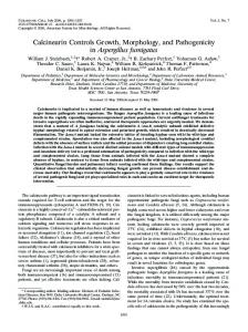
4. Simple (operation is easily understood) 5. Inexpensive (under $100 in parts cost per unit in lots of 100 units) 6. Easily manufactured by unskilled labor (for in-house assembly) Apparatus The lab kit modules have three parts (Fig. 1). First is the host PC running supervisory software written in Visual Basic and talking to the control board through its serial port. The PC is used for setting experiment parameters, viewing results through plots, and other supervisory tasks. The host software is easily maintained through updates, downloadable by the student. We make the assumption that students own or have ready access to a PC running Windows. From recent surveys, over 90% of students in Mechanical Engineering own a Windows PC, a number we expect will approach 100% in the next few years. School computers are available for those who do not own.
Motor driver PIC 16F 873A micro
Host PC running Visual Basic
Motor
Serial Sensor interface
System Power supply
Sensors
Controller board
Figure. 1. Diagram of module architecture. The PC controls the experiment and collects data. The controller board reads sensors and drives actuators.
Second is the controller board, a custom 2-sided printed circuit board containing a PIC16C873A microcontroller clocked at 4 MHz that performs all real-time control tasks. The microcontroller has an on-board, 10-bit analog-to-digital converter for reading analog sensors and PWM output for driving a small DC motor. The board is powered by a 12 VDC, 0.5 A wall plug power supply that also provides power to sensors and motor. Third is the dynamic system that the student tests, controls and observes. Sensors measure system output and are used by the real-time controller and sent upstream to the PC for display, plotting and analysis. The dynamic system can be integrated onto the control board or be a separate unit the plugs into the control board. Two lab kit modules were designed. One module is a fourth-order mass spring damper (MSD) system that approximates a quarter-car suspension. The other is an analog filtering (AF) system Proceedings of the 2005 American Society for Engineering Education Annual Conference & Exposition Copyright © 2005, American Society for Engineering Education
where passive resistor and capacitor networks are constructed by students and applied to music and other sound sources from the PC to hear and analyze the effects of first order high and low pass filters. The MSD system teaches principles of time and frequency response, resonant systems, and the effect of parameter changes on a system. It is implemented as a vertical stack of masses and springs configured in a classic quarter car model with a lower mass connected to the driving input through a spring and the sprung mass connected to the lower mass through a parallel spring and damper (Fig. 2). The lower spring is tied through a linkage to a small gear motor to provide a variable speed sinusoidal input. All components slide up and down on a post. Friction damping is implemented by a rubber band squeezing a foam ring against the shaft. Parameters are changed by replacing springs and masses from a collection included with the kit. Removing the top mass and spring reduces the system to a second order model. Ring magnets are fastened to the masses with matching Hall effect sensors on the control board to measure mass positions. An optical sensor on the drive link is used for motor speed control. The system was designed to minimize parts cost and assembly time. For example, all components, including the motor and sensors, attach directly to the circuit board to eliminate most wiring and connectors. The circuit board is also the main vertical structural support to position the sensors near the masses.
Figure. 2. Fourth order mass-spring-damper system.
The host program on the PC displays a real-time graph of the mass positions (Fig. 3). Students can specify a particular drive frequency and record position output amplitude to develop measurement based Bode magnitude and phase plots. Releasing the system from an initial condition provides a step response. Effects of damping on resonance for second and fourth order systems are studied by using a tighter rubber band on the foam. Other simple experiments are used to measure or identify values of springs, masses and damper. The electronics board for the MSD module contains the PIC microcontroller, motor driver, sensor conditioning circuits, and serial level converter for communication with the PC. (Fig. 4)
Proceedings of the 2005 American Society for Engineering Education Annual Conference & Exposition Copyright © 2005, American Society for Engineering Education
Figure. 3. Screen shot of MSD system control program on PC.
Figure. 4. Schematic for MSD controller board..
Proceedings of the 2005 American Society for Engineering Education Annual Conference & Exposition Copyright © 2005, American Society for Engineering Education
The analog filtering module teaches principles of first order high and low pass networks. Using an audio circuit allows students to hear the effect of the filters they build on their favorite music or on combinations of sine waves. The module is constructed on a single circuit board that connects to the PC sound card line in and line out ports (Fig. 5). Sound files or real-time sine waves are sent to the board via the sound card. A small breadboard on the module provides a platform for constructing first or higher order passive filter networks from a kit of discrete resistors and capacitors. The student plugs headphones or powered speakers into the audio output jack and select a switch to hear either the filtered or unfiltered sound wave. The board has an onboard headphone amplifier with volume control. The filtered and unfiltered signals are sent back to the PC via left and right channels of the line in port on the sound card.
Figure. 5. Analog filter system.
The host program displays real-time wave forms of the filtered and unfiltered signals, or a realtime spectrogram of the signals (Fig. 6). The student can pick any .wav or .mp3 music file to send to the module, or a single sine wave or sum of two sine waves at any set of frequencies. Single sine wave input can be used to construct experimental Bode plots. The electronics board for the analog filtering module has an op-amp variable gain stage and a single chip headphone amplifier (Fig. 7).
Proceedings of the 2005 American Society for Engineering Education Annual Conference & Exposition Copyright © 2005, American Society for Engineering Education
Fig.6. Screen shot of analog filter system control program on PC.
Fig.7. Schematic for analog filter board..
Proceedings of the 2005 American Society for Engineering Education Annual Conference & Exposition Copyright © 2005, American Society for Engineering Education
Results Thirty of each module were constructed and distributed to students in the core system dynamics and control course (Fig. 8).
Figure 8. MSD (left) and analog filtering (right) modules ready for distribution.
The students receiving the modules were chosen randomly out of the 67 students in the course and completed a lab assignment at home in lieu of two problems on each of two problem sets. The kits were also distributed during a smaller summer semester section of the course. Based on a post-use survey, students reported that the kits helped them to understand concepts of filtering and bode plots, and in general thought the system and software was easy to set up and easy to use. After being exposed to the lab assignments, scores improved on a short quiz designed to evaluate basic knowledge of bode plot and filtering concepts compared to scores on the same quiz applied before lab exposure. Students wrote that the biggest strengths of the lab kits were the ability to get a hands on learning experience that promoted a better understanding of the concepts, that the kits went beyond the pictures and problem sets in the book, that using sounds and music was a good way to understand filters, and that the kits and software were easy to set up and easy to use. Students wrote that the biggest weaknesses of the lab kits were the lack of a detailed lab manual, and that the software was difficult to install on some computers. While the authors concur that the pilot lab kits were a success, the pilot project revealed several weaknesses that must be addressed in the next generation of devices. First, the design must be rigorously optimized for efficient manufacturing. While the parts cost was reasonable, assembly time was not. Second, the linear motion of the MSD system must be changed to rotary motion. Low-friction linear travel cannot be achieved simply and inexpensively. Also, the fourth-order system was beyond the academic level of beginning students. Second-order is sufficient to understand the basic principles of frequency response. Third, the analog filtering module cannot count on all PCs having a line input jack and must use the mono mic jack instead. Fourth, the Proceedings of the 2005 American Society for Engineering Education Annual Conference & Exposition Copyright © 2005, American Society for Engineering Education
level of software installation support was excessive and will not scale up to larger number of students. The software must run on many flavors of Windows operating system, must be transparent to install, must come with easy to understand setup instructions, and must not require manual changing of settings on the PC. Many additional, but minor changes were identified. A revised module is under development. It will combine analog filtering and a second-order rotary spring-mass-damper system onto a single board to reduce cost. Closed-loop control capability will be added. Acknowledgement This project is supported by the National Science Foundation under the Course, Curriculum & Laboratory Improvement Program of the Division of Undergraduate Education, Grant # DUE0231121.
References 1. NSF (1992), America's Academic Future, JR Lohmann and AM Stacy Eds, National Science Foundation Report NSF91150, Jan. 1, 1992. 2.
ABET (2002), 2002-2003 Criteria for Accrediting Engineering Programs, ABET, Baltimore. (Available on-line at www.abet.org/)
3.
P Antsaklis et al (1999), Report on the NSF/CSS workshop on new directions in control engineering education, IEEE Cont Sys Mag, 19(5):53-58.
4.
DS Bernstein (2001), Enhancing undergraduate control education, IEEE Cont Sys Mag, 19(5):40-43.
5.
DS Bernstein (2001), A plant taxonomy for designing control experiments, IEEE Cont Sys Mag, 21(3):7-14.
6.
R van de Molengraft, M Steinbuch, B de Kraker (2005), Integrating experimentation into control courses. IEEE Cont Sys Mag, 25(1):40-44.
7.
M Hites, M Sekerak, L Sanders (1999), Implementing and evaluating web-based "hands-on" laboratories for undergraduate education, Proceedings of the ASEE IL/IN Sectional Conference, March 1999.
8.
CC Ko, BM Chen, J Chen, Y Zhang, KC Tan (2001), Development of a web-based laboratory for control experiments on a coupled tank apparatus, IEEE Trans Ed, 44(1):76-86.
9.
A Valera, JL Diez, M Valles, P Albertos (2005), Virtual and remote control laboratory development. IEEE Cont Sys Mag, 25(1):35-39.
10. M Casini, D Prattichizzo, A Vicino (2005), A student control competition through a remote robotics lab. IEEE Cont Sys Mag, 25(1):56-59.
Author Biographies WILLIAM DURFEE is Professor and Director of Design Education in the Department of Mechanical Engineering at the University of Minnesota, Minneapolis MN. He received his A.B. degree in Engineering and Applied Physics from Harvard University and his M.S. and Ph.D. degrees in Mechanical Engineering from the Massachusetts Institute of Technology. His interests are rehabilitation engineering, medical device design, and design education.
Proceedings of the 2005 American Society for Engineering Education Annual Conference & Exposition Copyright © 2005, American Society for Engineering Education
PERRY LI is Associate Professor of Mechanical Engineering at the University of Minnesota. He received his B.A. degree in Electrical and Information Sciences from Cambridge University, his M.S. degree in Biomedical Engineering from Boston University, and his Ph.D. in Mechanical Engineering from Berkeley. His interests are fluid power, control of printing and imaging systems, paper manufacturing, robotics, and intelligent control. DAVID WALETZKO is pursuing his M..S degree in the Department of Mechanical Engineering at the University of Minnesota. He received his B.S. degree in Mechanical Engineering from the University of Minnesota. His interests are design, mechatronics and real-time control.
Proceedings of the 2005 American Society for Engineering Education Annual Conference & Exposition Copyright © 2005, American Society for Engineering Education