Also the post processing stage improved the fidelity level of reconstructed audio signal. Index TermsâAudio compression, Discrete Cosine. Transform, Scalar ...
ISSN: 2277-3754 ISO 9001:2008 Certified International Journal of Engineering and Innovative Technology (IJEIT) Volume 4, Issue 1, July 2014
Audio Compression Based on Discrete Cosine Transform, Run Length and High Order Shift Encoding Zainab T. DRWEESH, Loay E.GEORGE efficient joint implementation of DCT, as a method to obtain a sparse audio signal representation, and the application of the compressive sampling algorithm to this sparse signal [6]. Harmanpreet Kaur and Ramanpreet Kaur proposed a speech compression method using different transform techniques. The signal is compressed by DWT technique afterward this compressed signal is again compressed by DCT and then this compressed signal is decompressed using DWT technique. Harmanpreet, K., Ramanpreet have investigated the use of DWT & DCT as analysis tools for speech signal coding, they used Peak Signal to Noise Ratio and Normalized Root Mean Square Error (NRMSE) to evaluate the effectiveness of different filters of wavelet family [7]. Patil and et al proposed a simple discrete wavelet transform & DCT based audio compression scheme. It was implemented using MATLAB, the experimental results indicated that in general there is improvement in compression factor and signal to noise ratio with DWT based technique [8]. In this paper we introduce a simple DCT transform based coding system to decompose audio signal. DCT is adopted because of its nice de-correlation and energy compaction properties. The resulting transform coefficients are quantized using non uniform scalar quantization. Then, the quantized values are represented using run length encoding (RLE) to prune the long 0's runs, followed by an improved shift coding algorithm.
Abstract— Audio compression addresses the problem of reducing the amount of data required to represent digital audio. It is used for reducing the redundancy by avoiding the unnecessary duplicate data. In the present work a low complexity and efficient coding scheme based on discrete cosine transform (DCT) is proposed. The proposed system consists of audio normalization, followed by DCT transform, scalar quantization, improved run length encoding and a new high order shift coding. To reduce the effect of quantization noise, which is notable at the low energetic audio segments, a post processing filtering stage is introduced as the final stage of decoding process. The system performance is tested using different audio test samples; the test samples have different size and different in audio signal characteristics. The compression performance is evaluated using peak signal to noise (PSNR) ratio and compression ratio (CR). The test results indicated that the compression performance of the system is promising. The compression ratio is increased with the increase of block size. Also the post processing stage improved the fidelity level of reconstructed audio signal. Index Terms—Audio compression, Discrete Transform, Scalar Quantization, Lossless Coding.
Cosine
I. INTRODUCTION The growth of the computer industry has invariably led to the demand for quality audio data. Compared to most digital data types, the data rates associated with uncompressed digital audio are substantial. For example, if we want send high-quality uncompressed audio data over a modem, it would take each second’s worth of audio about 30 seconds to transmit. This means that the data would be gradually received, stored away and the resulting file played at the correct rate to hear the sound. However, if real-time audio is to be sent over a modem link, data compression is needed. Compression can be considered as a key that reduces the amount of data used to convey the same information [1, 2]. The most popular audio coders are based on using two techniques (i.e., sub-band coding and transform coding). Sub-band coding splits signal into a number of sub-bands, using band-pass filter [3]. Transform coding uses a mathematical transformation like FFT and DCT. Jacaba discussed the application of the modified discrete cosine transform (MDCT) to audio compression, specifically the MP3 standard. MDCT plays a very important role in perceptual audio coding [4]. Wang and Vilermo compared the use of Modified Discrete Cosine Transform (MDCT) in audio coding and error concealment with the perspective Fourier frequency analysis [5]. Alvarado and Garcia proposed an
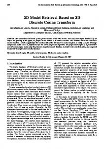
II. AUDIO COMPRESSION SYSTEM The most common characteristic of audio signals is the existence of redundant information lay between the adjacent samples. Compression tries to remove this redundancy and make the data de-correlated. Typical audio compression system contains three basic modules to accomplish audio compression. First, an appropriate transform is applied. Second, the produced transform coefficients are quantized to reduce the redundant information; here, the quantized data hold errors but should be insignificant. Third, the quantized values are coded using packed codes; this encoding stage changes the format of quantized coefficients values using one of the suitable variable length coding technique. Figure (1) shows the layout of the proposed system, the modules of our proposed system are described in the following sections. A. Discrete Cosine Transform (DCT) This transform had been originated by [Ahmed et al. 74]. Since that time it was studied extensively and commonly used in many applications [9]. At present, DCT is widely used transforms in image and video compression algorithms. Its
45
ISSN: 2277-3754 ISO 9001:2008 Certified International Journal of Engineering and Innovative Technology (IJEIT) Volume 4, Issue 1, July 2014 popularity is due mainly to the fact that it achieves a good data All other transform coefficients are called the AC compaction; because it concentrates the information content coefficients [6]. in a relatively few transform coefficients [10]. Its basic B. Quantization operation is to take the input audio data and transforms it from Quantization is an important stage for data compression, it one type of representation to another, in our case the signal is a block of audio samples. The concept of this transformation makes approximate mapping of transform coefficient values is to transform a set of points from the spatial domain into an to integer values have finite length of binary representation identical representation in frequency domain. It identifies [11]. Any quantization method should be based on a principle pieces of information that can be effectively thrown away that determines what data items to quantize and by how much [9]. In transform based coding scheme, the lossy encoder must without seriously reducing the audio's quality. quantize each frequency component. If the encoder allocates more bits to each frequency, less error (noise) is introduced, but more space is required to store the result. Conversely, fewer bits allocated to each frequency results in more noise, but less space is required to store the result [12]. C. Entropy Encoding Entropy encoding is used to further compresses the quantized values losslessly to give better overall compression. Different encoding methods can be used (e.g. Huffman, Run Length, Arithmetic, LZW, and Shift Coding). Statistical based encoding methods are used to remove data that are repetitively occurring. Some encoding methods can, also, reduce the number of coefficients by removing the redundant data. In our proposed system the run length encoding method is applied first to prune the long runs of quantized coefficients, then an improved progressive shift coding method is used to firstly prune the existing second order statistical redundancy and, lastly, to encode the produced coefficients individually using variable encoding that based on shift-key mechanism. D. Run Length Encoding (RLE) Run length encoding is the simplest form of redundancy removal. It removes redundancy by relying on the fact that any string of symbol may contain repeated sequences or “runs” of the same symbol. The runs of the same symbol are encoded using two entities: (i) a count suggesting the number of repeated symbols and (ii) the symbol itself [2].
Fig. 1: The Proposed System Layout
The mathematical representation for one-dimensional DCT is: (1) The forward 1D DCT equation is [9]:
E. Shift Coding Shift coding method is used to reduce the size (in-bits). In this method a list of code words is generated to encode the sequence of numbers. The lengths (in terms of bits) of code words representing the high redundant symbols are less than the length required to represent the maximum symbol value when it is coded using fixed length coding. The size (in bits) required to encode this sequence when using fixed length coding can be calculated as follows:
Where, f(0...N-1) is the discrete sequence of signal f; N is the number of f() elements, C(0...N-1) is the cosine transform coefficients, and
(2) The inverse 1D DCT equation is: Where, Max is the highest symbol value found in the input sequence, n is the number of elements, and is a function returns lowest integer value that higher or equal to the input argument. The performance of shift coding is better when the sequence of numbers has a histogram whose shape is highly peaked. The main advantage of shift coding is its required
The first transform coefficient C(0) is an indicator for the average value of the sample sequence; in the literature, this coefficient is called the DC coefficient of the signal. 46
ISSN: 2277-3754 ISO 9001:2008 Certified International Journal of Engineering and Innovative Technology (IJEIT) Volume 4, Issue 1, July 2014 overhead information is short. The disadvantages of the with the time; if DCT is applied once on the whole signal traditional shift coding method are: (i) it deals with each samples and doing the rest steps of the encoding unit then symbol value individually (i.e., use a code word to represent the encoding process outcome become less packed (i.e., each symbol, (ii) it spends more bits if the sequence histogram less compression gain is attained). The number of has long tails, this leads the encoder became less efficient. partitions is computed as follows: The consequences of these disadvantages appearing clearly when we using noisy wave file with 16 sample resolution. In order to handle the above encoder weakness, we have introduced additional steps to shift coding algorithm, such Where, Nblocks is the number of the partitions generated that the efficiency of this new encoder variant is more stable from original wave, WavSize is the number of samples of and robust. The introduced steps are the following: the loaded audio data, Sblock is the predefined size for each 1. Mapping symbol values to be always positive. partition (block), and LastBlockSize is the size of the last 2. Making the dynamic range of input symbols values partition of the original wave. bounded to be always lower than certain value. 4. Apply DCT (equation 1) on each audio block to produce 3. Detect the most redundant pairs of symbols and the set of transform coefficients C(). represent each pair by a single symbol. 5. Apply progressive scalar quantization to quantize the DCT 4. Apply a shift encoding optimizer to find the best lengths coefficients of each block. This step will reduce the of the short and long code words. number of bits needed to represent approximately the transform coefficients, and to prepare them to the entropy encoding step. The applied equations of quantization process are the following: a. For DC Coefficient:
After applying the above sequence of coding steps the traditional shift coding is applied on the produced sequence of symbols. Due to the above added steps the required overhead information is increased, but this increase is minor when compared with the length of the input sequence of generated symbols due to encoding audio data.
Where, C(0) is the DC-coefficient, Cq(0) is the quantized DC coefficient. b. For DC Coefficient:
III. PROPOSED SYSTEM WORKFLOW The introduced system consists of two major units; the first is the Encoding unit and the second one is the Decoding unit.
Where, Q1 is the quantization step value that used only to quantize the second DCT coefficient (i.e., 1st AC Coefficient) of each block. The coefficient index u takes the values (u=1, 2 …Sblock). The parameter β is the progressive rate of increase of the quantization step for the AC-coefficients. 6. In our proposed system, the run length encoding (RLE) step is used because of the redundant occurrence of many sequences consist of long runs of zeros. Shift coding could not efficiently handle these long runs because it prunes only the short runs by pairing step. RLE will represent the long repeated sequences of symbols as records each consist of (Run Value, Length). 7. Shift coding is applied after RLE, the stream coefficients are shift coded, usually the incoming stream, after the previous steps (i.e., DCT, quantization, and RLE), has highly peaked histogram which makes shift coding a good entropy coding based choice for further compression. The introduced enhanced shift coding consists of the following steps: a. Mapping to positive: Convert all samples of the stream to positive numbers; this step is useful to simply the next coding steps. The following mapping equation had been used to convert the signed samples into positive samples:
A. Encoding Unit This unit involves the following stages: 1. Loading the waveform audio file (with WAVE) format. This process includes reading the header data to get the basic file and signal specification information (i.e., number of samples, number of channels, sampling rate, and sampling resolution). Then the audio signal data is loaded as an array of unsigned bytes when the sample resolution is (8 bit/sample) and as an array of signed integers if the sample resolution is 16 bit/sample. 2. Normalizing the loaded audio data values to the range [-1,1] using the following equations: a. For 8 bit sampling resolution:
b. For 16 bit sampling resolution:
Where, W(i) is the ith element value of the loaded audio data. 3. Partition the array of data into a number of non-overlapping blocks with same size, except the last partition which may be of smaller size. Signal partitioning into blocks is necessary because the characteristics of the sound changes
47
ISSN: 2277-3754 ISO 9001:2008 Certified
b.
c.
d.
e.
f.
International Journal of Engineering and Innovative Technology (IJEIT) Volume 4, Issue 1, July 2014 g. Apply shift coding optimizer to find the optimal two code word sizes needed to represent the small and large th sequence elements values. The applied optimization Where, C(i) the i element value of the quantized criteria is: signed samples value. Determine the optimal range value whose length is less than the highest value found in input sequence. The following equations have been applied to calculate the The optimizer should find the best values for b1 & b2 leads to optimal range value: lowest possible value of T. The values of b1 & b2 represent the length of short code words and long code words, respectively. The range of b1 and b2 lay within the range [1, ]. The array His() represent the histogram array. The symbol R is equal to 2b1-2, which represent the highest value of the short codeword. h. Do the traditional shift coding operation, and then save the output code words into the binary output file. B. Decoding Unit The decoding unit consists of the inverse operations to those applied in the encoding process; also these operations Where, P is the optimal range value, Max is the highest are applied in reverse order. The operations are: (i) shift sequence elements value, Alpha is a user defined value decoding, (ii) long runs expansion, (iii) de-quantization, (iv) (in this work its value set 2), Mean is the mean value of inverse DCT, (v) mapping to the byte range [0,255] in case of the sequence elements, MAD is the corresponding 8-bit sample resolution, and to the integer range [-32768, Mean Absolute Deviation, S() is the sequence array, 32767] in case of 16-bit sample resolution. In our proposed LenM is number of the coefficients. system a post processing stage is added as last stage of the Do range clipping by scanning the sequence elements, decoding module. This stage is a selective based low pass during this scanning any element has a value larger or filter used to reduce the subjective effect of the produced equal to P it is coded using a set consist of three noise whose effect is sensible at the sound segments have low numbers (P, S1, S2), their values are determine by using power. Also, the conducted tests indicated that the error level the following equations: due to lossy compression is reduced when the proposed post-processing is applied. The proposed low pass filter could describe mathematicBefore starting the pairing process, set the value of ally as follows: Pp=P, this parameter is used to count the dynamic range after applying the Pairing stage. Do pairing step by finding the most redundant pair and replace it by single value (Pp+1); this step should Where, repeated for a number of times (use the stopping condition: if the reduction ratio of sequence length after the pairing stage is less than 0.01 then stop the pairing Or process; otherwise repeat the process). The pair replacement step is as follows: Let (OptL1, OptL2) are the elements of the highest redundant pair, then replace the pairs (OptL1, OptL2) found in the sequence by a Where symbol value (P+1). After each pairing round /6 (21) increment Pp by 1. Establish the histogram of the produced sequence after IV. TEST RESULT pairing stage, then establish the necessary index table This section is dedicated to present the results of the tests for inserting the histogram values of the new symbols conducted to investigate the effects of some involved coding elements (whose values lay within the range [P, Pp]) parameters on the performance of the proposed DCT based added in the pairing stage within the histogram audio coding schema. The performance of any lossy audio sequence whose index is [0, P]. Use this index table to compression method is defined in terms of compression gain change the elements values lay within [P+1,Pp] by (either compression ratio, CR, or bitrate, BR) and fidelity index values, and all values of the histogram elements [0,P] are shifted up properly to host newly indexed criteria (either root mean square error or PSNR) [9]: symbols. 48
ISSN: 2277-3754 ISO 9001:2008 Certified International Journal of Engineering and Innovative Technology (IJEIT) Volume 4, Issue 1, July 2014
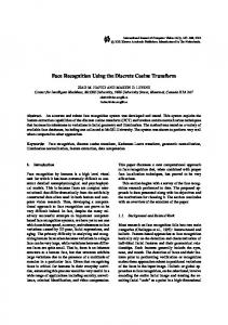
Where, x(i) is the ith element value of the original audio data, y(i) is the value of the reconstructed audio file, n is the number of the audio samples, and R is the dynamic range of audio samples values (i.e., for 8-bits sample resolution R=255, and for 16-bits sample resolution R=65535. In our work, a set of tests was conducted to evaluate the performance of the proposed system. The importance of our work lies in the possibility of making good reduction in audio data size while the audio quality remains above the acceptable. Several parameters were taken into consideration to study the performance of the suggested audio compression system. The proposed audio system was implemented using C## programming language, also all additional programs for testing purpose have been developed using same programming language. The effects of the following control parameters have been investigated: (i) quantization step (Q0) for DC coefficient, (ii) initial quantization step (Q1) for AC coefficient, (iii) progressive rate parameter (β), (iv) block size (Sblock), (v) sampling rate, (vi) sampling resolution, and (vii) post filtering. Table (1) shows the characteristics of the audio file, which was used in the tests. Figure (2) present the waveform patterns of these samples. As performance indicators the compression ratio (CR), and PSNR have been calculated. Table (2) presents the adopted default values of the considered control parameters, these values are selected after making a comprehensive tests and choosing the best setup of parameters. The effects of each parameter are explored by varying its value while setting other parameters fixed at their default values.
Fig. 2: The Waveform of the Tested Waveform Files Table 2: The Default Values of the Control Parameters Parameter Sblock
Default Value 36 Sample
Sampling Rate
30 KHz
Sample Resolution Q0 Q1 Β
Range Range=[20, 40] {44100, 30000, 22050, 11025}
8 bps
{8, 16}
0.02 0.077 0.43
[0.02, 0.026] [0.045, 0.081] [0.08, 1.03]
Figure (3) presents the effects of Q0 on PSNR and compression ratio. While, figure (4) shows the effects of Q 1, and figure (5) presents the effects of (β) parameter. It is obvious that the increase of these parameters causes increase in the attained compression gain while decrease the fidelity level.
Table 1: The Attributes of the Audio Test Samples Audio Samples
Attribute Test1.Wav
Test2.Wav
Test3.Wav
Sampling Rate (KHz)
32
44.1
44.1
Sample Resolution (bps)
8
8
16
Size (KB)
848
447
893
Audio Type
Soft Music
Song
Animal Voice Fig. 3: The Effects of Q0 (the audio sample is Test1.wav)
49
ISSN: 2277-3754 ISO 9001:2008 Certified International Journal of Engineering and Innovative Technology (IJEIT) Volume 4, Issue 1, July 2014 Figure (7) shows the effect of sampling rate on compression performance (for the two case of block size 20 & 40). The results indicate that the effect of sampling rate on the compression performance is reversed when the block size becomes high. For small block size the sampling rate doesn’t show significant effect on the compression relationship, but at large block size the compression gain is higher at large sampling rate. In this test the test samples "Test2.wav" and the "Test3.wav" are down sampled by (2) twice times to get the audio wave form at sampling rate (11025 KHz).
Fig. 4: The Effects of Q1 (the audio sample is Test1.wav)
Fig. 7: The Effect of Sampling Rate on the Compression Performance (the audio sample is Test2.wav)
Figure (8) shows the effect of sampling resolution on performance of our compression schema. The results refer that the impact of sampling resolution is significant; the 16 bit sampling resolution gives more impressive result. In this set of test a conversion from 16-bits (2's complement integer representation) to 8-bit (unsigned byte representation) is done to get the corresponding low resolution audio sample. Figure (9) presents the effects of block size on the encoding time; as long as the block size is increased the encoding time is increased. So, a trade off should be taken into consideration for choosing the suitable block size when both high compression ratio low fidelity level and low encoding time.
Fig. 5: The Effects of Progressive Rate β (the audio sample is Test1.wav)
Figure (6) shows the effect of block size on the relationship between compression ratio and PSNR, the results indicate that when high compression is the main concern then the selection of large block size is recommended, while for target case "low compression gain and high fidelity" the choice small block size is more suitable.
Fig. 8: The effect of Sample Resolution on the Compression Performance (the audio sample is Test3.wav)
Fig. 6: The Effect of Block Size on the Relationship between Compression Ratio and PSNR (the audio sample is Test1.wav")
50
ISSN: 2277-3754 ISO 9001:2008 Certified International Journal of Engineering and Innovative Technology (IJEIT) Volume 4, Issue 1, July 2014 high order shift coding had successfully improved the compression gain. The new post filtering algorithm enhances the audio quality and improved the fidelity level (in terms of MSE and PSNR). As a future work the developed system can be improved by applying wavelet transform, as first transform step, in order to decompose the audio signal, then each one is passed through the scheme given is this paper to get better compression gain. REFERENCES
Fig. 9: The effect of Block Size on the Encoding Time
[1] O.O. Khalifa, S.H. Harding, and A.H.A. Hashim; "Compression Using Wavelet Transform", 2nd Edition; Signal Processing: An International Journal, Vol. 2, Issue 5, Pp 17-26, 2007.
Table (3) presents the results of the test conducted to illustrate the effect of block size on compression ratio and encoding time while preserving the fidelity level (PSNR). The results indicate that the effect of block size on the compression ratio for same PSNR level is lower than its effect on the encoding time.
[2] P. Havaldar, G. Medioni, "Multimedia Systems Algorithms Standards and Industry Practices", Book, Cengage Learning, Boston, MA, USA, 2010.
Table 3: The Effect of Block Size on Compression Ratio at Same PSNR (=32.8 dB) Block Size (Sample) Time (sec) CR 20 24 28 32 36 40
2.9014 3.5066 4.0837 4.1477 5.0696 5.6454
[3] D. Katz, R. Gentile, "Embedded Media Processing", Book; Elsevier Science, September 2005. [4] J. S. Jacaba, “Audio Compression Using Modified Discrete Cosine Transform: The MP3 Coding Standard", B.Sc. research paper, Philippines University, in October 2001.
5.23 5.28 5.35 5.42 5.59 5.61
[5] Y. Wang, and M. Vilermo, "The Modified Discrete Cosine Transform: Its Implications for Audio Coding and Error Concealment", AES 22nd International Conference on Virtual, Synthetic and Entertainment Audio, Finland, 2002.
Table (3) shows the effect of post processing step on PSNR and encoding time. The results that the post processing step improves the fidelity level with time expense doesn't exceed (6%) of the total encoding time. Also, with the increase of block size the fidelity level improvement is decreased. All the above mentioned results indicate that the proposed audio compression system can lead to high compression ratio without making significant degradation in quality. Also, post filtering improved the quality of reconstructed audio signal. The block size (40 samples), gives better compression results but it causes an increase in the encoding/coding time.
[6] R.G. Moreno A., M.M. Garcia, "DCT-Compressive Sampling of Frequency-Sparse Audio Signals", Proceedings of the World Congress on Engineering 2011, Vol. II WCE 2011, London, U.K, July 6 - 8, 2011. [7] H. Kaur, R. Kaur, "Speech compression and decompression using DWT and DCT", Int. J. Computer Technology & Applications, Vol. 3, Issue 4, Pp. 1501-1503, 2012. [8] M. V. Patil, A. Gupta, A. Varma, S. Salil, "Audio and Speech Compression Using DCT and DWT Techniques", International Journal of Innovative Research in Science, Engineering and Technology, Vol. 2, Issue 5, Pp. 1712-1719, May 2013. [9] D. Salomon, "Data Compression: The Complete Reference", Book, Springer; New York, 2004.
Table 4: The Effect of Post Processing on PSNR and Encoding Time Without Post With Post Processing Processing Block Size (sample) PSNR Time PSNR Time (dB) (sec) (dB) (sec) 20 32.80 2.9014 33.17 3.0055 24 32.80 3.5066 33.15 3.7214 28 32.80 4.0837 33.12 4.1477 32 32.80 4.1477 33.11 4.2749 36 32.80 5.0696 33.07 5.2925 40 32.80 5.6454 33.05 5.8325
[10] A. Docef, F. Kossentini, K.P. Nguuyen, and I.I. Ragab, "The Quantized DCT and Its Application to DCT-Based Video Coding", IEEE Transactions on Image Processing, Vol. 11, No. 3, Pp 177-187, March 2002. [11] I. Bocharova, "Compression for Cambridge University Press, 2010.
Multimedia",
Book,
[12] B. Cavagnolo, J. Bier, "Introduction to Digital Audio Compression", Berkeley Design Technology, Berkeley, CA, June 2000.
AUTHOR’S PROFILE Loay E. GEORGE: He had graduated from Baghdad University at 1979, had got MSc. at 1982 and PhD at 1997 in digital image processing. Now, he worked in Computer Science Department/ College of Science/ University of Baghdad.
V. CONCLUSION In this paper, an audio compression scheme using discrete cosine transform (DCT), run length, and high order shift coding had been introduced, the performance test results indicated that the proposed scheme is promising. The new
Zainab T. DRWEESH: She was graduated for college of science at 2006, now she is postgraduate student preparing her master thesis project in the field of computer science/audio secret sharing.
51