A component based authoring tool allows artists .... proach but not on an existing multimedia authoring tool ..... H.: Interactive multi-marker calibration for aug-.
Eurographics Symposium on Virtual Environments (2004) S. Coquillart, M. Göbel (Editors)
Authoring of Mixed Reality Applications including Multi-Marker Calibration for Mobile Devices Jürgen Zauner, Michael Haller Department of Media Technologies and Design, Upper Austria University of Applied Sciences, Austria
Abstract Creative and innovative people have good ideas for new kind of Mixed Reality applications. Applications designed by artists for example could enrich the exhibitions of modern museums. Developing such an application is a complex task, which nowadays is solved by software engineers. A component based authoring tool allows artists to develop applications by their own. We have developed an authoring tool, which integrates an user-friendly and intuitive calibration tool for a multi-marker detection system. We stabilize the orientation and position output of the marker tracking system by a filtering mechanism. We have decided to use a mobile device as the application platform to provide users a very flexible system.
1. Introduction Augmented Reality (AR) and Mixed Reality (MR) are becoming more and more popular techniques. MR technology has been exploited in the medical, military, and most of all in the entertainment field. The use of Mixed Reality enhances users’ perception and their interaction with the real world. It allows new ways for interaction and communication of the visitors with the objects of an exhibition. In the Virtual Showcase project, for example, the visitors get a 3D graphical augmentation of real objects placed inside a glass housing [BFSE01]. Other AR exhibition examples can be found in the museum of the Ars Electronica Center of Linz, where the users get fascinated of this new technology [AEC04]. Figure 1 depicts a possible scenario of a museum’s visitor using AR technology: by using a Tablet-PC with a mounted camera, the system recognizes the position and orientation of the visitor and it presents 3D content on the display accordingly. In this example, the tracking is solved by using a multi-marker detection setup. Most of the Ars Electronica Center installations are not exclusively authored by artists, but programmed or scripted by computer scientists or by experts with programming skills. Moreover, an apparently small modification of the existing AR installation can cause a lot of modification tasks during the application setup. For instance the change of the tracking setup yields a dramatic modification of the existing code. Besides, a lot of creative and innovative people are c The Eurographics Association 2004.
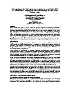
Figure 1: The user gets more detailed information pointing to one of the mounted markers.
not able to implement their brilliant ideas due to the lack of programming skills. An authoring tool solves this problem, because it enables people to produce new applications or maintain existing applications very fast and with a minimum of initial training. Indeed, artists and designers can directly work with the application and experiment with the new AR technology without the help of computer scientists. Furthermore, designers are often involved in virtual pro-
Jürgen Zauner / Authoring of Mixed Reality Applications including Multi-Marker Calibration for Mobile Devices
Figure 2: Artists don’t only want to use an AR application, but they want to modify it personally. They want to get integrated in the development process of a new AR/MR application and consequently inspire the application with their ideas and flavor the AR application with their new inspirations.
totyping (cf. figure 2). In most cases they need the help of programmers if they want to change the AR setup. In fact, a direct manipulation of the AR application seems to be an unsolvable problem. But, artists should be able to modify and tweak different properties of the application (e.g. change the surface properties of a virtual object or even change the GUI if it doesn’t look usable). In other words, artists and designers should actively manipulate their AR applications already at the beginning and they should be able to do this without the need of experts. We believe that artists are a good example of end-users that have great ideas, but they are often hindered to express themselves, because of their missing expertise in programming. 1.1. Paper overview After an overview of the related work, we present an easy to use authoring tool that helps end-users to author their AR applications (described in section 3). The authoring process starts from the concepts and includes some sub-tasks, such as placing virtual objects into the real world, setting parameters and integrating the behavior of objects. The end-user can tweak the component parameters and change the behavior. Despite authoring an AR application, the calibration setup can become a very complicated task. After the presentation of our multi marker detection system, described in section 4, we present our multi-marker calibration system in section 5. Finally, we present in 6 a placement calibration tool.. 2. Related work The possibilities for new, innovative AR applications in the entertainment area are very convincing. The EyeToy project is one of the best examples: it started with a nice prototype presented in the Emerging Technologies at Siggraph 2001 and became one of the most fascinating AR programs for the
Playstation [Mar01]. Often, artists have wonderful ideas and in the rare cases they have the possibility to express themselves. A lot of authoring tools can be found in game industry: nowadays, each game comes on the market including its own authoring tool so that players are able to create their own worlds without a lot of skills. Few commercial tools are also available in the VR field (eg. Virtools, EON Studio [Vir04, EON04]). Most of the current AR installations are based either on self-made frameworks (cf. ARVIKA, STAR, etc.), or they are based on open source frameworks (eg. Studierstube, DWARF) [WT00, SFH∗ 02, Wag01]. The DART project is built as a collection of extensions to the Macromedia Director multimedia-programming environment, and therefore primary designed for designers who want to develop their own AR applications [MMB∗ 03]. Another approach is postulated by the AMIRE project, where the authoring tools are based on a component oriented approach but not on an existing multimedia authoring tool like Director [AMI02, HZHL03, HZH02]. Together with the component oriented approach AMIRE offers different authoring tools to support end-users during their setup process for a MR application. A lot of existing AR applications use the marker detection library ARToolKit for tracking the position and orientation of virtual objects in a 3D environment. In the SignPost2 navigation project, the tracking is implemented by a combination of the ARToolKit with an inertial tracker which is particularly dedicated for fast changes in the orientation of the user [KLK∗ 02]. Unfortunately, the position and orientation of all markers are measured by hand. The same approach was used in the ASR (Augmented Sound Reality) project, where we used the marker detection system for tracking objects in the real world [HDS02, DHS02]. As described by Baratoff et al. in [BNR02] the calibration of an AR system can be very complex and has to be done with care. Of c The Eurographics Association 2004.
Jürgen Zauner / Authoring of Mixed Reality Applications including Multi-Marker Calibration for Mobile Devices
course, the calibration tasks depend on the tracking system. In our case we used the marker detection library ARToolKit [KBBM99]. Baratoff et al. distinguish four different tasks for the marker calibration that includes: • • • •
Camera calibration Single marker calibration Multiple marker calibration Match of marker and real world coordinates
In this paper we present an approach where the calibration step can be realized automatically without pre-measure the position of all markers. A similar approach is presented in [BNR02]. Mixed Reality applications are very often mobile applications. As depicted in figure 2, the visitors use a Tablet-PC setup with a camera, mounted on the back side of the device. By pointing to one of the mounted markers, visitors get 3D information relating to the adequate exhibition object. The hardware is going away from inconvenient, low resolution HMDs to easy to use, high resolution Tablet-PCs or/and mobile devices (cf. [WS03]).
Figure 3: The author can choose a component prototype from a hierarchical category to create a new component instance.
3. The generic authoring tool We have developed the generic authoring tool called CATOMIR (Component oriented Authoring Tool for Mixed Reality). It is based on the component-oriented framework of AMIRE [AMI02, HZHL03, HZH02], which is the foundation of our applications that are authored with CATOMIR. We have analyzed the authoring process of applications and encountered three basic features for an authoring tool: • Creating new components and configure their initial behavior. • Describing the workflow by connecting components (routing). • Easily calibrating the placement of all virtual content that augments the real scene. Authors analyze the application they want to build. During this analysis a set of required components will be figured out. So, the author has to take a look at the available components. If a component is missing, it can be loaded dynamically into CATOMIR. As soon as all components are available, the author can create a new component instance by choosing a so called component prototype. Therefore, CATOMIR provides a dialog (depicted in figure 3) with a hierarchical categorization of the component prototypes. These categories enable the author to lookup the desired component very easily. Next, the author has to define the initial behavior of a component by configuring all properties of the component. Figure 4 shows the generic configuration dialog for a component. Configuration properties have a specific type, which is used by the dialog to invoke specialized editors like a color c The Eurographics Association 2004.
Figure 4: The default behavior of each component can be configured by this generic property editor.
chooser for example. Further, a component developer can provide so called semantic-hints for a configuration property. A text property for example could be a simple text or a filename. So, if the text property is declared as a filename by a semantic-hint then the property dialog provides a file browser for configuration. Of course, the dialog can easily be extended by other specialized editors for a property type or a semantic-hint. Afterward, authors describe the workflow by connecting the components. Therefore, they click on an out- or in-slot and drag a new connection to a compatible in- or out-slot. In figure 5 we can see the creation of such a new connec-
Jürgen Zauner / Authoring of Mixed Reality Applications including Multi-Marker Calibration for Mobile Devices
Figure 5: The compatible in-slots are highlighted during the creation of a new connection.
Figure 6: A tooltip indicates the type and name of a slot.
tion. The small squares represent the out- (bottom) and the in-slot (top). Each slot is strongly typed. Hence, only slots of the same type can be connected. By moving the stylus (or a mouse) over a slot the type and the name of the slot will be shown as a tooltip (as seen in figure 6). Further, CATOMIR also highlights compatible slots during the connection process.
Figure 7: A detailed view of the component schema and a overview of the component schema.
view. The marker can even be occluded when an object gets between the camera and the marker (as seen in figure 8).
In contrast to EON Studios [EON04] or DirectShow GraphEdit [Mic04], we have decided to route the components in a top down style. This allows us to use the space more effectively. A component schema will become a very complex structure and the whole structure will not fit into the visible area. However, sometimes it becomes difficult to get an overview of the whole application. Thus, CATOMIR provides the feature to zoom the component schema in and out. Figure 7 gives a small impression of how complex application can get and how important zooming is during the authoring process.
Figure 8: The marker on the right side is occluded by an real object.
4. Multi-marker detection A lot of researchers use the ARToolKit library for tracking, because it is cheap and the source is available. However, this kind of tracking becomes problematic when larger areas have to be tracked. One marker is not enough to track a large area, because the marker can get out of the camera’s
The prevalent solution for this limitation of marker detection is to use several markers (as already done in [BNR02, KLK∗ 02]). We will call such a cluster of markers a multi-marker. A multi-marker is defined by the pattern and size of each marker and a transformation between c The Eurographics Association 2004.
Jürgen Zauner / Authoring of Mixed Reality Applications including Multi-Marker Calibration for Mobile Devices
4.2. Linear regression filter
Figure 9: All markers of a multi-marker refer to the blue highlighted reference-marker.
this marker and a reference point. So, each detected marker will refer to this single reference point. We have decided to use the center of the first marker of the multi-marker as the reference point, which is depicted in figure 9 (we call this marker the reference-marker). The arrows represent the transformations between the detected markers and the reference-marker, which is circled. Using such a referencemarker reduces the authoring process by the calibration of one marker. Detecting a multi-marker can be done in several ways. The easiest one is to take the marker that has been detected best. Therefore, ARToolKit provides a so called confidencefactor. We just take the information of the marker with the highest confidence-factor. However, a better solution is to consider also all other detected markers of the multi-marker, because the position and orientation of each detected marker contain small inaccuracies. In the next subsection of this paper we will present a method to get the average position and orientation of all detected markers. This method reduces the position and orientation error and combined with a linear regression of the measured data we are able to provide very stable multi-marker tracking.
4.1. Average filter For each detected marker we will get information about its position and orientation relative to the camera as a single four-by-four matrix. So, we have to extract a position vector from the matrix and a quaternion [Sho85] that represents the orientation. We do this for each marker and get the sets of positions and orientations. Furthermore, we can calculate the average position vector and the average orientation quaternion. Unfortunately, outliers in the orientation set of the detected markers have been observed. If the outliers’ percentage is getting too high then tracking will become a little instable until the outliers’ percentage is lower. Using the statistical mean value instead of the statistical average value will reduce the effect of outliers. c The Eurographics Association 2004.
Using an average filter allows us to get better tracking results for the detection of a multi-marker. However, we also want to improve the results for only one marker or stabilize the result of a multi-marker even more. Therefore, we have to consider the history of a tracking system and use a filter on a set of previous positions and orientations. We started with an average filter. This filter stabilized the orientation position very well until the marker is moved. Then a delay of all movements can be observed. With this kind of filter, a trade-off between stability and delay has to be accepted. So, we thought over our approach and applied a linear regression on a small time period of the latest marker history. The linear regression provides us with two straight lines representing the correlation between the past time and the tracked placement (position and orientation). The calculated placement at the actual time is a good approximation of the real actual placement, because using linear regression allows us to minimize the average error for the placement during this small time period. The tracking of a marker was quite stable at the idle placement of the marker and during the movement of the marker. We have observed an overshooting of the placement when the marker is moving and stops suddenly. This overshooting gets higher when the considered time period is increased. By decreasing this time period we can reduce the overshooting. But this is a tradeoff that is similar to the average filter approach. So, our next approach was to reduce overshooting by taking the placement value of an earlier time on the actual calculated placement lines instead of taking the value of the actual time. Furthermore, we consider the confidence-factor of ARToolKit for the linear regression to reduce the influence of markers that are poorly detected. By using a weighted average between the calculated placement and the placement detected by ARToolKit we are able to parameterize the influence of the currently measured placement. This final solution provides a very stable tracking of markers, especially in combination with multi-marker detection. However, the parameters of the system have to be adapted to the application scenario. 5. Multi-marker calibration In the previous section we have described what multi-marker detection is and how it works. As we have already mentioned, the multi-marker detection needs transformations between each marker and the reference-marker. Authoring this manually would be very unhandy. So, we have developed a multi-marker calibration tool, which is integrated into CATOMIR. This tool tries to detect all markers of a multi-marker. If the reference-marker is detected, the tool calculates and
Jürgen Zauner / Authoring of Mixed Reality Applications including Multi-Marker Calibration for Mobile Devices
Figure 10: The author calibrates the multi-marker on a Tablet-PC.
stores the transformations between all detected markers and the reference-marker. Further, it labels the detected markers as calibrated. Afterward, it can use the already calibrated markers to calculate the transformations between uncalibrated markers and the reference-marker. This procedure is repeated until all markers are calibrated. To stabilize the transformations the tool also recalibrates the calibrated markers by building an average transformation of all calibration steps. The calibration steps have to be explicitly activated by the author, because using each frame for the calibration would increase the weight of the camera’s positions where the author stays longer. This may lead to calibration errors. Hence, we have decided to let the author choose all calibration frames. Figure 10 shows an author calibrating a multimarker on a Tablet-PC. In figure 11 we can see the calibration step, which have to be performed by the author. Only the reference-marker is colored green, because this marker needs no calibration. After pressing the stylus onto the screen of the Tablet-PC, all red colored markers will become green. The calibration is finished when all marker are highlighted green. 6. Placement of virtual content In the previous section we have described the calibration of a multi-marker. But this calibration does not enable individual placement of virtual 3D content. So, we have developed two tools for calibration of placement. 6.1. MR placement tool This tool uses a so called placement-marker to modify the placement of the virtual content. Such a tool has already been used for the authoring of MR assembly instructions [ZHBH03]. So, we have integrated it into CATOMIR. Using
a mobile device like the Tablet-PC as target platform allows the author to examine the actual calibration of the object. The MR placement tool supports four modes (depicted in figure 12). The first one is the observation mode. This mode allows the author to take a look at the actual placement. Further, the placement-marker is visualized by a white sphere. In the second mode, the author is able to modify the size of the object. The scaling factor is proportional to the distance changes between the reference-point (e.g. the shown reference-marker) and the placement-marker. The object is scaled down by moving the placement-marker near to the reference-point and scaled up by moving the placement-marker away from the reference-point. The third mode is used to move the object. The position changes of the placement-marker are applied to the object’s position. The rotation mode, which is the forth and the last mode, enables the author to rotate the object. The orientation changes of the placement-marker are applied to the object’s orientation. Separating the position calibration from the orientation calibration allows the author to modify the placement more accurately. Furthermore, the author is able to lock the modification on a specific axis. Especially for the rotation of an object this is very useful, because the object often has to be rotated by only one axis. 6.2. The placement dialog Unfortunately, the detection of the placement-marker may fail for scenarios with bad lighting conditions. Therefore, CATOMIR provides a fallback placement dialog based on a Windows graphical user interface (cf. figure 13). 7. Conclusions and future work We have shown that authors (especially designers) are able to create new MR applications with a generic authoring tool c The Eurographics Association 2004.
Jürgen Zauner / Authoring of Mixed Reality Applications including Multi-Marker Calibration for Mobile Devices
Figure 11: The calibration steps of the multi-marker calibration (green markers are calibrated; red markers are not calibrated). The average filter places the reference-point to the center of the uncalibrated markers and the calibrated part of the multimarker.
take even longer than the description of the behavior. So, this is a very useful improvement for the authoring process of Mixed Reality applications.
Figure 13: The placement dialog.
like CATOMIR. This is even true when the author has no experiences in programming. Without the calibration features of CATOMIR the calibration would be a very complex and time consuming task. Sometimes, this calibration task could c The Eurographics Association 2004.
During our tests, we recognized that a Tablet-PC is very good solution for the authoring process. However, end-users (e.g. visitors of a museum) may prefer a smaller but lighter display (as depicted in figure 14). Hence, we are planing to port essential parts of CATOMIR and AMIRE to other mobile devices based on the operation system PocketPC 2003 like for example an iPAQ. Nevertheless, the development of the Tablet-PC version will continue. Finally, we want to give a short summary of main features CATOMIR supports: Component behavior modification: Similar to Microsoft’s GraphEdit, components can easily be dragged and dropped into the component composer. Placement tool: The virtual objects have to match the real objects. Unfortunately, possible existing CAD data can
Jürgen Zauner / Authoring of Mixed Reality Applications including Multi-Marker Calibration for Mobile Devices
Figure 12: The four calibration modes of the MR placement tool.
not be taken without any modifications. In most of the cases, a placement of these objects has to be done manually. An easy to use placement tool helps the author during this task. Component routing: Objects can have a behavior. Thus a component routing tool allows to connect two objects via their slots. Calibration support: Finally, the application has to be calibrated. The calibration depends on the hardware setup. In our case we used the multiple marker based tracking system. References [AEC04] AEC: Ars Electronica http://www.aec.at. 1
Center,
2004.
[AMI02] AMIRE C ONSORTIUM: AMIRE - Authoring Mixed Reality, 2002. http://www.amire.net. 2, 3 [BFSE01] B IMBER O., F RÖHLICH B., S CHMALSTIEG D.,
E NCARNAÇÃO L. M.: The virtual showcase. IEEE Comput. Graph. Appl. 21, 6 (2001), 48–55. 1 [BNR02] BARATOFF G., N EUBECK A., R EGENBRECHT H.: Interactive multi-marker calibration for augmented reality applications. In IEEE / ACM International Symposium on Mixed and Augmented Reality, ISMAR 2002 (2002), IEEE Computer Society. 2, 3, 4 [DHS02] D OBLER D., H ALLER M., S TAMPFL P.: ASR - Augmented Sound Reality. In ACM SIGGRAPH 2002 Conference Abstracts and Applications (2002), p. 148. 2 [EON04] EON-R EALITY: Eon-reality webpage, 2004. http://www.eonreality.com/. 2, 4 [HDS02] H ALLER M., D OBLER D., S TAMPFL P.: Augmenting the Reality with 3D Sound Sources. In ACM SIGGRAPH 2002 Conference Abstracts and Applications (2002), p. 65. 2 c The Eurographics Association 2004.
Jürgen Zauner / Authoring of Mixed Reality Applications including Multi-Marker Calibration for Mobile Devices
S ZALAVARI Z., E NCARNAÇÃO L. M., G ER P URGATHOFER W.: The Studierstube augmented reality project. Presence: Teleoper. Virtual Environ. 11, 1 (2002), 33–54. 2 VAUTZ M.,
[Sho85]
S HOEMAKE K.: Animating rotation with quaternion curves. In Proceedings of SIGGRAPH’85 (July 1985). 5
[Vir04]
V IRTOOLS: Virtools-Webpage, http://www.virtools.com/. 2
2004.
[Wag01] WAGNER M.: DWARF – Design, Prototypical Implementation and Testing of a Real-Time Optical Feature Tracker. Master’s thesis, Technische Universität München, Department of Computer Science, Feb. 2001. 2 Figure 14: A smaller and lighter target platform for museum applications.
[HZH02] H ALLER M., Z AUNER J., H ARTMAN W.: A generic framework for game development. In Proceedings of the ACM SIGGRAPH and Eurographics Campfire (Snowbird, Utah, USA, June 2002). ISBN 3-8322-0241-2. 2, 3 [HZHL03]H ALLER M., Z AUNER J., H ARTMANN W., L UCKENEDER T.: A generic framework for a training application based on Mixed Reality. Technical report, Upper Austria University of Applied Sciences (MTD), 2003. 2, 3 [KBBM99]K ATO H., B ILLINGHURST M., B LANDING B., M AY R.: ARToolKit. Technical report, Hiroshima City University, December 1999. 2 [KLK∗ 02]K ALKUSCH M., L IDY T., K NAPP M., R EITMAYR G., K AUFMANN H., S CHMALSTIEG D.: Structured visual markers for indoor pathfinding. In Proceedings of the IEEE First International Workshop on ARToolKit (2002). 2, 4 [Mar01] M ARKS R.: Enhanced Reality: A new frontier for computer entertainment. In ACM SIGGRAPH 2001 Conference Abstracts and Applications (2001), p. 117. 2 [Mic04] M ICROSOFT: Microsoft developer network webpage - directshow graphedit, 2004. http://msdn.microsoft.com. 4 [MMB∗ 03]M AC I NTYRE B., M ARIBETH G., B OLTER J. D., D OW S., H ANNIGAN B.: Dart: The designer’s augmented reality toolkit. In IEEE / ACM International Symposium on Mixed and Augmented Reality, ISMAR 2003 (2003), IEEE Computer Society, pp. 329–330. 2 [SFH∗ 02] S CHMALSTIEG D., F UHRMANN A., H ESINA G., c The Eurographics Association 2004.
[WS03]
WAGNER D., S CHMALSTIEG D.: First steps towards handheld augmented reality. In Proceedings of the 7th IEEE International Symposium on Wearable Computers (2003), IEEE Computer Society, p. 127. 3
[WT00]
W OHLGEMUTH W., T RIEBFUERST G.: Arvika: augmented reality for development, production and service. In Proceedings of DARE 2000 on Designing augmented reality environments (2000), ACM Press, pp. 151–152. 2
[ZHBH03]Z AUNER J., H ALLER M., B RANDL A., H ARTMANN W.: Authoring of a Mixed Reality Assembly Instructor for Hierarchical Structures. In Proceedings of the Second IEEE and ACM International Symposium on Mixed and Augmented Reality (Tokyo, Japan, October 2003). 6