secondly, by building a control system for the wheelchair in order to achieve d=0 and Ï=0 before .... University of Pittsburgh, Forbes Tower,. Pittsburgh, PA ...
Automatic Kerb Detection for Assistance in Navigation Loreto Susperregi1 , Ander Ansuategi1 , Nerea Alberdi1 , Inés Garmendia 1 , Carlos Tubio 1 , Basilio Sierra 2 , Elena Lazkano2 1 Fundación Tekniker 2 UPV, Informatika Fakultatea
Abstract: Kerbs are one of the main architectural barriers that people with disabilities, especially wheelchair users, encounter in urban areas. Accordingly, this paper’s main aim is to present a solution to kerb detection that will be integrated as an assistive function on a motorized wheelchair. Keywords : wheelchair, machine learning, kerb, navigation
Introduction Kerbs or steps (both indoors and outdoors) constitute one of the most common architectural barriers. To attempt to climb a step or the kerb in a wheelchair involves a complex manoeuvre, as it means bringing the wheelchair as perpendicular as possible to the step and suitably adjusting the power of the motors to climb it. The manoeuvre for negotiating this obstacle also presents a problem of safety, as if it is not carried out properly it might lead to loss of control of the wheelchair, thereby endangering both the person sitting in it and anyone accompanying them. There are numerous projects within the sphere of motorised wheelchairs, many of which focus on autonomous navigation avoiding both static and moving obstacles [1]. However, few address the detection of “special” obstacles, such as holes or kerbs [2]. The present paper is part of the development of a high-performance wheelchair designed by TEKNIKER. High-performance here is understood to mean the full development of a motorised wheelchair, with one of the key points being that the user has a single powered wheelchair for use both indoors and outdoors and fitted with features associated with new technologies as “technical aids”. The solution addressed in this article involves resolving the problem of detecting the kerb, as well as recording the wheelchair’s positioning regarding the obstacle and, finally, the definition of the control for the correct manoeuvre when negotiating this obstacle semi -automatically. The article has the following structure: the second section considers the problem of detecting kerbs, the next section deals with the study made on the simulator, the fourth section describes the experimental platform used and the pattern of experiments undertaken, followed by the results obtained and, finally, the conclusions.
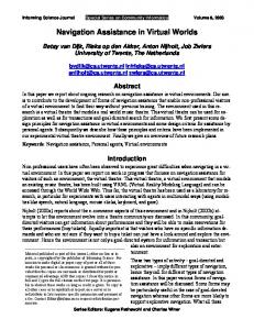
1. Considering the problem The problem is addressed on two levels: firstly, by gathering enough information to provide a profile of the kerb and be able to establish wheelchair position (d, φ), and secondly, by building a control system for the wheelchair in order to achieve d=0 and φ=0 before starting kerb climbing. KERB
d
F
Fig. 2 Problem representation
1.1. The sensors: selection and positioning The main aim in this case is to measure distances, both between the wheelchair and the kerb and the height of the same. Accordingly, an analysis has been made of the state-of –the-art in the field of sensors, studying the applicability of four types of sensors: infrared, ultrasound, laser and cameras. Several requirements are established for the sensors, such as the range of distances to be measured, resolution, accuracy, response time, power consumption, size and cost. Table 1 summarises the main conclusions. Description
Advantages
Disadvantages
Infrared
Direct reading of the distance to the obstacle. Small size and low cost.
It does not provide a suitable reading for kerb height and it has a narrow range of distances. Several sensors are required.
Ultrasounds
Direct reading of the distance to the obstacle. Small size and low cost.
Several ultrasounds are required in a small area and the signals may overlap. It does not provide a suitable reading for kerb height.
Laser
Suitable range of distances. Initially, it allows for measuring the height of the kerb and the distance to it, as it emits a signal beam.
High cost compared to other cheaper types of sensor.
Cameras
It detects the kerb fairly accurately.
Complex image processing for detecting the kerb. High computatio nal cost.
Table 1. Outline of advantages and disadvantages of the different types of sensors
The laser sensor is the one most suited to the needs the problem poses, and as a consequence a HOKUYO URG-04LX laser sensor was chosen because of its low cost (compared to other lasers), small size and low consumption, making it the most appropriate one for fitting onto a motorised wheelchair. The position of the sensors is a crucial factor for determining the strategy for kerb detection. After analysing the various alternatives in several projects [3][4][5] in which sensors were fitted onto wheelchairs, the decision was taken to use the most unintrusive solution possible, placing the laser sensor below the armrest as it is shown in figure 1.
Figure 1. Sensor position
1.2. Design of experiments The design of experiments includes gathering data at various distances from the kerb and for different positions of the wheelchair with regard to it. Specifically, measurements have been taken every 20 cm in the range of 1m to 20cm away, angling the wheelchair between [-45, -30, -15,-5, 0, 5, 15, 30, 45] degrees towards the kerb.
2. Simulation The simulation creates a specific environment that is similar to the real one with an 8 cm kerb, allowing for simulating both sensor readings and the wheelchair’s movement in order to analyse different alternatives. Two different ways of collecting the laser’s readings have been considered: a vertical one, where readings are taken at right-angles to the ground, and a horizontal one, at an angle of 15 degrees to the ground, shown in figure 2.
Figure 2. Depiction of the types of readings considered
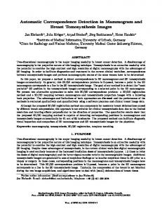
The result of the simulation is a series of data comprising the readings of the laser sensor when emitting a 180º signal beam from the wheelchair, with a 1º interval in the angle between two consecutive readings. As an example, figure 3 shows the result obtained by a vertical reading taken at right-angles to the kerb at a distance of 80 cm. A change in the gradient is detected when the beam cuts the kerb. Distance 80cm, orientation 0º 1600
1400
1200
Reading
1000
800
600
400
200
0 1
2
3
4
5
6
7
8
9
10
11
12
13
14
15
16
17
18
19
20
Beam angle
Figure 3. Readings obtained at 80 cm vertically at right-angles to the kerb
21
22
23
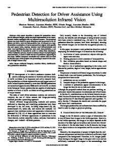
3. Experimental platform Real-life experiments have been carried out with a SUNRISE wheelchair fitted with a HOKUYO laser sensor. A testing platform has been designed for conducting the experiments, whereby the laser’s true performance can be compared to the data provided by the simulation and data are captured for creating the wheelchair’s control algorithms in the manoeuvre for climbing the kerb. The platform consists of a real stone kerb of around 10 cm in height that can be adjusted between 2 and 10 cm. 3.1. Data acquisition and pre-processing The pattern of experiments is similar to that arranged for the simulation, with two significant differences. The first is that as there is noise in the readings, the decision is taken to use a filter that applies a restricted average of 20 to 100 readings taken in each position. The second is that the angular field for data gathering from the laser beam has been restricted in order to minimise the capture of irrelevant data, with a vertical limit of 60º from the horizontal (equal to 176 readings) and 100º horizontally. The graph in figure 4 plots the data obtained with the real sensor at a distance of 80 cm from the kerb in the vertical and horizontal positions. The result is a similar curve to the one obtained in the simulation where, in the vertical case, the same gradient variation can be observed when the kerb area is reached. Distance 80cm Angle 0º
1800
Kerb
1600 1400
Distance
1200 1000 800 600 400 200 0 1
8
15 22 29 36 43 50 57 64 71 78 85 92 99 106 113 120 127 134 141 148 155 162 169 176 Beam angle
Figure 4. Vertical readings obtained at the real platform at 80cm in right angle to the kerb.
Once the data have been obtained for all the situations contemplated in the design of experiments, they are pre -processed in order to enhance the characterisation of the kerb’s presence, height and the wheelchair’s positioning with regard to it. Figure 5 provides a summary of the data obtained based on the pre-processing, with plotting of the reading points that detect the beginning and end of the kerb for the various distances and different angles. Punto de fin de bordillo
Kerb starting point
Angle
Angle
Distance
Distance -45 112 85 61 44
40 60 80 100
-30 125 95 73 56
-15 139 107 81 61
-5 138 104 78 62
0 131 106 80 63
5 132 102 78 60
15 126 98 76 58
30 110 89 67 51
45 96 79 62 50
160
-45 98 74 54 40
40 60 80 100
-30 112 82 63 49
-15 126 95 71 55
-5 126 91 68 55
0 119 93 70 56
5 120 90 69 53
15 113 86 66 50
30 97 78 58 45
45 84 70 55 45
140
140
120
120 40 60 80 100
100 80 60
100 40 60 80 100
80 60 40
40 20
20
0 -45
-30
-15
-5
0
5
15
30
45
0 -45
-30
-15
-5
0
5
15
Figure 5. Summary of results for the beginning and end of the kerb
30
45
3.2. The algorithms The relationship between the measurements made by the laser sensor and its position regarding the kerb is addressed through the use supervised classification algorithms as they are better at handling the uncertainty existing in the data obtained experimentally. The training data are based on those recorded in the design of experiments, where the input are the readings taken by the laser sensor and the output is the command control for moving the wheelchair, with this command being proportional to its angle to the kerb. The tool used for this phase is WEKA, where a battery of algorithms is tested and validated using the data obtained in the experimentation.
4. Conclusions The results obtained from real data indicate that: • Experimentation confirms that capturing data with the sensor vertically improves the characterisation of the kerb. • Regarding the wheelchair’s positioning, the data reveal a clear relationship between wheelchair angle and the readings obtained by the sensor, although there is a degree of greater uncertainty in the area around 15º. • As for kerb height, an area has been identified in which the beginning and end of the kerb can be detected as shown in figure 8, whereby its height can be measured. Finally, the control seeks to bring the wheelchair at right-angles to the kerb, as this is a critical factor when negotiating this obstacle.
ACKNOWLEDGMENT This work was supported in part by OBRA SOCIAL KUTXA. Authors thank the technical support of the Mechatronics Department of TEKNIKER and to Armando Díaz and Enrique Viruega fro m SUNRISE MEDICAL.
References [1] Richard C. Simpson, “Smart wheelchairs: A literature review“. Journal of Rehabilitation Research and Development, Volume 42 Number 4, July/August 2005 Pages 423-438 [2] Stephen Hayashi1, Edmund F. LoPresti1, Richard Simpson1, Illah Nourbaksh, David Miller, “An Inexpensive, Alternative, Drop-off Detection Solution [3] A Description of the SENA Robotic Wheelchair. Gonzalez J., Muñoz A.J., Galindo C., FernandezMadrigal J.A., and Blanco J.L.. System Engineering and Automation Department. University of Malaga. Spain [4] The Smart Wheelchair Component System. Richard Simpson, PhD, ATP; Edmund LoPresti, PhD; Steve Hayash i, PhD; Illah Nourbakhsh, PhD; David Miller, PhD. University of Pittsburgh, Forbes Tower, Pittsburgh, PA; Assistive Technology Sciences, Pittsburgh, PA; Robotics. Institute, Carnegie Mellon University, Pittsburgh, PA; University of Oklahoma and KISS Instit ute for Practical Robotics, Norman, OK. [5] Sensors to Improve the Safety for Wheelchair Users. Klaus Schilling, Hubert Roth, Robert Lieb, Hubert Stützle. FH Ravensburg-Weingarten, Postfach 1261, D-88241 Weingarten.