work cells with industrial robots, e.g., in the car in- ... formed into a real robot program according the .... deviations of the mechanics, e.g., elasticity of the gear and ...
mingham, United Kingdom, 27th-30th April 1998.
Automatic off-line programming and motion planning for industrial robots Heinz WÖRN, Christian WURLL and Dominik HENRICH∗ Abstract - This paper discusses the problem of automatic off-line programming and motion planning for industrial robots. At first, a new concept consisting of three steps is proposed. The first step, a new method for on-line motion planning is introduced. The motion planning method i s based on the A*-search algorithm and works in the implicit configuration space. During searching, the collisions are detected in the explicitly represented Cartesian workspace by hierarchical distance computation. In the second step, the trajectory planner has to transform the path into a time and energy optimal robot program. The practical application of these two steps strongly depends on the method for robot calibration with high accuracy, thus, mapping the virtual world onto the real world, which is discussed in the third step.
Due to these disadvantages of today’s off-line robot programming methods, a new approach will be discussed in this paper. The paper is organized as follows: In Section 2 a new approach for off-line programming of industrial robots is introduced. Section 3 describes a powerful parallel motion planner. Section 4 presents the requirements for an optimal trajectory execution. Section 5 discusses a new approach to the necessary robot calibration. The paper ends with the conclusion and an outlook of the future investigation in Section 6.
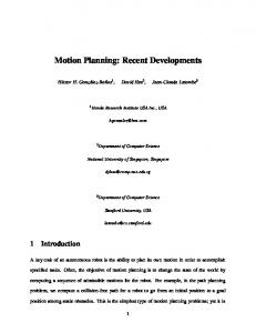
2 . Automatic off-line programming In order to avoid idle times of capital intensive installations, the programming of the industrial robots must be performed off-line in a virtual world. Today, robot simulation is often applied for designing work cells with industrial robots, e.g., in the car industry (Fig. 1).
Keywords: off-line programming, motion planning, trajectory optimization, robot calibration 1 . Introduction Today, industrial robots are often used in complex and capital intensive installations in big industries (i.e. car industry) and their supplier companies. For an economic rentability of these expensive installations, short programming and low cycle times are necessary. This implies, for example, for spot welding, object handling or assembly, the fast as possible collision-free movement of the robot. Even now, industrial robots are programmed manually by the „Teach-in“ method. During this programming time, the capital intensive installations cannot be used at all. Afterwards, a time consuming optimisation of the programmed trajectory follows, for example by an iterative adaptation of the velocity profiles. The result is an optimised trajectory which strongly depends on the programmers experience.
∗
Fig. 1: Robot simulation of an industrial work cell In the virtual world, the robot work cell is modelled by workpieces, robots, tools and periphery. The aim of this investigation is, e.g., to determine the position of the robot, the tools and the clamping devices and to determine and optimize the cycle time. Based on this modelling, all parts existing in the virtual world can directly be used to program the real robot. Firstly, based on the given CAD model and the construction plan, it is possible to automatically compute a collision-free path in order to reduce the programming time and to increase the pro-
Institute for Process Control and Robotics (IPR), o. Prof. Dr.-Ing. H. Wörn, University of Karlsruhe, Department of Computer Science, P.O. Box 69 80, D-76128 Karlsruhe, Germany, E-Mail: [woern, wurll, dHenrich]@ira.uka.de
gram quality. Secondly, this collision-free path must be optimised for a fast path execution and transformed into a real robot program according the robot’s language. Thirdly, an essential precondition for this approach is the possibility of calibrating the virtual world with the real world.
→
ΘS
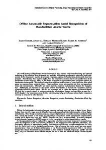
3 . Motion planning with collision avoidance The issue of robot motion planning has been studied for a couple of decades and many important contributions to the problem have been made [1]. Motion planning algorithms are of great theoretical interest, but are rarely used in practice because of their computational complexity [2]. Most of the off-line motion planners are based on an explicit representation of the free C-space. The free C-space computation consists of the obstacle transformation into the C-space and the construction of a free-space representation. Both tasks are very timeand memory consuming, and their calculation effort increases with the robots DOF. In order to avoid these time consuming obstacle transformations, one can search in an implicitly represented C-space and detect collisions in the workspace. This strategy enables the planner to cope with on-line provided environments, moving obstacles and grasped objects. For searching in the implicit C-space, we apply the well known A*-search algorithm. The main task of the A*-algorithm consists of the expansion and the processing of configurations, which are saved in the priority list OPEN. In every iteration, the best configuration of OPEN is expanded. According to a heuristic evaluation function, these successors will be considered in the following iterations. After the expansion, the parent configuration is saved in the hashing table CLOSED. The search continues until the goal is found or the OPEN list is empty. In the latter case the algorithm stops with no solution. In Fig. 2a, an example for a 2D search is given. The dots indicate investigated configurations and the arrows give reference to the corresponding successors. Collisions are detected by a fast, hierarchical distance computation in the 3D workspace, based on the given CAD model of the environment and the robot [3] (see Fig. 2b). With the help of the "maxmovetables", introduced in [4], the Cartesian distances are then transformed into joint intervals in order to define the state ("free" or "prohibited") of the regarded configuration.
1 →
(a)
ΘG
2
4 3
(b) Fig. 2: (a) A*-search in r the implicit C-space from the start configuration Θ S to the goal configuration
r Θ G . (b) Collision detection by distance computation in the workspace
For obtaining similar joint intervals, which implicates an efficient distance exploitation, the optimal joint discretisation is automatically computed based on the method of [5]. For speeding up the motion planner, we have parallelized the A*-search algorithm and implemented it on a PC-based workstation cluster [6]. Further details about the planner and the achieved planning times can be found in [7].
4 . Time optimal path planning During the path planning, only the kinematics of the robots has been regarded. In the following trajectory planning, optimal velocity profiles must be computed. This is necessary for a time- and energy optimal path execution. Hereby, several robot constraints like maximal joint velocities, maximal joint accelerations, admissible motor- and gear moments etc. have to be considered. Due to the geometry of the robot and its physical parameters, large non-linear equation systems for a required accuracy must be optimally solved.
5 . Robot calibration The robot calibration has the most important influence for an acceptance of the off-line programming, because only if the virtual world can exactly be
mapped onto the real world, the automatically computed programs can be used in practice. tool TCP goal position
In [8] a calibration process is developed, which fulfils this requirement. It uses a static robot model containing as parameter the physical effects which lead to the deviation. These parameters p1, …, pn must be identified for every robot by measuring them. About 70 points spread over the entire working area are measured by theodolites in the Cartesian space and stored with the actual positions of the joints (Fig. 5). The result is a robot model which generates the real position including the deviations.
F( p1 , p2 ,K , pn ) = TCPm ( x, y, z ) m = 1K 70 workpiece
robot
world
Fig. 4: Illustration of the robot calibration task In the calibration task (Fig. 4), the position of the robot related to the workpiece must be measured. The workpiece model, e.g. a car body, must correspond exactly enough with the real workpiece. The position of the workpiece must be exactly measured. The main problem are the tolerances of the robot. Since the measuring system of the robot measures the position of the rotor axis of the motors, the entire deviations of the mechanics, e.g., elasticity of the gear and manufacturing inaccuracies, are not considered. Concerning „Teach-in“ these deviations are completely compensated since the Tool Center Point (TCP) with original load is observed by the human programmer. When creating points in the virtual world, the effect appears as a real error. The necessary total accuracy, e.g., in spot welding, must be between 2 to 2.5 mm. Regarding the robot, the absolute accuracy must be less than 1 mm. processing unit measure programm
desired position Theodolits position measure
actual position TCP
TCP actual position axis
actual position axis
Theodolits
Fig. 5: Measurement setup for the acquisition of robot model parameter
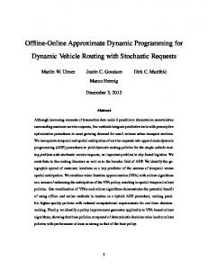
Fig. 6 illustrates this method and the modelling. Starting at the virtual TCP, the positions of the joints are calculated by the means of the inverse transformation. Then, the forces and torques having effect on the joints are calculated by a simple static model on the basis of the payload of the robot and the robot parts. Measurements on big robots with 150 kg payload have shown that an absolute accuracy up to 0.7 mm is possible with this method [9]. In many applications, an accuracy of about 0.7 mm are not enough. Improving this accuracy by physical models is very complex. A neuronal network which is trained with the desired virtual points (command points) and the absolute measured points (actual points) is expected to improve the absolute accuracy.
5 . Conclusion and future work In this paper, we have introduced a new approach to automatic off-line programming for industrial robots. The new concept proposes a three-step-plan for solving the task. Based on a given CAD model of a capital intensive installation, a parallel motion planner is able to compute a collision-free path to speed up the off-line programming phase and to support the human programmer. In the second step, a trajectory planner transforms the computed path into a real robot program, optimising the path execution. Nevertheless, these two steps are only successful, if the virtual model exactly corresponds to real environment. Thus, a powerful robot calibration with high accuracy is necessary in the third step. In our future work, we focus on developing these three modules to build up the complete automated off-line programming system. Concerning the existing motion planner, we will concentrate on a hierarchical discretisation of the configuration space for speeding up the planning times [10]. Currently, we investigate different trajectory optimisation method, especially manipulating of polygons [11]. Concerning the robot calibration, we will check if a neuronal network may show good results.
Modell of the physical effects: TCP-desired
gear elasticities 0.8
Inverse transformation
TCP
w2g 1E-4 rad
axis 3
F
0.4 axis angle w2
50 Nm
moment calculation M1...M6
w2g = p1M - p2sign(M)SQRT(ABS(M)) axis 2
parts elasticities F
payload
M T
mass of the robot's parts
F=DT arm length: Offset : p4 zero position: Offset : p5 joint translation: p6, p7, p8
axis angle
joint rotation: p9, p10, p11
axis 1
D
Fig. 6: The method for modelling and calibrating the industrial robot
Acknowledgement Part of this work was done in the project "Scalable algorithms for parallel motion planning in dynamic environments", funded by the German Basic Research Framework (DFG-Schwerpunktprogramm) "Efficient algorithms for discrete problems and their applications". Further information can be found at the Web page of the PaRo group (Parallel robotics) of the IPR at http://wwwipr.ira.uka.de/˜paro/.
References [1] Hwang Y. K., Ahuja N., "Gross motion planning – A survey", ACM Computing Surveys, vol 24, no 3, Sept. 1992. [2] Kamal L., Gupta K., del Pobil, A.P.: „Practical motion planning in robotics: Current approaches and future directions“, IEEE Robotics & Automation Magazine, Dec. 1996. [3] Henrich D., Cheng X., "Fast Distance Computation for Online Collision Detection with Multi-Arm Robots", IEEE International Conference on Robotics and Automation, Nice, France, May 10.-15., pp. 2514-2519, 1992. [4] Katz G.: „Konzeption einer Entwicklungsumgebung unter ROBCAD für die parallele Bewegungsplanung“, Diplomarbeit, Institut für Prozeßrechentechnik und Robotik, Universität Karlsruhe, 1997.
[5] Qin C., Henrich D.: „Path planning for industrial robot arms - A parallel randomized approach“, In Proc. of the International Symposium on Intelligent Robotic Systems (SIRS´96), Lissabon, Portugal, pp. 65-72, July 22-26, 1996. [6] Wurll C., Henrich D.: „Ein Workstation-Cluster für paralleles Rechnen in Robotik-Anwendungen“, In: APS´97, 4. ITG / GI Fachtagung Arbeitsplatz-Rechensysteme, Koblenz-Landau, 1997. [7] Wurll C., Henrich D., Wörn H.: „Parallel on-line motion planning for industrial robots“, In Proceedings of Robotics 98: The Third ASCE Specialty Conference on Robotics for Challenging Environments, Albuquerque, New Mexico, April 26-30, 1998. [8] Schröer K., Bernhardt R., Albright S., Wörn H., Kyles S., Albada D.V., Smyth J., Meyer R.: „Calibration applied to quality control in robot production“, IEEE Robotics and Automation, 1992. [9] Stark G., Benz E., Hüttendorfer M.: „Calibration Experiences in Industry“, Internal summery of EPSRIT II CAR (5220), KUKA Schweißanlagen + Roboter GmbH, 1992. [10] Osterroht T.: „Hierarchische parallele Bewegungsplanung für dynamische Umgebungen“, Diplomarbeit (in Bearbeitung), Institut für Prozeßrechentechnik und Robotik, Universität Karlsruhe, 1998 [11] Bordon U.: „Parallele Glättung von Robotertrajektorien“, Studienarbeit in Bearbeitung, Institut für Prozeßrechentechnik und Robotik, Universität Karlsruhe, 1997.