Hydrol. Earth Syst. Sci., 14, 1767–1771, 2010 www.hydrol-earth-syst-sci.net/14/1767/2010/ doi:10.5194/hess-14-1767-2010 © Author(s) 2010. CC Attribution 3.0 License.
Hydrology and Earth System Sciences
Technical Note: Automatic river network generation for a physically-based river catchment model S. J. Birkinshaw School of Civil Engineering and Geosciences, Newcastle University, Newcastle upon Tyne, NE1 7RU, UK Received: 10 May 2010 – Published in Hydrol. Earth Syst. Sci. Discuss.: 31 May 2010 Revised: 24 August 2010 – Accepted: 9 September 2010 – Published: 17 September 2010
Abstract. SHETRAN is a physically-based distributed modelling system that gives detailed simulations in time and space of water flow and sediment and solute transport in river catchments. Standard algorithms for the automatic generation of river channel networks from digital elevation data are impossible to apply in SHETRAN and other similar models because the river channels are assumed to run along the edges of grid cells. In this work a new algorithm for the automatic generation of a river channel network in SHETRAN is described and its use in an example catchment demonstrated.
1
Introduction
There is a long history of research that has been carried on the automatic generation of river networks from digital elevation models (DEM’s) (Jenson and Domingue, 1988; Tarboton et al., 1991). There are three parts in a typical procedure (Grimaldi, 2010). Firstly, to remove the pits from a DEM, secondly, to calculate the flow directions for each grid square and, thirdly, using the flow directions to extract the river channel network. A number of algorithms exist for the removal of pits (Grimaldi et al., 2007) although some can result in flat areas which can cause problems when generating river networks (Nardi et al., 2008). A considerable number of different methods exist for the calculation of flow directions; some of these are compared in Erskine et al. (2006). In a single-direction algorithm the upstream contributing area is calculated by considering that all the flow is transferred from one cell to its downslope neighbour, whereas in multiple-direction algorithms the flow can be portioned to several neighbouring cells. The D8 (O’Callaghan and Mark, 1984) method is a single flow direction method Correspondence to: S. J. Birkinshaw (
[email protected])
in which each cell discharges into one of its eight neighbours (4 sides and 4 vertices), the one located in the direction of steepest descent. The ρ8 method is also a single flow direction method which randomly assigns the direction of flow to the downslope neighbours with the probability proportional to the slope. Multiple flow methods include the MD8 method (Quinn et al., 1991), DEMON (Costa-Cabral and Burges, 1994), D∞ (Tarboton ,1997) and MD∞ (Seibert and McGlynn, 2007). Multiple flow methods appear to generally produce better results (Erskine et al., 2006; Wilson et al., 2007). The basic method to extract the river channel network is then to use the flow directions to calculate the upstream contributing area for each grid square and then initialise a river channel when the upstream contributing area is greater than a threshold value (Montgomery, 1993). However, automated methods are available for channel initialisation (Tarboton et al., 1991; Lin et al., 2006). For example, Tarboton et al. (1991) used a constant drop analysis for the identification of the channel initialisation threshold and then the river channel network is extracted using a curvaturebased scheme (Tarboton and Ames, 2001). Many hydrological models for water flow in a river catchment make use of the upstream contributing area and the automatic generation of the river channel network. In TOPMODEL (Quinn et al., 1991) the topographic index depends on the upstream contributing area. ArcHydro (Maidment, 2002) is a geospatial and temporal model that is based around the automatically generated river channel network, it is not itself a simulation model but it supports hydrological simulation models. Some lumped hydrological models split the catchment into sub-catchments or response units and these can be automatically generated in a GIS using the above techniques, e.g. ArcGIS-SWAT (Olivera et al., 2006) and WATFLOOD (Shaw et al., 2005). In some distributed hydrological models the channels can be defined using the above techniques. For example, in Thales (Neumann et al., 2010) the upstream contributing area is calculated using a D∞ method
Published by Copernicus Publications on behalf of the European Geosciences Union.
1768
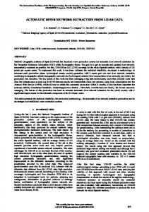
S. J. Birkinshaw: Automatic river network generation contain surface waters and the vegetation canopy. Figure 1a shows the tops of the columns in plan view, and also shows how the river channel network lies along the edges of the surface finite difference cells. Setting-up the river channel network has traditionally been carried out manually with the data input into text files. This time consuming activity was prone to error. For example, it was easy to define a catchment in which the river network was not connected or a catchment in which there was not a downward flow pathway for water in the river channel. A Graphical User Interface (GUI) for SHETRAN has been developed (Birkinshaw et al., 2010) and this allows a prototype simulation to be produced rapidly giving a starting point for detailed work. A key part of the GUI is the automatic generation of the river channel network and this is described here.
3 Fig. 1. Gais Gill Catchment, Upper Eden, Northern England. (a) SHETRAN mesh (50 m grid squares) (b) map of catchment.
and a channel is defined if the upstream contributing area is greater than a threshold value. In this case the entire grid square is considered to be a channel element. However, in some physically based distributed models (PBDM’s), e.g. SHETRAN (Ewen et al., 2000) and MIKE SHE (Graham and Butts, 2006), the channel runs along the edge of the grid square. In these models the standard techniques used above to generate a river channel network do not work This work describes a new algorithm for the automatic generation of river channel networks for a PBDM where the river channel runs along the edge of grid squares. It is based on SHETRAN but could be applied to any similar model. 2
SHETRAN
SHETRAN (www.ceg.ncl.ac.uk/shetran) is a PBDM for water flow, sediment and solute transport in river catchments (Ewen et al., 2000) which includes hydrological components for simulating: rainfall interception by vegetation; evaporation and transpiration; snowpack formation and snowmelt; overland and channel flow; variably saturated subsurface flow; and river/aquifer interactions. It solves the governing, physics-based, partial differential equations for flow and transport on a rectangular finite difference grid. Examples applications include: Birkinshaw and Webb (2010) and Birkinshaw and Bathurst (2006). The most convenient way of thinking about SHETRAN is that it represents the catchment as a set of columns, with each column divided into a stack of finite difference cells. The lower cells contain aquifer materials and groundwater, higher cells contain soil and soil water, and the uppermost cells Hydrol. Earth Syst. Sci., 14, 1767–1771, 2010
River network generation
The procedure for the automatic generation of the river channel network in SHETRAN is different than typical approach (a “grid network”), because the river channels flow along the edge of the grid squares (an “edge network”). A simple method to produce the required “edge network” would be to follow an edge (say the “right bank”) of the “grid network” produced using a typical approach (Grimaldi, 2010). But methods attempted following this approach produced channel networks that were not connected. Therefore, the following procedure for the automatic generation of the river channel network in SHETRAN has been developed. Initially this follows a typical approach (Grimaldi, 2010): the pits in the DEM are removed, the flow directions are calculated and this gives an upstream contributing area for each grid square, and a procedure for channel extraction is defined (basic methods are used here and these are discussed in detail below). Figure 2 shows a simple example on a 5 by 5 grid, and assumes that all the grid cells are within the catchment and that the threshold value for channel initialisation is 2 grid squares. The algorithm proceeds as follows: 1. The lowest cell is assigned as the outlet. In Fig. 2a this is cell (4,1) at 103 m. 2. Remove DEM pits by increasing their elevation until they are higher than one of their neighbours. There are no pits in Fig. 2a. 3. Calculate the flow directions along the steepest downhill gradient (only north-south and east-west flows allowed), and use this to give the upstream contributing area for each cell (Fig. 2b). 4. Use the results from 3 to calculate the upstream contributing area for each grid corner, as the maximum seen www.hydrol-earth-syst-sci.net/14/1767/2010/
S. J. Birkinshaw: Automatic river network generation
1769
Fig. 2. Automatic generation of river channel network for a 5 by 5 example. (a) DEM data (m), (b) upstream contributing area for each grid cell, (c) upstream contributing area for each cell corner, (d) add first channel, (e) add second channel, (f) add third channel.
in the cells that meet at the corner (Fig. 2c). The upstream contributing area in outlet corners (4,1) and (5,1) are increased by one. 5. Systematically work through all the cells, starting from the highest, initiating channels where appropriate. The details of the approach are demonstrated in “a” to “c” below and in Fig. 2b to 2f. For any cell, a river channel is initiated if the upstream contributing area is greater than or equal to the threshold value for channel initialisation. This channel is then followed downhill, from corner to corner, taking the route of maximum upstream contributing area, until the outlet or another river channel is reached. (a) In Fig. 2b the first river channel starts at cell (4,5) with an elevation of 113 m and an upstream contributing area of 2. The channel (Fig. 2d) is located along the side of the cell, starting at corner (5,6) and going to corner (5,5) [the channel is located on the eastern side of the cell rather than the western side because the adjacent grid square has a lower elevation, 125 m at cell (5,5) compared to 126 m at cell (3,5)]. Of all the corners connected to (5,5) the highest accumulation is at (5,4), so the channel goes to (5,4), and so an all the way to the outlet at (5,1). (b) The next cell to initiate a channel is (2,4), with an elevation of 112 m and an upstream contributing area of 3 (Fig. 2e). The process proceeds as before. To maximise the flow accumulation, the channel starts at corner (2,5) and goes to (2,4), then (2,3), (3,3) and (4,3). It is now only one cell away from the existing channel, Instead of following the www.hydrol-earth-syst-sci.net/14/1767/2010/
usual rule and going to (4,2), it goes to join the existing channel at (5,3). The maximum upstream contributing area rule is here overridden by a rule demanding maximum connectedness. (c) The third and final cell to initiate a channel is (3,2), with an elevation of 105 m and a flow accumulation of 2 (Fig. 2f). The channel starts at corner (3,2), uses the maximum flow accumulation rule to go to (4,2), then uses the maximum connectedness rule to go to (5,2). The elevations and widths of the channels are calculated automatically. The elevations are calculated during the above procedure by initially setting the base of the channel to be a set distance below the lowest adjacent grid cell (user defined parameter) and then, if necessary, reducing it so that it is lower than the upstream channel elevation (this procedure is fairly simple as the algorithm traces the channel network downstream, so it is easy locate the upstream channel and test to see if it has a higher elevation). A rectangular channel is assumed and the channel width is set as a function of the upstream contributing area (Leopold and Maddock, 1953). The network shown in Fig. 1a for the 1 km2 Gais Gill catchment, Upper Eden, Northern England was created using the above algorithm. A 50 m DEM was used and 20 grid squares (5 ha) was defined as the threshold value for channel initialisation. The derived network compares well with the river line shown on the 1:50 000 OS Map (Fig. 1b). The procedure has been tried on over 30 other catchments (not shown) and has produced connected river networks which always have a downward flow pathway with the network very Hydrol. Earth Syst. Sci., 14, 1767–1771, 2010
1770 similar to those shown on maps. This has allowed prototype simulations to be set-up and run very rapidly. Although the procedure has to shown to be robust it can be criticised in a number of ways. In stage 2 above a basic produce for pit removal is used. In this procedure elevations in a pit are increased until it is higher than one of its four neighbours. This can cause problems in large flat areas. However, due to the nature of the problems for which SHETRAN is applied and due to run-time problems if a very small grid sizes are used these large flat areas are rarely encountered. In stage 3 above, the flow directions were calculated using the D4 algorithm and this can make the results grid dependent and subject to distortion. However, the flow in SHETRAN is restricted to its four neighbours (i.e. diagonal flows are impossible) and tests with D8 algorithms show they do not work. Further tests using multiple direction D4 algorithms are planned. In stage 5 the channel is initialised if the upstream contributing area is greater than a threshold value. This is a widely used technique and if a suitable value is selected this can give an appropriate channel network. However, the extracted network is still spatially uniform. So, further tests using a curvature-based scheme (Tarboton and Ames, 2001) are also planned. In all these cases the algorithm specified above only produces prototype simulations (but the important point is that it is one in which the river channel network is always connected and with channel elevations that give a downwards flow pathway) and if the user is unhappy with the network produced these can be modified manually. Theoretically the algorithm can be used for a DEM with any size and number of grid squares (unless the size of the grid squares in the DEM is so small and the catchment so large that the width of the river channels becomes larger than the size of the DEM). However, from a practical viewpoint the number of grid squares (and their corresponding size) needs to appropriate for SHETRAN as it is limited by the run time within SHETRAN. The maximum number of grid squares used in SHETRAN is a 200 by 200 grid. However, typically a 50 by 50 grid is used, with a one year simulation on a modern PC taking about 5 min.
4
Conclusions
SHETRAN is a powerful tool for studying hydrological and environmental impacts associated with land-use and climate change and land erosion and pollution. However, it has been difficult and time consuming to set-up for new catchments, the main problem being the production of the data set containing the river channel network and its elevations. This work has been performed to make it easier to use SHETRAN, a limited version of which can be freely downloaded at www.ceg.ncl.ac.uk/shetran. Using standard algorithms for the automatic generation of the river channel network has been impossible, as the river channels in SHETRAN run Hydrol. Earth Syst. Sci., 14, 1767–1771, 2010
S. J. Birkinshaw: Automatic river network generation along the edge of the grid squares. A new algorithm has been described here which is suitable for SHETRAN and other hydrological models where the channels run along the edge of the grid squares. The algorithm has been shown to work well for the 1 km2 Gais Gill catchment, Upper Eden, Northern England producing a similar river channel network to that seen on the OS map. Acknowledgements. The algorithm described here is designed to work with SHETRAN (Version 4.3.5), which was developed by the Water Resources Systems Research Laboratory, School of Civil Engineering and Geosciences, Newcastle University. The following are thanked for their contribution to the work on SHETRAN: Enda. O’Connell, John Ewen, Phil James, James Bathurst, Isabella Bovolo, Chris Kilsby, Greg O’Donnell, and Geoff Parkin. The following are also thanked for their valuable comments on the manuscript: John Ewen, Greg O’Donnell, Paul Quinn, Salvatore Grimaldi and an anonymous referree. Edited by: A. Gelfan
References Birkinshaw, S. J. and Bathurst, J. C.: Model study of the relationship between sediment yield and river basin area, Earth Surface Proc. Land., 31, 750–761, 2006. Birkinshaw, S. J. and Webb, B.: Flow pathways in the Slapton Wood catchment using temperature as a tracer, J. Hydrol., 383, 269– 279, 2010. Birkinshaw, S. J., James, P., and Ewen, J.: Graphical User Interface for Rapid Set-up of SHETRAN Physically-Based River Catchment Model. Environ. Modell. Softw., 25, 609–610, 2010. Costa-Cabral, M. C. and Burges, S. J.: Digital elevation model networks (DEMON): A model of flow over hillslopes for computation of contributing and dispersal areas, Water Resour. Res., 30, 1681–1692, 1994. Erskine, R. H., Green, T. R., Ramirez, J. A., and MacDonald, L. H.: Comparison of grid-based algorithms for computing upslope contributing area, Water Resour. Res., 42, W09416, doi:10.1029/2005WR004648, 2006. Ewen, J., Parkin, G., and O’Connell, P. E.: SHETRAN: distributed river basin flow and transport modeling system, J. Hydrol. Eng., 5, 250–258, 2000. Graham, D. N. and Butts, M. B.: Flexible integrated watershed modelling with MIKE SHE, in: Watershed Models, edited by: Singh, V. P. and Frevert, D. K., CRC Press, Boca Raton, 245– 272, 2006. Grimaldi, S., Nardi, F., Di Benedetto, F., Istanbulluoglu, E., and Bras, R. L.: A physically-based method for removing pits in digital elevation models, Adv. Water Resour., 30, 2151–2158, 2007. Grimaldi S., Petroselli A., Alonso G., and Nardi F.: Flow time estimation with spatially variable hillslope velocity in ungauged basins, Adv. Water Resour., doi:10.1016/j.advwatres.2010.06.003, in press, 2010. Leopold, L. B. and Maddock, T.: The hydraulic geometry of stream channels and some physiographic implications: U.S. Geol. Survey Prof. Paper, 262, 1953. Lin, W., Chou, W., Lin, C., Huang, P., and Tsai, J.: Automated suitable drainage network extraction from digital elevation models in
www.hydrol-earth-syst-sci.net/14/1767/2010/
S. J. Birkinshaw: Automatic river network generation Taiwan’s upstream watersheds, Hydrol. Process., 20, 289–306, 2006. Jenson, K., and Domingue, J. O.: Extracting topographic structure from digital elevation data for geographical information system analysis, Photogramm. Eng. Rem. S., 54, 1593–1600, 1988 Maidment, D. R.: Arc Hydro: GIS for Water Resources, ESRI Press, 203 pp., 2002. Montgomery, D. R. and Foufoula-Georgiou, E: Channel network source representation using digital elevation models, Water Resour. Res., 29, 3925–3934, 1993. Neumann, L. N., Western, A. W., and Argent, R. M.: The sensitivity of simulated flow and water quality response to spatial heterogeneity on a hillslope in the Tarrawarra catchment, Australia. Hydrol. Process., 24, 76–86, 2010. Nardi, F., Grimaldi, S., Santini, M, Petroselli, A., and Ubertini, L.: Hydrogeomorphic properties of simulated drainage patterns using DEMs: the flat area issue, Hydrolog. Sci. J., 53, 1176–1193, 2008. O’Callaghan, J. F., and Mark, D. M.: The extraction of drainage networks from digital elevation data, Comput. Vision Graphics Image Process., 28, 323–344, 1984. Olivera, F., Valenzuela, M., Srinivasan, R., Choi, J., Cho, H., Koka, S., and Agrawal, A.: ArcGIS-SWAT:A geodata model and GIS interface for SWAT, J. Amer. Water Res. As., 42, 295–309, 2006.
www.hydrol-earth-syst-sci.net/14/1767/2010/
1771 Quinn, P., Beven, K., Chevallier, P., and Planchon, O.: The prediction of hillslope flow paths for distributed hydrological modeling using digital terrain models, Hydrol. Process., 5, 59–79, 1991. Seibert, J. and McGlynn, B. L.: A new triangular multiple flowdirection algorithm for computing upslope areas from gridded digital elevation data, Water Resour. Res., 43, W04501, doi:10.1029/2006WR005128, 2007. Shaw, D. A., Martz, L. W., and Pietroniro, A.: A Methodology for Preserving Channel Flow Networks and Connectivity Patterns in Large-scale Distributed Hydrological Models, Hydrol. Process., 19, 149–168, 2005. Tarboton, D. G.: A new method for the determination of flow directions and upslope areas in grid digital elevation models, Water Resour. Res., 33, 309–319, 1997. Tarboton, D. G. and Ames, D. P.: Advances in the mapping of flow networks from digital elevation data, in: World Water and Environmental Resources Congress, Orlando, Florida, 20–24 May, ASCE, 2001. Tarboton, D. G., Bras, R. L., and Rodriguez-Iturbe, I.: On the extraction of channel networks from digital elevation data, Hydrol. Process., 5, 81–100, 1991. Wilson, J. P., Lam, C. S., and Deng, Y.: Comparison of the performance of flow-routing algorithms used in GIS-based hydrologic analysis, Hydrol. Process., 21, 1026–1044, 2007.
Hydrol. Earth Syst. Sci., 14, 1767–1771, 2010