Alexander Egyed 1
Automating Architectural View Integration in UML Alexander Egyed Center for Software Engineering, University of Southern California, Henry Salvatori Building 328, Los Angeles, CA 90089-0781
[email protected]
Abstract. Architecting software systems requires more than what generalpurpose software development models can provide. Architecting is about modeling, solving and interpreting, and in doing so, placing a major emphasis on mismatch identification and reconciliation within and among architectural views (such as diagrams). The emergence of the Unified Modeling Language (UML), which has become a de-facto standard for OO software development, is no exception to that. This work describes causes of architectural mismatches for UML views and shows how integration techniques can be applied to identify and resolve them in a more automated fashion.
1 Introduction Object-oriented (OO) software development has come a long way since the introduction of the first OO programming language Simula in 1967. It has enabled a whole new set of development techniques and methodologies of which the Unified Modeling Language (UML) [1] is the latest promising offspring. Although OO development models have indeed brought many advantages, the hopes of having found the solution to the software crisis have not become true. Even smaller aspects, such as increased reusability (which was and probably still is one of the strongest drivers of the OO movement), have not paid off as it was anticipated. A likely reason for that is given by Siegfried [2] who said that “when we are fighting the software crisis we are fighting human nature and human inability to handle complexity.”
1.1 Models and Views The field of Software Engineering and Software Architecting acknowledged this fact and, over the years, theories, methods, and tools were created to support the software development process in the large. What those techniques have usually in common is that they break up the design product and process into smaller, more comprehensible pieces. “It is not the number of details, as such, that contributes to complexity, but the number of details of which we have to be aware at the same time.” [2]
Alexander Egyed 2
These little chunks of a model are often referred to as views (or viewpoints) of that model. The IEEE Draft Standard 1471 [3] refers to a view as something which “addresses one or more concerns of the system stakeholder.” With stakeholder we mean an individual or a group that shares concerns or interests in the system (e.g. developers, users, customers, etc.). Applied to our context, a view is a piece of the model that is still small enough for us to comprehend and that also contains all relevant information about a particular concern. As an example, the diagrams (and instances of diagrams) offered in UML represent views of a system to be modeled. Views address the following critical issues: -
Abstract and simplify the model Enable different stakeholders to work and to coordinate Compensate for different interpretations (different audiences/stakeholders) Extract relevant information about a particular concern.
What type of view should be used and when it should be used is, therefore, strongly dependent on the person who is using it and the tasks that are needed to be accomplished.
1.2 The Problem Solving Process The properties of views and their intrinsic characteristics as described above add, however, another problem – that of redundancy of modeling elements within and between views. To give a simple example, consider a software development case where we have a design (e.g. in form of an UML class diagram) and the product implementation (e.g. in C++ code). The class diagram and the code represent different views expressing the same or similar information in different ways. Therefore, the same or similar information must be entered multiple times and this redundant information must be kept consistent. This latter task is mostly a manual activity. Above example also implies that whenever the design changes the code becomes inconsistent (or incomplete) and, thus, we need to apply some integration activities to reconcile those mismatches. The lack of a well-defined (engineered) model base in software development makes it particularly hard to reconcile views. Views often use very different ways of expressing information that makes it rather hard to identify where and how they overlap. Thus, the task of composing and comparing views is often a manual and error-prone one. On top of that, the issue of solving software problems cannot be addressed by views alone. Views only provide a mechanism to abstract or constrain our product (or system) model. In order to be able to solve a complex problem using views, we have to employ a problem solving technique. Many existing problem solving techniques can often be seen as being a derivative of the general engineering problem solving process. There, (using mathematics) some formula (e.g. function f(x)) is used to translate a real problem into a mathematical model. Then, the problem in model form, if it is simple enough, is mathematically solved to yield a model solution. Finally, applying the ini-
Alexander Egyed 3
tial translation backwards a real solution is obtained out of the model solution. If the model problem is too difficult to solve, the same technique can be applied recursively again (the previous model problem now being the real problem). As long as we end up with a new model problem which is easier to solve than the real problem we will eventually find a model problem which is simple enough for us to solve directly. Thus, the engineering problem solving process is about: 1 2 3
Modeling the real problem adequately Solving the model problem Interpreting the model solution in the real world
Although above process is typical for mathematical models, software developers make use of models and views in a very similar fashion. Diagrams (e.g. in UML) may be seen as the model interpretation of the real world. For instance, in a very high level fashion, the typical software process from analysis to design to implementation is a good example for the three steps described above. The analysis stage models the real world, the design provides a solution for that model in the model world (albeit, a not directly usable one for the customer/user) and finally, the implementation of that design is the interpretation of that model solution in a more useable form.
1.3 Missing View Integration Typical software development models in a project are really a composition of numerous views (and smaller models) – the union of which captures the entire problem and solution. Thus, the task of developing software involves decomposing the model instances into its views and then, after having gone through some transitions, composing them again to yield a solution. This problem is very similar to that of decomposing and composing the actual software system. Just like software systems composition results in the need of resolving mismatches between components, we need similar techniques which do the same on a meta-level between models and views. The lack of view integration is not a new discovery. Quite to the contrary, as mentioned before, many model descriptions talk about the need of keeping model(s) consistent. Sometimes, process models provide additional guidelines on what activities one can do to improve the conceptual integrity of architectures. For instance: -
-
Boehm et al [4] suggest using Architecture Review Boards [5] to verify and validate the integrity of the analysis and design. Sage and Lynch [6] present the need for three major categories of views: enterprise view, systems engineering and management view, and technology implementation view – and they stress ensuring consistency among these views. Rechtin [7] strongly emphasizes on the validity and consistency of requirements as well as the interface. He further suggests the need for problem detection and diagnosis.
Alexander Egyed 4
-
IEEE Draft Standard 1471 [3] speaks of Architecture Evaluation. “The purpose of evaluation is to determine the quality of an architectural description, and through it assess the quality of the related architecture.” It is further stated that there is a need for evaluation criteria against which the architecture can be verified.
These references, and many more, talk about the need for some kind of view integration. Nevertheless, they often do not describe the involved activities in detail. Sometimes this is done on purpose (e.g. CMM) since they do not wish to favor a particular integration approach. However, in most cases it seems that the architects and designers are left alone when it comes to ensuring the integrity of their work. On the other hand, those techniques that are sometimes suggested are often aimed at making people talk to each other. For instance, the Architecture Review Board [5] or the Inspection Process [8] are primarily tailored at getting the most important stakeholders together so that they may share their information. These techniques may follow a defined process and may yield very effective results but the actual activities of identifying and correcting inconsistencies are still done manually without much automated assistance. This deficiency, the lack of automated assistance in identifying and resolving architectural mismatches, is the motivation for this work.
1.4 Outline In the following, we will present a framework for view integration. We will illustrate its major activities and show their use through some examples. Following that related work of other researcher is presented. The conclusions will discuss the benefits and possible shortfalls of our approach.
2 View Integration Activities [Nusbeibeh et all 1994] wrote that the term inconsistency indicates that some form of rule has been broken which expresses the relationship between model elements. It is these kind of rules we are aiming for in our integration work, however, rules alone are not useful if they cannot be applied automatically to check for consistencies. What this mean is, that there is more to view integration than consistency rules. What we need is an environment where we can apply those rules in a meaningful way. Thus, this work introduces a view integration framework and will present their activities and some techniques that are needed in integrating views. This framework is illustrated in a high-level fashion in Fig. 1. The system model in Fig. 1 represents the knowledge base of the designed software system. Software developers use views to add new data to the knowledge base or to review existing ones (view synthesis). Interacting with both, the system model and the view synthesis, is the view analysis activity. As soon as new information is added, it
Alexander Egyed 5
View Analysis System Model view independent base model
View Synthesis
Mapping (Cross-Referencing) - through names - through traces - through association
Differentiation
Transformation
(Comparison) identify differences between base model, rules, and constraints
(Extraction) - through abstraction - through translation - through filter
(graphical and textual)
Fig. 1. View Integration Activities can be validated against the system model to ensure its conceptual integrity. View analysis involves the following major activities. •
•
•
Mapping: Identifies related pieces of information through the use of naming dictionaries (manual process), traces and trace simulation (e.g. the use of same physical classes and methods), and certain forms of associations/patterns (e.g. common interfaces). Transformation: Manipulates model elements in views so that they (or pieces of them) can be used in other views (or in the system model itself). For instance, we may use abstraction techniques to generalize a higher-level diagram, we may use view translations to exchange information, or we may rearrange model elements (or pieces) in different manners to create new views (e.g. merging or splitting). Differentiation: Traverses the system model to identify (potential) mismatches within the system model. (Potential) mismatches are described in form of rules and constraints. Furthermore, mismatch resolution rules can be associated with the mismatch identification rules to propose options on how to resolve them.
Views are necessary to present information in some meaningful way to its user community (developer, architect, customer, etc.) and that is something the base model does not do. When we talk about the need for tightly coupled views, we are also talking about the need of having an integrated model which is adequate in representing views (and their various instances). There, views may be abstracted (derived) from the model, worked on, and then reconciled with the model to ensure that the changes are still consistent with the model. So the model contains a union of the information of all its views, however, with as minimal duplication as possible. In that respect we are talking of the model as a View Independent Representation. Another reason in favor of common base model is the scalability of the integration problem. In order to share information gained from one view with all others, each view would have to be somehow integrated with all other views. In absence of a
Alexander Egyed 6
common reference model, each additional view would add (n-1) ways of integrating it with all other views if n is the number of views to be integrated. In total n (n-1) /2 2 ways of integration are required for n views to be fully integrated (n for a large n). The concept of VIR (or model-based development) would, however, reduce the view integration work to a linear problem since each view only needs to be integrated with the base model (VIR). Consistency and completeness rules are then based on the model.
3 Architectural Mismatches
3.1 Architectural Models and UML It is out of the scope of this paper to investigate all forms of development views. We therefore choose UML [1] as a research and demonstration platform, paying tribute to the wide acceptance of this rather new standard and this paper specifically addresses some high-level design and architectural views of UML. If the reader is interested in a more comprehensive analysis of this problem involving other views, please refer to [18]. A widely used definition of software architecture is provided by Shaw and Garlan [9] who stated that “software architecture involves the description of elements from which systems are built, interactions among those elements, patterns that guide their composition, and constraints on these patterns.” One problem we see with this definition is that it seems to under-emphasize the analysis and interpretation of architectural descriptions. We architect not only because
Analysis
Prototype and Simulation
Interface (Dialog)
Use Cases and Data Flow
Interaction
Deployment
Classes and Objects
Physical Data
State Transition
Implementation
Requirements
Architecting and High-Level Design Analysis Architecting and High-Level Design Low-Level Design
Fig. 2. Views in UML and other associated views
Low-Level Design
Alexander Egyed 7
we want to build (compose) but also because we want to understand. Thus, architecting has a lot to do with analyzing and verifying the conceptual integrity, consistency, and completeness. This does not mean that the above description excludes the analysis of architectures, however, too frequently architectural analysis is dealt with in only vague terms. UML is a good example of that. Fig. 2 shows UML views and other design artifacts (from the developers point of view) which are part of the development life-cycle – from requirements to implementation. The arrows depict the dependencies of the views on information in other views. Note that this figure captures the major flows of dependencies only. Traditional life-cycle models such as the waterfall model are less useful in OO development because the borders on where one development stage ends and where another one begins become less obvious. This fact can also be seen in Fig. 2 where some development artifacts, such as classes and objects, are used and shared extensively during the entire development process. This ambiguity, in the definition of development stages and phases, is also a good thing since it provides some continuity between the life-cycle stages and, thus, brings the development stages closer together. The conceptual breaks, which so frequently happen between the analysis and design stages, are eased. The reason we chose architectures as the foundation of this work (as compared to requirements or implementation) is that they are already detailed (low-level) enough and, thus, less ambiguous. Further, detecting mismatches in architectural views still provide the strongest benefit in form of return on investment (mismatches are still identified reasonable early in the life-cycle).
3.2 Examples of Architectural Mismatches Thus far we have discussed views, their mismatches, and why they are an inevitable part of software development. We will now elaborate that by showing two examples of (potential) architectural mismatches between and within views. Example 1: The first example shown in Fig. 3 shows a simplified view of an air traffic control system. The system is presented in two layers with the constraint that each layer is supposed to presents the system in a complete fashion but at different abstraction levels. The first layer shows the interaction of the Flight component which has some dependencies to Mechanic, Pilot and Flight Controller. The second layer refines this relationship by decomposing the Flight component into Flight Plan, Aircraft, and Flight Authorization: The Flight Plan is dependent on the Pilot; the Aircraft with its instance Boeing 747 is dependent on the Mechanic; finally Flight Controller is dependent on Pilot. Although there is a Flight Controller in the lower level diagram, the higher level dependency from Flight to Flight Controller is not obvious. It would be dangerous to conclude (and in this case incorrect) that there is a dependency simply because there
Alexander Egyed 8
Model Elements of Layer 1 Flight Controller
Mechanic
Flight
Pilot
Possible Mismatch: dependency of Flight to Flight Controller not reflected in lower level view Model Elements of Layer 2 Aircraft
Flight
Aircraft
Flight Controller
Flight Authorization
Boeing 747
Mechanic
Pilot
Flight Plan
Fig. 3. Potential Mismatch between two Layers (Completeness) are lines going from Flight, via Pilot to Flight Controller. Although, a human analysts would be able to detect this kind of architectural mismatch, for a computer to come to the same conclusion is not obvious. For a trivial example like this one, the need for automated assistance in identifying and resolving mismatches may not be obvious. However, more complex projects involve thousands of modeling elements. Mismatches between views cannot be seen this easily anymore and the task of finding and resolving them becomes very time consuming – frequently having strong effects on project schedule and cost. Thus, having automated assistance would result in major benefits. Example 2: The second mismatch sample, depicted in Fig. 4, shows a more complex setting in which the potential mismatches are less obvious even to a human analyst. It shows two views about a hospital system from a hospital clerk’s point of view, who is using a console to create visiting records for patients. The sequence diagram (bottom) shows that data is validated, patient information is retrieved and, for a given patient information not found, a patient and a visiting record is created. On the other hand, the state diagram of the Screen class (top) shows that information about a patient is entered and validated and after the patient database is checked a visiting record is created.
Alexander Egyed 9
State Diagram for Class Screen user input
create visiting record ID invalid
Enter pressed ID valid
reen
check patient DB
isible not v t n e ti of Pa
in Sc
validate input
Patient
tion crea
Screen
Visiting Record
validate
get patient data patient not found create create
Fig. 4. Potential Mismatch between State and Sequence Diagram Again, a mismatch may not be visible at first glance. However, on closer observation it becomes obvious that the creation of the patient is missing in the state diagram (or the patient should not be created by screen in the sequence diagram). Like before, it is rather hard to imagine how an automated process would be able to come to the same conclusion without or with only minimal human intervention.
4 Transformation Techniques The above examples are simple enough for mismatches to be identified manually without much effort. However, hiding those examples among other modeling elements without any modifications, would already make it harder to identify them. The question now becomes whether it is possible to automate the mismatch identification process. Because of the different semantic meaning of the modeling information in views, this does not seem to be an easy task. This section will introduce two techniques, called Rose/Architect [10] and SCED [11], which can be used to transform above examples in such a form that a direct and automatic comparison of their modeling information becomes possible.
Alexander Egyed 10
4.1 Rose/Architect In order to deal with the first example, we need a mechanism able to abstract (simplify) class diagrams. For that we can make use of Rose/Architect (RA), which utilizes patterns and heuristics to deal with that issue. This technique utilizes the fact that certain structures in views (e.g. collections of classes and their relationships in class diagrams) exhibit certain recurring characteristics or patterns which can be identified and replaced. Rose/Architect [10] does that by identifying patterns of groups of three classes and replacing them with simpler patterns using transitive relationships. In class diagrams, a transitive relationship describes the relationship between classes which are not directly connected. A relationship, however, may exist through other classes (e.g. helper classes) which form a bridge between them (e.g. in case of our first example Aircraft and Mechanic are not directly connected but a relationship is still given through the helper class Boeing 747). Thus, if some formula is discovered which could derive transitive relationships with sufficient accuracy, then some automatic support in simplifying and abstracting class diagrams could be provided in tool form. This would allow architects to abstract important classes from existing, more detailed models by eliminating the ‘helper classes’ and thus would further enable them to portrait and analyze the interrelationships between classes even if the classes were scattered on different locations throughout the model (e.g. in different diagrams, or in different packages and name spaces). RA provides this mechanism and [10] describes this technique in much more detail. Currently, the RA model consists of roughly 80 rules of abstraction. One rule (rule 4), for instance, describes the case of a class which is generalized by the second class (opposite of inheritance) and that parent class is an aggregate (part) of the third class (see also Fig. 5). This three-class pattern can now be simplified by deleting the middle class and creating a transitive relationship (an aggregation in this case) which goes from the first class to the third one. The underlying RA model describes these rules and how they must be applied to yield an effective result. Fig. 5 shows the refinement steps using RA rules in the case of the Flight to Mechanic relationship of our second example (Fig. 3). After applying two rules (rules 4 and 59 respectively) we get a simplified pattern of two classes and a dependency relationship between them. If this is also done for the other classes Pilot and Flight Controller, we get an abstracted version of the layer 2 class diagram (see Fig. 6). This abstracted view can now be compared directly with the original class diagram we used Flight
Aircraft
Boeing 747
Mechanic
Boeing 747
Mechanic
Use Rule 4 Flight
Use Rule 59 Flight
Mechanic
Fig. 5. Using Rose/Architect to abstract (simplify) class diagram
Alexander Egyed 11
Abstracted Class Diagram using RA Flight Controller
Mechanic
Flight
Originial Class Diagram Flight Controller
Mechanic
Pilot
Potential mismatches between layers can now be identified automatically
Flight
Pilot
Fig. 6. Mismatch more obvious through common base line in Fig. 3. Thus, through the use of RA we are now able to convert one view so that it represents information in a very similar manner as the other view. Comparing views can now be done by simply using some graph comparison algorithm. This integration technique has, however, the drawback that it can only be used to abstract information of the same type of view (e.g. class diagram). Although, this technique could also be applied to other types of views, it still does not help us when we want to compare modeling elements between different types of views as this is the case in example 2 (see Fig. 4). The next section addresses that issue.
4.2 SCED Example 2 in Fig. 4 showed an architectural mismatch between a state diagram and a sequence diagram. In this view, it is even less obvious how information can be compared, mainly because the meaning of the components and connectors (boxes and arrows) are not the same anymore. Although it may appear that the states corresponds roughly to the arrows in the sequence diagram, this is not really correct. Take for instance, the state checking patient DB which seems to correspond to get patient data. It is clear that the former (checking patient DB) includes the action of getting the patient data but this function also needs to check whether this operation was successful. There is also another distinction between those two diagram types. The state diagram shows the generic case of what states the Screen may go through. On the other hand, the sequence diagram is a sample (test) case. It is perfectly legal to have different sample cases (e.g. say another one where patient is found in the DB) matching the same state diagram.
Alexander Egyed 12 Screen
Patient
Visiting Record
Screen
Patient
Visiting Record
validate
validate
get patient data
get patient data patient not found
patient found
create
create
create
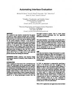
Fig. 7. Two possible test cases In order to be able to compare those two types of diagrams we will make use of a diagram mapping technology developed by [11] and [12]. Both have independently created technology for the purpose of transforming data between sequence diagrams and state diagrams, the former group also having built a support tool called SCED. Koskimies et al [11] claims that “the problem of synthesizing a state diagram on the basis of a set of scenario diagrams resembles the problem of learning a program from its sample traces.” This implies that a single scenario diagram (as depicted Fig. 4) would not represent a general ‘scenario’ (except maybe in the most trivial of cases). Thus, to make this problem more interesting (and useful) we need more scenarios to be able to validate our state diagram. For that purpose, Fig. 7 introduces an additional scenario (right side). Derived State Diagram using SCED do: create visiting record
[ patient found ] do: validate
do: get patient data
do: create patient
[ patient not found ]
Original State Diagram for Class Screen user input
create visiting record ID invalid
Enter pressed validate input
ID valid
check patient DB
Mismatch between state diagram and sequence diagrams can now be identified automatically
Fig. 8. Mismatches in the hospital system are now more obvious through usage of common base model.
Alexander Egyed 13
State diagrams for all involved classes may now be created by feeding above scenarios into a tool like SCED. The core of that tool consists of a state diagram synthesizer which can automatically create a state diagram reflecting the information of the individual scenarios. In case of the hospital scenarios above, the resulting state diagram may be seen in Fig. 8 (upper half). The lower half shows the original state diagram from Fig. 4. Like in the previous example, it is now possible to compare both views more easily because of the use of the same diagrammatic view. However, this example also shows that transforming information alone may not be sufficient in enabling automatic comparison. It would be hard to automatically identify mismatches simply because it is still unclear whether the boxes and arrows mean the same thing. For instance, both diagrams have four states. Thus, an automated tool could make the wrong assumption that user input corresponds to do:validate, validate input to do:get patient data and so forth. Thus, it may be necessary to manually adjust the mapping between views using the knowledge of the architects. Nevertheless, even without manual adjustment, automatic comparison of these views will identify potential mismatches. For instance, the original state diagram exhibits a feedback loop between the first two states which does not exist in the second one. Similarly, the derived state diagram has a shortcut from the second state to the last (forth) state which cannot be seen in the original one. Thus, the fact that these patterns in one view cannot be seen in the other view may already indicate potential mismatches. On the other hand, if say both state diagrams would exhibit the feedback loop then this pattern could be used to guess which model elements correspond to each other. Finally, there may be even other diagrams (not seen here) which, after being transformed, may shed additional light onto this situation.
5 Mapping and Differentiation The previous two examples showed cases of architectural mismatches between and within views. Basically, we distinguish between two dimensions of views – the vertical dimension (different view layers) and the horizontal dimension (different view types). View integration techniques must therefore also address both view dimensions. This paper showed one of each – Rose/Architect being an example for a vertical integration technique and SCED being one for horizontal integration. In a real development environment it is very likely that a combination of those techniques (and others) is necessary to yield effective results. For example, a state diagram may be derived using SCED but it must still be abstracted (simplified) in order to be comparable to the original state diagram (e.g. the create visiting record state in the original view could be broken down to do:create visiting record and do:create patient). Both Rose/Architect and SCED are also examples of the Transformation activity we presented in Fig. 1. The hospital system example also showed that the assumption of a common name base is not only unrealistic but actually impossible between some types of views. For instance, as it was mentioned before, the boxes and arrows in state diagrams are not semantically the same as the ones in sequences diagrams. Thus, it is clear that the
Alexander Egyed 14
names derived through transformation will most likely not match any other name. This is also true for the Rose/Architect model when it comes to the naming of transitive relationships. Therefore, when we talk about view integration we have to include other aspects then just the transformation of data. This was reflected in our integration framework in Fig. 1 which showed the Mapping activity as being another cornerstone for effective view integration. In order to deal with inconsistent naming of modeling elements some form of mapping activity is needed. In a simple case, mapping is done through some traces or name dictionaries. However, since both of those have to be done manually, they not only add an additional source of possible defects but also increase the manual overhead in applying integration techniques. The goal is therefore to have some automated mapping technology. The following information can be useful in identifying mapping. It is out of the scope of this paper to address the more automated aspects of mapping here. Please refer to [18] for more detail on that subject: •
•
•
Similar patterns: This type of mapping was indicated before when we talked about Fig. 8. There certain characteristics such as the feedback loop or the shortcut state transition can be used to identify mappings. In an ideal case, were the original view and the derived/abstracted view are consistent, both views should exhibit these patterns in the same sequence (not necessarily at the same place) regardless of what names are used. Common interfaces: In cases where some mapping for some components exist but not for others, the interconnectivity may be used to identify mappings. For instance, if there are two views with components A and B and both views are connected via differently named helper classes then it is possible that those helper classes are identical. Similarity in names: If we again use Fig. 8, we can see that, although, the names are not identical, they are nevertheless similar. Using the similarity of names is, therefore, another mapping technique.
Finally, to come back to Fig. 1, the third major activity of view analysis is Differentiation. There, the system model is traversed to identify (potential) mismatches within the system model. (Potential) mismatches are described in form of rules and constraints. Furthermore, mismatch resolution rules can be associated with the mismatch identification rules to propose options on how to resolve them.
6 Base Model and other Issues Having described techniques for mapping, transformation, and differentiation, it must be stressed that those techniques may not always yield correct results. As such, it could be that different interpretations of architectures are possible upon which either all are automatically investigated or a human being must be consulted to make a decision as to what is meant. Furthermore, no single technique will likely be sufficient. It
Alexander Egyed 15
is more likely that a combination of above techniques and others are necessary to yield a higher effectiveness. Scalability is yet another issue. The number of interactions and different interdependencies between model elements have non-linear side effects on many aspects of view integration. Currently we address scalability in two ways: 1) we employ a base model (Fig. 1) which reduces the scale of view integration considerably as mentioned before and 2) we validate new additions to the model right away. The latter point has the advantage that the amount of new information at any given time is reasonably small and that the existing information has already been validated before (not necessarily resolved). Thus, the effectiveness of view integration in addressing the issues above hinges strongly on the base model we discussed briefly in Fig. 1. Not only does the base model provide a view independent (ergo less redundant) representation, it is also critical for scalability. Furthermore, some integration activities like Differentiation depend on it to provide a common base for defining constraints and rules against which the modes/views can be validated. dependency
class
"Screen"
dependency
instance-of "validate"
Visiting Record
no name
class
instance-of
class "Patient"
calls no name
instance-of
calls
"patient not found"
condition 1
2
3
sequence D
no name
operator
calls
4 5
calls
"get patient data"
"create"
Fig. 9: Base Model Fig. 9 shows an example of a base model. It depicts the sequence diagram of Fig. 4 as well as a simple class diagram showing dependency relationships between Screen and Patient and Visiting Record. Further, the class Visiting Record has the operator create attached. The objects of the sequence diagram are instances of above classes. The dashed components and connectors in the figure indicate a potential mismatch between the class Patient and the sequence diagram call create because the latter uses a call to Patient which does not have an operator defined with that name. Other views can also be represented in this base model. The same applies to derived views using techniques such as Rose/Architect and SCED. Again we have to defer to [18] for more information about the base model.
Alexander Egyed 16
8 Related Work In one form or another, the view integration problem has been worked on by numerous researcher. This section discusses some of their works and also in what ways their works differ from ours. It is important to note that their view integration technologies are not independent or in any way orthogonal to ours. [Sage-Lynch 1998] wrote that “unfortunately, there appear to be no detailed definitions that distinguish between various types of integration, and this may appear to make the subject disjoint. [… However] integration is generally always being performed, but it is not clear as to where it is performed or how to accomplish it successfully.” This also means that integration is part of every aspect of the development life cycle and, thus, our work and the related work presented in this section, does somehow fit into the greater scheme of the view integration procedure: 1.
2.
3.
4.
5.
Gacek [13] addresses a very similar problem to ours – that of how to identify architectural mismatches. However, their work investigates mismatches on a rather high-level, that of software component composition. Components are defined through properties and potential mismatches can arise based on those properties. Garlan et al [14] provide an integration effort of numerous architectural description languages (ADLs). Usually, each ADL stands for itself (like views in UML) and in the context of this work can actually be seen as views. However, their work on an architectural interchange language called ACME has produced something else: an mechanism to share and exchange information between various ADLs. ACME itself does, however, not provide mechanisms for checking inconsistencies across various views. Finkelstein et al [15] base their work on the concept of ViewPoints which is similar to our views. Their work is very close to ours in that it presents some views and corresponding rules to identify inconsistencies within and between them. They further define a formal notation to represent those views. Even though their motivation and initial approach are very similar their focus their work on different life-cycle stages (e.g. requirements specifications). Wang et al [16] also acknowledge and address a deficiency of UML; the lack of precision and formalism. So they propose ways on how to eliminate that problem by presenting formal methods which they integrate with OMT. So they substitute Object Models with Algebraic Specifications, various OMT semantics with Algebraic semantics and Instance Diagrams with Algebra. However, they see the use of these formal extension less in automatic consistency checking but instead in combining the strength of both views – the readability of OMT with the precision of algebraic specifications. Grundy [17] addresses the integration problem by translating diagrams (views) onto a conceptual model (called the repository or base view). Overlaps between the design components are identified through the usage of common names. Their work is also rather high level and they do not address the problem of representing conceptually different views in their base model.
Alexander Egyed 17
The work presented above does not cover the complete picture of what is going on in this field. However, it gives an overview of the representative approaches. The diversity of the work above is another reason why this work thrives not to just add another technique. Many ideas described in their research are excellent and, thus, our work tries to also take the best of what already exists and build it into something bigger.
7 Conclusions As discussed previously, views are nothing more than an abstraction of relevant information from its model. Views are necessary to present that information in some meaningful way to a stakeholder (developer, architect, customer, etc.) – something the system model (Fig. 1) does not do. When we talk about the need for integrating views, we are really talking about the need of having a system model integrated with its views. Although, a full integration effort may seem impossible at this point, it can still be attempted for significant parts. With that purpose in mind, this work presented a framework and some techniques to help software developer in ensuring the conceptual integrity of their models, and thus ensuring the consistency of views. For a more detailed analysis of that problem please refer to [18]. Problems we have not yet fully addressed are: • • •
Finding (or developing) integration techniques covering a wide range of views Dealing with the state explosion problem in mapping and transforming views and as such with the issue of scalability Addressing the issue of automatically supported mismatch resolution (as compared to just automated mismatch identification)
Despite those problems, we feel that the potential benefits of using integration techniques, such as the ones above, are immense. We have shown that it is possible to (at least partially) automate the task of mismatch identification and since computers are clearly much more efficient in comparing views, this implies that substantial manual labor can be saved (currently, consistency checking is probably the largest development activity that is still done almost entirely manually). Another benefit of our approach is that mismatches may be identified as early on as they are created. Every time new data is added to the model, tools (e.g. agents) can validate them.
8 References 1. Booch, G., Jacobson, I., and Rumbaugh, J. (1997) “The Unified Modeling Language for Object-Oriented Development,” Documentation set, version 1.0, Rational Software Corporation. 2. Siegfried, S. (1996) “Understanding Object-Oriented Software Engineering,” IEEE Press.
Alexander Egyed 18
3. IEEE (1998) “Recommended Practice for Architectural Description,” Draft Std. P1471, IEEE. 4. Boehm, B., Egyed, A., Kwan, J., and Madachy, R. (1998), “Using the WinWin Spiral Model: A Case Study,” IEEE Computer, July, pp. 33-44. 5. AT&T (1993) “Best Current Practices: Software Architecture Validation,” AT&T, Murray Hill, NJ. 6. Sage, Andrew P., Lynch, Charles L. (1998) “Systems Integration and Architecting: An Overview of Principles, Practices, and Perspectives,” Systems Engineering, The Journal of the International Council on Systems Engineering, Wiley Publishers, Volume 1, Number 3, pp.176-226. 7. Rechtin, E. (1991) “System Architecting, Creating & Building Complex Systems,” Prentice Hall, Englewood Cliffs, NJ. 8. NASA (1993) “Software Formal Inspection Process Standard,” NASA-STD-220293. 9. Shaw, M. and Garlan, D. (1996) “Software Architecture: Perspectives on an Emerging Discipline,” Prentice Hall. 10. Egyed, A. and Kruchten, P. (1999) “Rose/Architect: a tool to visualize software nd architecture”, Proceedings of the 32 Annual Hawaii Conference on Systems Sciences. 11. Koskimies, K., Systä, T., Tuomi, J., and Männistö, T. (1998) “Automated Support for Modelling OO Software,” IEEE Software, January, pp. 87-94. 12. Khriss, I., Elkoutbi, M., and Keller, R. (1998) “Automating the Synthesis of UML Statechart Diagrams from Multiple Collaboration Diagrams,” Proceedings of the UML. 13. Gacek, C. (1998) “Detecting Architectural Mismatches During System Composition,” Doctoral Dissertation, Center for Software Engineering, University of Southern California, Los Angeles, CA 90089-0781, USA. 14. Garlan, D., Monroe, R.T., Wile, D. (1997) “ACME: An Architecture Description Interchange Language,” Proceedings of CASCON’97, November. 15. Finkelstein, A., Gabbay, D., Hunter, A., Kramer, J., and Nuseibeh, B. (1994) “Inconsistency Handling in Multi-Perspective Specifications,” IEEE Transactions on Software Engineering, August, pp. 569-578. 16. Wang, E.Y., Richter, H.A., and Cheng, B.H.C (1997) “Formalizing and Integrating the Dynamic Model within OMT,” Proceedings of the IEEE International Conference on Software Engineering, May. 17. Grundy, J.C., Hosking, J.G, Mugridge, W.B., Amor, R.W. (1996) “Support for Constructing Environments with Multiple Views,” Proceedings of the Viewpoint 96: International Workshop on Multiple Perspectives in Software Development. 18. Egyed, A. (1999) “Integrating Architectural Views in UML,” Technical Report, Center for Software Engineering, University of Southern California, Los Angeles, CA 90089-0781.