Traditional automation strategies are normally not applicable to small-batch ... selecting a satisfactory buffing path using commercial off-line programming.
AUTOMATING ROBOT PROGRAMMING IN THE CLEANING AND DEBURRING WORKSTATION OF THE AMRF Frederick M. Proctor, Karl N. Murphy, and Richard J. Norcross Robot Systems Division, National Institute of Standards and Technology
ABSTRACT In the Cleaning and Deburring Workstation, two robots cooperate to accomplish deburring, buffing, cleaning, and handling of machined metal parts. A technique has been developed which uses part geometry data to generate robot paths automatically. Using a graphics interface, an operator specifies how a part is to be gripped, fixtured, deburred, buffed, and cleaned. A path planner combines this process plan with geometry data to compute robot paths. A workstation controller coordinates the actions of both robots, allowing various steps in the finishing process to be performed simultaneously. This paper describes the methods used to automate the finishing process.
INTRODUCTION The Automated Manufacturing Research Facility (AMRF) of the National Institute of Standards and Technology (formerly NBS) is a research testbed consisting of three machining workstations, an inspection workstation, a distributed material handling workstation, and a cleaning and deburring workstation [1]. Initiated in the early 1980s with funds from the Manufacturing Technologies Program of the U.S. Navy, the AMRF serves as a vehicle for the development and testing of techniques to automate small-batch manufacturing. Traditional automation strategies are normally not applicable to small-batch manufacturing. The lot sizes are small, and the inventory of part types large, so machinery dedicated to the performance of single part-dependent tasks is not cost-effective. Equipment that can fulfill diverse roles without human intervention is necessary for the effective automation of a smallbatch factory. This type of flexibility is provided by robots, which can be programmed to perform a variety of tasks automatically. The AMRF has been partitioned into workstations dedicated to performing some particular duty. One or more robots serve each workstation, programmed to position and process parts depending upon the part geometry. This allows for a large number of different parts to be processed by the same equipment without manual assistance. The Cleaning and Deburring Workstation The Cleaning and Deburring Workstation (CDWS ) has been assigned the task of finishing the parts machined at the other workstations. Finishing processes include deburring of edges with rotary tools, buffing with cloth wheels, brushing with wire or abrasive wheels, and washing. The research effort began in 1985 [2], with research evolving from deburring to automating robot programming. _____________________________________________________________________________ This work was partially funded by the U.S. Navy MANTECH Program. This paper was prepared by U.S. Government employees and is not subject to copyright. Equipment listings do not imply a recommendation by NIST, nor do they imply that the equipment is necessarily best for the purpose.
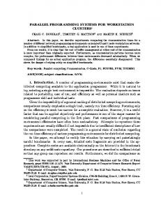
Equipment in the CDWS consists of two cooperating robots with a rotary vise for part fixturing placed in their common volume, tray stations for part transfers in and out of the workstation, a four-head buffing jack, and a washer/dryer system. A Unimate 2000 six-axis hydraulic robot is equipped with a gripper for part handling and buffing. A PUMA 760 six-axis electric robot is fitted with a quick change wrist which allows for selection between various deburring tools and a gripper. Both the 2000 and the 760 participate in part handling. Deburring is assigned to the 760, while buffing and tray transfers are assigned to the 2000. An overhead view of the workstation layout is shown in figure 1.
Dust Collector
Washer-Dryer System
Water Tank & Air Heater
Buffing Wheels
Rotary Index Table
Unimate 2000 Robot
Puma 760 Robot
Vise
Tool Rack Tray Station #2
Tray Station #1
Scale 0
5 ft
Figure 1. Workstation Layout. Process planning and task scheduling are undertaken by the Workstation Controller (WSC) [3]. The WSC is a set of software modules running on a SUN computer. The WSC provides an interface to the AMRF cell and database, a graphic interface for user selection of finishing processes and parameters, a scheduler which allocates tasks at runtime, and interfaces to the equipment level.
A typical operational scenario of the CDWS is as follows: 1.
The process plan for finishing is developed by a user at a graphics interface. This includes selecting edges to be deburred and the tools, tool speeds and feed rates desired; specifying the gripping and vise fixturing required for part handling; and selecting a satisfactory buffing path using commercial off-line programming software.
2.
Parts machined at other workstations are delivered to the incoming tray station by an automated guided vehicle.
3.
The deburring, buffing, and part handling paths are downloaded to the robots.
4.
The 2000 removes a part from the tray. If the part is to be deburred, the 2000 places it into the rotary vise, and the 760 begins the deburring process.
5.
If the part is to be buffed, the 2000 performs any necessary part reorientation to access the face to be buffed and brings the part to the buffing wheels.
6.
Typically, several parts are processed concurrently.
7.
Any refixturing of the part required for deburring or buffing is performed at the rotary vise as soon as a robot becomes available.
8.
Parts requiring cleaning are taken to the washer/dryer. Hot water sprays remove cutting fluids and buffing compound, and hot air dries the parts.
9.
The finished parts are oriented if necessary and placed into the outgoing tray station, where an automated guided vehicle removes them.
The workstation controller schedules the activities during the operations to ensure efficient processing of the parts. Automating Robot Programming The ability of robots to work continuously suits them to high-production applications, while the precision to which they can retrace their motions suits them to processes that have stringent requirements for reproducible results. Furthermore, their ability to be programmed for different tasks has allowed automation in cases where dedicated machinery would not be cost-effective. In many cases, however, the time and effort required to program robots for different processes more than offsets the advantages gained by automating. The National Institute of Standards and Technology has chosen to tackle this problem by researching methods to generate the sequences of robot motions required for part finishing automatically. Robots in industry are usually programmed by teaching, a process that is tedious and timeconsuming. During teaching, an operator brings the robot to each desired location (or point) with a joystick or teach pendant, and stores the coordinates of the point. Later, a program is written that will step the robot through the sequence of taught points. Unfortunately, teach programming is time-consuming and requires that the robot be brought off the production line for teaching. An alternative approach is to compute the desired robot coordinates instead of teaching them. This procedure requires that the location of the desired points be computed relative to the robot's coordinate frame. Once the points are computed, they are simply downloaded to the robot, which then steps through them in sequence.
The problem with using computed points is that robots are inherently inaccurate. Although most robots are highly repeatable, which means that they can consistently return to a previouslytaught point, the accuracy to which they attain computed points is much lower. For example, the repeatability of the 760 is 0.008 inches, while its accuracy is on the order of one inch. A major source of inaccuracy is the discrepancy between the kinematic model and the actual robot. The kinematic model is the physical description of the robot, and is used to transform the Cartesian coordinates of the end-effector to joint angles. In practice, the parameters of the kinematic model do not match those of the robot due to the limitation of manufacturing tolerances when the robot was fabricated, so the joint angles computed with the model will not result in the specified Cartesian location. Part misplacement in the trays, tool wear, and deformation of the robot under load or temperature changes also contribute to the overall inaccuracy. If computed points are to be used, there must exist some method for correcting the inaccuracies of the robot to the degree required by the application. Many methods have been developed to correct robot kinematic errors. Sensor feedback from a vision system or laser tracker can be used to determine the errors and compensation needed. Force or interference feedback can be used to signal that the robot is in contact with a part or fixture, indicating that is has reached its goal. Also, an error map can be constructed empirically, resulting in a table of errors for given coordinates. When the robot is told to move to specific coordinates, the error table is consulted and the coordinates are scaled by the appropriate amount so that the resultant motion will be more accurate. APPLICATIONS Advances in automating robot programming have been applied to four processes in the CDWS : part handling, deburring, buffing, and cleaning. This programming employs a combination of off-line programming techniques with run-time corrections. Part Handling Part handling occurs in three areas of the workstation: at the tray stations, the rotary vise, and the washer/dryer. Both the 2000 and the 760 can reach the vise and washer/dryer, but only the 2000 can reach the tray stations. Part handling at the tray stations and washer/dryer is a single pick-and-place operation, so programming robot paths at these locations is straightforward. At the rotary vise, however, the part must be rotated, flipped, regripped, and refixtured to allow for the deburring of all edges. Determining the proper sequence of pick-and-place motions that will bring the part from one orientation to another is more complicated. Geometry data is used by the graphics interface to present a picture of the part to a user, who selects vise clamp and robot grip locations (figures 2 and 3). These locations must be judiciously chosen so that there exists a series of points attainable by the robot that brings the part from its initial to its final position. Once this set of points is selected, a node matrix is automatically constructed from pairs of grip and clamp points (figure 4). A valid node is a pair of grip and clamp points where the gripper does not hit the vise and the robot does not exceed its joint limits. Adjacent entries in the node matrix share the same grip or clamp point. Once the nodes have been determined, the matrix is traversed automatically to find the shortest path from the initial to final part position (figure 5). The nodes are transformed into robot grip locations and then downloaded.
(A)
(B)
(C)
Figure 2. Vise Clamp Selection. An operator specifies how a part is to be fixtured in the vise. The initial placement is at (A). (B) represents an intermediate location, while (C) is the desired final location. Necessary intermediate locations must be determined by the operator in cases where the part cannot be fixtured in a single pickand-place operation.
(a)
(b)
Figure 3. Robot Grip Selection. An operator specifies how a part is to be gripped during the part fixturing. (a) represents a grip from the top, while (b) represents a grip from the side.
Grip (a) (b) (A) Clamp (B) (C)
Node – Node Node – Node
Figure 4. Develop Node Matrix. The matrix has valid nodes at locations where the robot and the vise can hold the part simultaneously. Nodes do not exist where joint limits or collisions are detected.
(A-a)
(B-a)
(B-b)
(C-b)
Figure 5. Traverse Node Matrix. The shortest path that will bring the part from its initial vise location (A) to its final vise location (C) is determined. The path must consist of adjacent nodes. If no path exists, additional intermediate clamping or gripping locations must be selected. Robot positioning inaccuracies are corrected using an error map. Since all downloaded positions are relative to the vise origin, locations of the vise origin that would result in accurate placement for various tool orientations have been taught. The downloaded offsets are then assigned an appropriate origin at runtime, compensating for errors that arise from orientation changes. Error maps are also used to correct translational motions. Actual motions of 115 mm have been observed for commanded motions of 100 mm. To account for this, commanded motions are scaled using a table of empirically-determined scale factors. Deburring Edge deburring is accomplished by tracing part edges with various pneumatic deburring tools. An end brush fitted with abrasive-loaded monofilament bristles is used on most edges, while a countersink tool and hole brush are used for hole deburring operations. Programming consists of three steps: data preparation, pose computation, and path correction [4]. During data preparation, the geometry description and the process plan for the workpiece are developed by a user off-line. Pose computation takes the geometry description and the process plan and produces a robot trajectory file. A pose is the robot's position and orientation; the trajectory file describes the sequences of poses the robot must follow to deburr the selected edges of a workpiece. Path correction is performed using a force sensing technique to compensate for robot kinematic errors, tool wear, and minor part misplacement. These three steps generate usable robot deburring trajectories for prismatic workpieces in about two hours with minimal manual input. Data Preparation Both part geometry data and a process plan are required for deburring. The geometry data represents the edges of the workpiece as the intersection of two surfaces. The process plan associates groups of edges with the tools, speeds and feed rates used to deburr those edges. This data is commonly produced long before the actual deburring process, often before the first workpiece is machined. The geometry file can be derived directly from the AMRF Geometry Modeling System (GMS ) [5], or may be created manually with a text editor. The process plan file is generated through a graphics interface provided at the workstation. The graphics interface displays the workpiece
and a number of buttons and scales. An operator chooses which edges to deburr by clicking a mouse pointing device on the edges. The operator uses the buttons and scales to select the part orientation, the deburring tool, the tool's parameters, and the order of operations (a sample display is shown in figure 6). Once created, the information is stored in the database for subsequent use in the creation of the deburring trajectories and for scheduling tasks. CDWS Graphics Edge Selection QUIT
DRAW SAVE
VIEW:
TOP bottom left right front back
TOOL: END BRUSH
RATE
SPEED
OFFnormal
FORCE
OFFcenter
counter sink 5/8 hole br.
0.58
9000
7.6
10.0
0.00
(ips)
(RPM)
(deg)
(oz)
(in)
Figure 6. Graphic Edge Selection. An operator selects the side of the part to be viewed, the deburring tool to be used, and the tool parameters such as feed rate, speed, and force. A mouse pointing device aids in the selection. Pose Computation Pose computation is the translation of the process plan into a set of robot trajectories. Each trajectory specifies the poses the robot must attain to approach, deburr, and depart from a set of edges. In addition to the the process plan and the part description, the pose computation requires knowledge of the configuration of the workcell, limitations of the deburring robot, and the proper use of the deburring tool. The translation from the process plan to robot trajectories takes several steps. Connecting edges are first grouped into loops. A tool orientation is then selected for each edge in the loop based on the surfaces which create the edge and the reach limitations of the deburring robot. If a collision between the tool and other edges is detected, the edge is divided and new tool orientations are chosen to avoid the collision. Approach poses, depart poses, tool-on and tooloff commands are then added to the loop to form a complete trajectory. Finally, the trajectory information is formatted and downloaded to the robot. Force Correction To compensate for kinematic error, part misplacement, and other system inaccuracies, computed points are corrected at run-time using force feedback, as shown in figure 7. After the first part is
fixtured, the robot approaches each end point of the deburring paths half an inch back along the Z axis (i), and drives the tool forward while reading a wrist force sensor until a desired contact force is met (ii). The coordinates of these points replace the previous points (iii). When all points on the paths have been corrected for inaccuracy, the paths are traced with the tool running to accomplish deburring. This process is repeated for approximately every tenth part to account for tool wear.
X
Z
F
(i)
(ii)
(iii)
Figure 7. Pose Correction using Force Feedback. The computed poses are not correct due to system inaccuracies. To correct a pose, the robot starts back from the initial point (i), moves in until the commanded force is obtained (ii), and records the new point (iii). When each pose is corrected, the path is used to deburr all parts of that type. To account for tool wear, the poses are corrected again after a period determined by the workstation controller. Buffing The CDWS is capable of buffing with cloth wheels using liquid buffing compound, and brushing with wire or abrasive-loaded monofilament wheels. The speed at which the wheels rotate is selectable, as is the force with which the part is placed against the wheels. Commercial off-line programming software automates the generation of the robotic buffing trajectories. The software consists of a generator which computes paths and a simulator which displays the computed robot motion. Using this software, an operator selects points on a computer model of the workpiece. These points define a path which will pass across the surface of the buffing wheel. Approach and departure points are also specified. Using the part model and the gripping data, the simulator displays an animation of the robot gripping the workpiece. Then, based on the kinematics of the robot, the animated part is run against a simulated buffing wheel. The face is divided into small sections, and a routine determines the time each section spends in contact with the wheel. An operator views a graphic representation of this data to determine if the buffing is being performed evenly across the work face and if the duration is proper for the desired finish. If coverage is not adequate, the operator modifies the path and repeats the simulation. Once a satisfactory path has been generated, the points and the type of wheel to be used are downloaded to the robot. The 2000 uses a force sensor to position the workpiece against the wheels with the proper force for adequate buffing. In a procedure similar to that used for deburring, the robot approaches the first computed point at the spinning wheel with the part held face out, and moves slowly forward until the desired force is achieved. The difference between this point and the computed point is used to correct the remaining points on the path. This correction is necessary to ensure that the
part is buffed with the proper interference. Since satisfactory buffing depends not only on the time a part is placed against the wheels, current efforts in automating buffing trajectories include integrating the relative angles between the wheel and workpiece, and developing force and torque values to allow programming based on forces in addition to positions. Cleaning Cleaning usually occurs directly after buffing in order to remove buffing compound. The part is placed onto a rotary table and indexed into the washer, where hot water sprays remove cutting fluids and buffing compound. The part is then indexed into the dryer, where hot air removes surface water. After the cleaning has been completed, the part is indexed out and retrieved by either robot, to be returned to one of the tray stations. The WSC is responsible for issuing index, wash and dry commands to the equipment controller after the part has been placed for cleaning. When the cleaning cycle is finished, an available robot is commanded to remove the part. SCHEDULING AND CONTROL Control of the workstation is divided hierarchically as shown in figure 8. The WSC receives commands from the operator or from higher control levels in the AMRF. These commands are decomposed into lower-level commands for the two robot controllers, which in turn are decomposed into commands for the equipment controllers. AMRF
Local Operator
Workstation Controller
Unimate 2000 VAL-II
PUMA 760 RCS
Vise
Tools
Quick Change
Robot
Rotary Vise
Gripper
Robot
Robots
Buffing Wheels
Washer Dryer
Equipment Controllers
Buffing Wheels
Washer Dryer
Equipment
Figure 8. Workstation Control Structure. The bottom layer represents equipment that is controlled by the higher layers. Workstation Controller The workstation controller coordinates the activities of the robots and equipment at the workstation and was developed to control multiple simultaneous and independent tasks [6]. The WSC decomposes tasks into a series of lower-level tasks. Each task requires a set of resources, such as a particular robot or the vise, and a set of prerequisite tasks, such as part placement in
the vise before deburring. When a task acquires a resource it prevents other tasks from utilizing it. This resource assignment occurs at the lowest level of the task decomposition as possible so that resources are acquired only when they are immediately needed and released as soon as they are no longer required. Tasks are dispatched to the equipment-level controllers in a method known as Opportunistic Scheduling [7]. With this method, tasks are executed as soon as their prerequisites are completed and their required resources become available. When several tasks that share a common resource are able to execute at the same time, the first task scheduled is the one that would release the common resource earliest. Where the workstation has redundant capabilities (e.g., part handling), the workstation controller has established preferences. The workstation controller can also generate commands for the equipment-level controllers in anticipation of completed prerequisites. All of these features are intended to enhance the workstation's flexibility and efficiency. At the Cleaning and Deburring Workstation, the equipment-level controllers are highly integrated with sensors. Thus, although the nominal execution times for tasks are known, the time required to complete any given task is not known with certainty. Opportunistic Scheduling is a type of dispatching intended to improve system performance when the occurrence of a prerequisite event is not predictable. The method collects tasks which would be executable upon the availability of a resource, such as a robot or other piece of equipment. As the resources are freed, the newly permitted tasks can be dispatched according to additional rules. An additional priority rule at the CDWS is Shortest Immediate Job First . That is, the task which requires a resource for the shortest time is given the resource first. When a task requires a resource, it acquires that resource and prevents other tasks from utilizing it. Since most tasks are prerequisites to other tasks, performing the shortest task first reduces the chances that future tasks will be needlessly blocked. For example, since part movement is a relatively short prerequisite to another function and buffing can take several minutes, part movement occurs before buffing. Because part handling is common to all finishing processes, both of the robots can perform part handling. This redundancy reduces the system's idle time but adds to the system's complexity. Scheduling the redundancy consists of establishing preferences between the robots. If both robots are able to perform the same part transfer, the most preferred robot is chosen. Occasionally, a task that requires some preparation is prevented from executing due to a busy resource. To allow preparations that should not be blocked by the busy resource to proceed, the WSC is designed to generate and use predictive commands. These commands are issued before the busy resource has been freed to allow time for the preparation. If the resource is still in use after the preparations have been completed, the task will be prevented from proceeding by the lockout protocols described in the Equipment Control section below. If the resource has been freed during the preparation, the task will proceed without delay. Robot Interfaces PUMA 760 The PUMA 760 robot is controlled by the NBS-developed Real-time Control System (RCS) which consists of a database and five hierarchical control levels [8]. The RCS communicates with the WSC over three serial lines; one each for data, commands, and status. The RCS sends joint angle commands to the 760's joint servo cards over a serial link following the Unimation-developed Slave Protocol [9]. Parallel data lines drive pneumatic valves for tool and quick-change
operation. Vise volume requests and vise commands are sent to the equipment controller according to the lockout protocol explained in the Equipment Controller section below. The RCS monitors a wrist-mounted force sensor during the self-teaching operations for deburring and for unexpected collisions. Switches used during quick changes of end-effectors ensure proper seating, release, and tool type. The five control levels, Task, Path, Prim, Joint, and Servo, form a control hierarchy. The WSC sends movement and deburring commands to the Task level. For each command, Task determines whether to change end-effectors, when to move or deburr the part, and how to move between the vise, the washer/dryer, and the quick change rack. To move, change tools, or deburr, Task sends a path, a list of instructions, to the Path level. A path exists for all robot activities. Frequently used paths, such as those which change tools or move the robot about the workstation, are generated manually. Part handling paths are hybrids in which grip locations are generated automatically, as described above in the Part Handling section, but the motions relative to the grip locations are developed manually. In contrast, all deburring paths are computed automatically from geometry data and a process plan, as described in the Deburring section. When the Path level receives a new path, it executes the list of instructions in sequence. Each instruction represents an operation, such as turning the tool on, opening the vise, or moving the robot to an intermediate location. The intermediate motions result in the sending of goal poses to the Prim level. When Prim receives a goal pose, it calculates the sequence of poses needed to bring the robot to the goal and sends them to the Joint level, one pose every 28 msec. The Joint level converts the poses to joint angles which are sent to the 760's joint servo boards. Unimate 2000 The Unimate 2000 robot is controlled by the vendor-supplied controller, VAL-II. The robot controller communicates serially with the WSC according to a locally-developed protocol. The protocol provides for the sending of commands from the WSC to the robot controller and the relaying of status from the robot to the WSC. The robot controller sends vise actuation, buffing wheel, and lockout protocol commands to the equipment controllers over parallel data lines. Status from the equipment controllers is relayed through additional parallel data lines. Force threshold data is available to the robot controller. Two threshold levels are selectable, one for part handling and one for buffing. The first threshold is a maximum which signifies that a part is being placed improperly. The robot is instructed to depart, signaling the error to the WSC. The second force threshold is a minimum that must be attained for satisfactory buffing. As a safety measure, a third maximum threshold has been established so that damage to the robot or equipment can be avoided. This safety thresholding operates continuously. Although the part handling and buffing locations are generated from CAD data, the programs that step the robot through these locations have been written manually. These programs use the grip locations developed with the graphics interface and the buffing paths developed with the off-line programming software, allowing for a wide range of part types and scheduling conditions. Equipment Control The rotary vise, washer/dryer, and buffing wheels are controlled by dedicated computers which accept commands from both robots and the WSC . The WSC commands the washer/dryer to index the rotary table, spray hot water for washing, and blow hot air for drying. The 2000 sends speed commands to the buffing wheels and spray commands to the compound sprayers. Both robots
can open, close, or rotate the vise; commands from only one robot are accepted at a time. The equipment controllers decompose the commands to low-level signals used to drive the equipment. Equipment status is input by the controllers, formatted, and relayed to the command source. The equipment controllers also enforce lockout protocols in cases where collisions are possible. In order to prevent collisions, a request must be made to the equipment controllers for access to one of the resources. If the resource is free, the request is granted and access is allowed. If the resource is busy, the request is denied. The request is usually maintained until it is granted, but it may be rescinded. Collisions between the two robots can occur at the vise, which requires that both robots make requests for the vise volume. In addition to allowing access, however, a grant carries with it the privilege of actuating the vise. To prevent the AGV from moving a tray while the 2000 is gripping a part in that tray, the AGV and the 2000 must make requests for tray station access. The tray station lockout protocol serves to prevent accidental collisions, as well as prohibiting the AGV from removing unfinished workpieces. Collisions can also occur at the washer/dryer involving the rotating table and a robot. Since the issues index commands, a lockout exists between the WSC and the robots. A grant to the prevents the robots from entering the volume, while grants to the robots prohibit the WSC from indexing the table.
WSC WSC
SUMMARY A robotic cleaning and deburring workstation provides improved flexibility over dedicated automation, and greater repeatability than manual methods. However, in cases where a wide variety of parts are produced in small numbers, these advantages are offset by the labor required to accurately program the robot for each part. Researchers at the National Institute of Standards and Technology are developing techniques which significantly reduce the manual programming requirements for finishing applications. A graphic interface allows an operator to quickly associate features of a part with various finishing processes and to specify the speeds, feed rates and contact forces desired. The operator can also specify gripping and clamping locations for proper fixturing of the part. The resulting process and fixturing data are combined with geometry data to automatically generate robot paths. A workstation controller schedules the actions of the robots to accomplish several finishing tasks simultaneously. Errors in robot kinematics, minor part misplacement, and tool wear are corrected by each robot using combinations of error mapping and force feedback. This approach has proven effective for deburring and buffing aluminum and brass parts. REFERENCES 1. J. Simpson, R. Hocken, and J. Albus, "The Automated Manufacturing Research Facility of the National Bureau of Standards", Journal of Manufacturing Systems 1 (1) (1983). 2. H. McCain, R. Kilmer, and K. Murphy, "Development of a Cleaning and Deburring Workstation for the AMRF", Proceedings of Deburring and Surface Conditioning '85, Chicago, IL (September 1985). 3. R. Norcross, "Cleaning and Deburring Workstation Controller User's Reference Manual", to be published as a National Institute of Standards and Technology Internal Report. 4. K. Murphy, R. Norcross, and F. Proctor, "CAD Directed Robotic Deburring", Proceedings of the Second International Symposium on Robotics and Manufacturing Research, Education,
and Applications, Albuquerque, NM (November 1988). 5. T. Hopp, "AMRF Database Report Format: Part Model", National Bureau of Standards Internal Report 87-3672 (September 30, 1987). 6. R. Norcross, "A Control Structure for Multi-Tasking Workstations", Proceedings of the 1988 IEEE International Conference on Robotics and Automation, Philadelphia, PA (April 1988). 7. B. R. Fox and K. G. Kempf, "Reasoning about Opportunistic Scheduling", Proceedings of the 1987 IEEE International Conference on Robotics and Automation, Raleigh, NC (March 1987). 8. S. Leake and R. Kilmer, "The NBS Real-time Control System User's Reference Manual", NBS Technical Note 1250 (August 1988). 9. "SLAVE Interface Specification for External Computer Path Control Using VAL-II", Publication Number 397T1, Unimation Inc., Danbury, CT (January 1986).
Presented at Deburring and Surface Conditioning ’89, February 13-16, 1989, San Diego, CA. Catalogued as Society of Manufacturing Engineers Technical Paper MR89-138.