Globecom 2012 - Ad Hoc and Sensor Networking Symposium
Autonomous Recovery from Multi-node Failure in Wireless Sensor Network Yatish K. Joshi and Mohamed Younis Dept. of Computer Science and Electrical Engineering University of Maryland Baltimore County Baltimore, MD 21250 yjoshi1,
[email protected] This paper proposes an effective recovery solution to Autonomously Repair (AuR) damaged WSN topologies. AuR is a distributed approach that exploits node mobility to restore strong connectivity in the network by moving disjoint blocks of nodes towards one another and towards the center of the deployment area. The design principle of AuR is based on modeling connectivity between neighboring nodes as a modified electrostatic interaction based on Coulomb’s law between charges. The neighbors of failed nodes lead the recovery process by spreading out in the deployment area to find other nodes and by pulling their blocks towards the center of the area. The recovery is localized with nodes interacting only with their immediate neighbors. The performance of AuR is validated through simulations and shown to be effective in reconnecting all nodes, mitigating some of the lost coverage. The paper is organized as follows. The next section sets AuR apart from existing recovery solutions in the literature. Section III discusses the assumed system model. AuR is described in detail in Section IV. Section V reports the simulation results. Finally, Section VI concludes the paper.
Abstract— Wireless Sensor Networks (WSNs) often serve mission-critical applications in inhospitable environments such as battlefield and territorial borders. Inter-node communication is essential for WSNs to effectively fulfill their tasks. In hostile setups, the WSN may be subject to damage that breaks the network connectivity and disrupts the application. The network must be able to recover from the failure and restore connectivity so that the designated tasks can be carried out. Given the unattended operation of the network, the recovery should be performed autonomously. In this paper we present a distributed algorithm for Autonomous Repair (AuR) of damaged WSN topologies in the event of multiple node failures. AuR models connectivity between neighboring nodes as electrostatic interaction between charges based on Coulomb’s law. The recovery process is initiated locally at the neighbors of failed nodes by moving in the direction of loss to reconnect with other nodes. The performance of AuR is validated through simulation. Keywords: Topology repair, Fault recovery, Connectivity restoration, Fault-tolerance, Wireless sensor networks.
I.
INTRODUCTION
WSNs are very effective in harsh terrains where humans cannot venture like deserts, sea beds, etc. Applications include battlefield reconnaissance, border protection, wildlife and environment monitoring, space exploration and security surveillance [1]. In many of these applications nodes are randomly deployed to form a network in an ad-hoc manner. During normal operation, nodes share their findings and coordinate amongst themselves to achieve application goals. Therefore, inter-node connectivity is very important for the operation of a WSN. The loss of connectivity due to single or multiple node failures can partition a WSN into disjoint segments, which limits its ability to function effectively. Node failures can occur due to limited battery life, harsh operating conditions or due to hostile action, e.g., sabotage. Since WSNs operate independently and unattended, they should have the ability to self-heal from failure. Careful node placement during network setup and resource management can help in achieving strong network connectivity and prolong network lifetime [2-4]. In addition, deployment of redundant nodes can mitigate a failure by providing spares [5]. However, these approaches cannot recover the network if only random placement is feasible e.g., dropping nodes from a helicopter. Provisioning redundancy may also not be sufficient to recover from multiple failures which fragment the network into disjoint blocks. A number of approaches have been proposed to overcome single node failures by replacing the failed node and using cascaded repositioning of nodes to re-establish strong network connectivity [6], or by having the neighbors move towards the failed node until they are reconnected [7]. However, these approaches cannot handle multiple failures.
II.
RELATED WORK
A number of approaches have been recently proposed for autonomously restoring connectivity after the failure of a critical node [6-9]. The idea is for the neighbors of a failed node to collaboratively decide on how to bridge the gap that a loss introduces by moving one or multiple healthy nodes. The scope of neighbor involvement in relocation varies depending on the pre-failure network state that a node maintains. DARA [6] and PADRA [8] rely on a node’s awareness of its 2-hop neighbors so that a failed node is replaced with one of its directly reachable nodes. Meanwhile, RIM [7] assumes that a node knows only its 1-hop neighbors, thus more nodes would be required to move. However, these approaches cannot handle multi-node failures since the nearest live node may be many hops away and not a member of the 1-hop or 2-hop neighbor lists maintained by surviving nodes. This can be resolved by a neighbor list comprising of many hops which imposes major overhead and makes the recovery process more complex, approximating a centralized approach where each node ends up with information about all nodes in the network. Distributed approaches for recovery from multi-node failures, like DORMS [10], use mobile relays. The idea is to move some of the surviving nodes towards the center of the deployment area along the shortest path and forming an intersegment topology. The grouping of connected surviving nodes into a segment is almost like a centralized process but on a smaller scale as all nodes in a segment act collectively for recovery purposes. AuR on the other hand is truly local; each node is allowed to consult only with its 1-hop neighbors.
670
Connectivity restoration work in the literature can be further categorized according to the pattern of motion. Some techniques have pursued cascaded node relocation to ensure that the network stays connected during and after recovery [7][8][9][10]. Block motion has also been proposed. For example, Basu and Redi [11] aim to restore bi-connectivity in the network after a node fails by moving a subset of nodes as a group. Sustaining bi-connectivity makes the recovery much easier since coordination amongst healthy nodes is not affected by the failure. In addition, it imposes significant prefailure overhead and constrains the movement of nodes during normal network operation. Therefore this category of approaches is not practical for multi-node failure scenarios. Modeling node movement based on electrostatic forces has been pursued in other published work, e.g., C2AP [4], VEC [12] and DSSA [13]. However in AuR each node experiences an electrostatic force of attraction or repulsion depending on the situation, whereas C2AP uses only repulsion to maximize coverage. In addition, modeling of forces in AuR is different from DSSA. We try to mimic molecular attraction and repulsion closely so that each node maps out a virtual path based on the forces acting on it and keeps moving until the effect of forces diminishes, i.e., reaching equilibrium, while keeping connectivity restriction in mind. In [13] the forces depend not only on the distance between nodes but also on local node density. VEC [12] also uses Coulomb’s law wherein a node is repelled towards the uncovered part of its voronoi polygon by the repulsive force acting on it due to its neighbors and the vertices of the polygon. Lastly C2AP, DSSA and VEC opt to improve coverage and do not handle network partitioning caused by multiple node failures. Finally, repositioning of mobile sensors via cascaded movement is used in [5] to recover from a failure. Redundant nodes are identified in different parts of the network and cascaded motion takes place in conjunction with intermediate nodes along the path. The goal is to mitigate the coverage loss. AuR does not rely on the availability of redundant nodes. In addition, the approach of [5] is based on node density and does not care for connectivity. III.
with connectivity restoration after the failure of one critical node like S9 and S12, as pointed out in the previous section. On the other hand, multi-node failures pose unique challenges since the extent of failure can be vast and surviving nodes do not know the location of other live nodes. Therefore a strategy has to be devised to ensure that nodes in disparate locations can be mobilized and reconnected. In a centralized approach the general area can be mapped and the surviving nodes can communicate via satellite to determine the location of other live nodes and chart a re-connectivity strategy based on the current location of all nodes. This though has considerable messaging and resource overhead to keep the relocation in sync. In addition, availability of satellite links cannot be guaranteed due to line of sight issues or simply because nodes do not have modems or sufficient power.
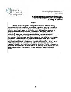
Figure 1: An example connected network topology.
IV.
RESTORING CONNECTIVITY USING AUR
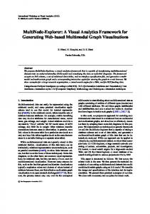
A. Overview of the Recovery Approach If a network gets partitioned due to the failure of a group of nodes, each neighbor SN of these nodes will apply AuR. Obviously, these nodes will be on the periphery of their partition. Thus, these periphery nodes in each partition will apply AuR and move outward, and other nodes within the partition follow.. The collective effect resembles stretching the intra-partition topology towards the failed nodes, as shown in Figure 2. Then, SN will discover that it could not connect with its former 1-hop neighbors and apply AuR again. When the topology cannot stretch any further, the nodes will move towards the center of the area. Since AuR will be concurrently applied by all partitions, the partitions gradually move inward until they connect with another partition or reach the center of the deployment area. Once a partition reaches the center or when it reconnects with another partition connected to the center a final self-spreading is done to maximize coverage. It is worth noting that the area covered by the federated network formed by AuR would most probably be larger than the
SYSTEM AND PROBLEM MODELS
The proposed AuR approach can be applied to networks that include mobile sensor nodes. We assume that each mobile node is aware of the size and center of the deployment area and its position, e.g., using contemporary localization schemes [14]. All nodes are assumed to have the same transmission range that is significantly less than the size of the deployment area. Node failure may result in a loss of connectivity and coverage. AuR focuses on re-establishing connectivity and as a secondary objective tries to restore some of the lost coverage through optimized node self-spreading. Node failures impact a network in different ways depending on their importance to network connectivity and the scope and scale of failure. The loss of a leaf node does not affect connectivity, though failure of a cut-vertex or multiple collocated nodes will split the network into multiple disjoint segments and undermine the network operation. In Figure 1 the loss of leaf nodes, e.g., S3, S4 or S16 does not impact the network connectivity. The same applies for some non-leaf nodes, namely, S12 and S14, as alternate paths exist among neighboring nodes. Failure of S1 or S9 however results in two or more disjoint blocks. Numerous published approaches deal
Partition#3
Partition#1
Partition#1
Partition#3
Partition #4
Partition#4 Partition#2
Partition#2 : Sensor
: Sensor
(a) (b) Figure 2: Illustration of how AuR restores connectivity in a partitioned network (a) by spreading nodes within the individual blocks towards the unreachable parts of the network and then moving them towards the center of the deployment area.
671
combined regions covered by the individual partitions. This can be attributed to the fact that AuR opts to minimize the travel distance by self-spreading before and at the end of the recovery process. Thus, the topology is stretched and the coverage overlap among the nodes is decreased. We definitely acknowledge that AuR may restore coverage in the inner part of the network at the expense of the outer part. However, AuR maximizes the coverage given the available set of nodes.
degree ‘β’. A higher ‘β’ means higher priority. The rationale is that nodes with higher ‘β’ will drag many neighbors behind them and increase the level of self-spreading and consequently expediting the recovery. iii. Node ID: If two nodes have the same P or β, the node with the lower ID moves first. The network depicted in Figure 3(a) experiences simultaneous failures of nodes S0, S5, S6 and S7. S1 has a lost node degree of two (P=2) as it was in direct contact with the failed nodes S6 and S7, while its neighbor S9 has a lost node degree of one (P=1) due to being the neighbor of S0. Therefore S1 has the highest relocation priority followed by S9, and becomes the leader node. Although S10 S12 and S13 have the same node degree (β=2), S10 gets higher priority since it has the least node ID. AuR strives to reconnect orphaned nodes like S4 that have no live neighbors by moving them towards the center of the deployment area until they reach the center or come into contact with other nodes. The rationale behind going to the center is that the surviving nodes will ultimately converge there, therefore providing the orphaned node with the best chance of reconnection. If an orphaned node comes into contact with other nodes, it moves based on the ranking within its respective 1-hop neighborhood.
B. Detailed AuR Steps Initial Network Setup and 1-Hop Neighbor List: During network setup each node broadcasts heartbeat messages to introduce itself to its neighbors and builds a 1-hop list comprising of nodes within its communication range. This list is updated during network operation to reflect changes in the network topology and node status. Each entry in the list comprises of the node ID, position and node degree. Before relocating, a node will inform its neighbors of its new location so that their table will be accurate. Two additional attributes are included for each node in the list, the node connectivity state and center force. These attributes are used only during network recovery. The node connectivity state keeps track of whether it is connected to the center of the deployment area directly or through its neighbors. Whenever a node is connected or reaches the center it sets its connectivity state and informs its neighbors which do the same. The center force attribute keeps track of whether it is possible for a node to spread out within its 1-hop network. If set it means that the forces acting on a node are balanced and it cannot move any further and depending on the step of the recovery process, it causes different effects which will be explained later in detail.
Laws governing node motion: AuR mimics inter-molecular interaction and uses the principle of electrostatic attraction and repulsion to spread out in the direction of loss in order to have the best possible chance to connect with any partitioned blocks and also minimize coverage loss due to the failure. Each node uses proximity to its neighbors to calculate the forces acting on it and charts a virtual path in the direction of the composite force until reaching equilibrium. The node then moves to the new location. This feature allows AuR to comply with the connectivity restriction as a node cannot be further than the communication range ‘R’ from its farthest neighbor. Like Coulomb’s law the force between two nodes is dependent on the distance between them and multiple forces can act on a node. The composite force acting on a node is given by: ⃗⃗⃗⃗⃗⃗⃗⃗⃗⃗ ⃗⃗⃗ ⃗⃗⃗ ⃗⃗⃗ ⃗⃗⃗ (1)
Detecting Failure and Initiating the Recovery Process: Nodes send periodic heartbeat messages to their neighbors, persistent misses indicate failure. The recovery process begins with each neighbor of the failed node updating its 1-hop list to reflect the failure. The node degree is split into two parts; the current node degree ‘β’, which is the number of live 1-hop neighbors and failed node degree ‘P’, which is the number of failed 1hop nodes that have lost contact. Self-spreading relocation order: Each node executes AuR when it detects the failure of one or more of its neighbors. Since simultaneous uncoordinated motion of nodes can result in unwanted breaks in existing links between nodes, when one node moves its neighbors should stay still. The initial relocation order is decided by competition with the winner relocating first while the others remain stationary awaiting their turn. The priority is given in following order: i. Number of Lost Neighbors: The failure of many neighbors indicates that there might be other disjoint blocks in that direction. Thus it is better to move in that direction so as to have a better chance of reconnecting with other surviving nodes and also restoring coverage in an area now devoid of nodes. Each node calculates the number of lost neighbors ‘P’ and number of live neighbors ‘β’ in its 1-hop region and broadcasts its ‘P’ and ‘β’ values to its healthy 1-hop neighbors and compares its ‘P’ and ‘β’ values to that of its neighbors. The node that has the highest ‘P’ value in its 1hop neighborhood gets the right to relocate first and leads the recovery and is referred to hereafter as leader node. ii. Current Node degree: Nodes with no lost nodes have P =0 and their priority is decided based on the current node
The force of attraction on the leader node “Sa” due to a dead node “Sf” is defined as follows: (2) Leader nodes calculate their direction of motion based solely on the forces of attraction and move in the direction of the composite force until they are at a maximum distance ‘R’ from their farthest neighbor. Figure 3(a) shows leader node S1 experiencing forces of attraction F16 and F17 towards S6 and S7, respectively. S1 calculates the composite force and moves as shown in Figure 3(b) until it is ‘R’ units away from its neighbor S9. If a node comes into contact with a new node it augments its neighbor list and resets its lost node degree to zero since it has come into contact with another node in that direction it will then recalculate its relocation priority based on its updated 1-hop list. The force of repulsion between two live nodes “Sa” and “Sb” separated by a distance dab is defined as follows: ={
(3)
Non leader nodes move using this method. The composite force acting on a node is calculated based on its live 1-hop
672
neighbors, and causes the node to move as far as possible from its neighbors while sustaining its communication link to them. This leads to a spread-out topology and may result in reconnection of some disjoint node blocks. For example, in Figure 3(b) S9 experiences a force of repulsion F19 away from S1 and F10-9 due to S10. S9 calculates the net repulsive force acting on it due to S1 and S10, and charts a virtual path to a location where the net force acting on it by all its neighbors is zero and then relocates there. Meanwhile orphan node S4 moves towards the center of the deployment area. The selfspreading of S10 and S12 due to repulsion is illustrated in Figure 3(c). A node on the periphery of a partition will consider the border of the deployment area as a barrier so that it does not move outside the region where coverage is of interest during self-spreading.
center in its 1-hop neighborhood, it moves first. On receiving the movement notification from S1, S9 calculates the slope of the line along which S1 is moving and uses that slope to define its direction of motion. This ensures that nodes move in parallel and sustain the stretched-out network topology achieved by self-spreading. In case a node is part of more than one block it will receive different messages regarding the direction in which it has to move from its different 1-hop neighbors. In this case, the node computes the composite sum of the forces acting on it and moves in the composite direction until it is in contact with all the nodes it received messages from while maintaining the same distance from the farthest neighbor that it was linked to at the end of self-spreading. If a node discovers a new neighbor during the cascaded relocation it adds it to its neighbor list, resets its lost node degree to zero and disables its center force to allow for selfspreading to occur before continuing with the cascaded relocation. Once a node reaches the center or becomes part of a center connected network, it changes its status to “recovered”, disables its center force and informs all its 1-hop neighbors of the change and they apply the same changes recursively. In Figure 3(d), cascaded motion towards the center continues until the leader node of the partition, S1 comes into contact with S4, whose status is “recovered”.
Motion towards the center: To ensure final convergence AuR performs cascaded relocation towards the center after the initial self-spreading. A disjoint partition moves towards the center of the deployment area until it comes into contact with another partition or reaches the center. A node which cannot move any further due to self-spreading informs its 1-hop neighbors and its center force is enabled in the 1-hop neighbor table. If all nodes in Si’s 1-hop table experience this force it means that all nodes have spread out and can move no further. This triggers cascaded motion in the 1-hop network and the relocation order is recalculated based on the distance to the center. The node closest to the center of the deployment area within its 1-hop network becomes the leader and experiences a force of attraction Fcenter towards the center and moves incrementally in strides of ‘R/2’ units until it reaches the center or it comes into contact with other nodes that have their connectivity state as connected which implies they are part of a connected network around the center. Before relocating a leader node informs all its neighbors about its new position and waits until all of them are in range before continuing with the relocation. The neighbors wait until they have received notifications from all nodes closer to the center than themselves in their 1-hop table before relocating. Cascaded motion towards the center aims to maintain the spread out topology achieved earlier. To achieve this goal, the leader node includes its current position (xold, yold) and future position (xnew, ynew) in the notification message it sends to its neighbors before relocation. The neighbors calculate the direction of motion via the slope of the line and keep moving in that direction until they are the same distance away from the farthest node from which the message was received before movement towards the center starts.
Final self-spreading: The motion towards the center causes nodes within a segment to come closer if they are part of two different partitions. Also, the cascaded relocation and merging of segments causes nodes to come closer to each other which reduces the coverage area. Therefore, once all nodes in a 1hop neighborhood are recovered another self-spreading step is carried out to increase coverage. The final resulting topology is shown in Figure 3(e). A node terminates the AuR algorithm once its status is “recovered” and its center force is enabled which means the forces acting on it are balanced. Merging of segments: During relocation towards the center, some nodes in segments will come into contact with each other before reaching the center. In Figure 4(a), the motion towards the center makes S3 and S7 connected, Figure 4(b) illustrates the self-spreading of S3 and S7. Before establishing the link to S3, S7 relocated only after receiving notifications from its 1-hop neighbors S5 and S8, which had higher priority due to being nearer to the center. After coming into contact with S3, S7 has to wait for a notification from S3 before relocating since S3 is closer to the center than S7. In the next iteration S7 has its center force enabled, while the leader node S5 moves and is followed by S8. S7 receives notifications from both S5 and S8 but now also needs a notification from its new neighbor S3 before it can move. In case the 1-hop neighbors of S1, S2, and S3 are still in the selfspreading stage then S7 will not get a notification from S3, and therefore cannot move. S7 knows it cannot follow S5, and
(4) Figure 3(d) shows the motion towards the center for a block of nodes after self-spreading. Since S1 is the closest node to the
(a) (b) (c) (d) (e) Figure 3: AuR restores connectivity (a) by deciding order of relocation (b) Motion due to self-spreading and orphan nodes (c) Motion of nonleader nodes (d) Motion towards the center (e) Final recovered topology after self-spreading.
673
hence it breaks the links it used to have with S5 and S8 and removes them from its neighbor list. Once S5 reaches the new location it waits for lower ranked neighbors to come into range wherein it finds out that it is no longer in contact with S7. S5 waits for a predetermined number of cycles in the hope that S7 comes in range after which it breaks the link and continues its motion towards the center. If the scenario occurs with follower nodes, e.g., when S1, S2, and S3 are moving but S7 is unable to follow, S3 will break the link with S7 when it finds that it is no longer in contact with S7 once it arrives at the new location. It is worth noting that AuR is guaranteed to converge to a connected network since all nodes eventually move towards the center. The main objective of AuR’s is to expedite the restoration of connectivity and limit the overhead experienced by the individual nodes.
a connected island, i.e., a node has at least one neighbor in a 33 cell area and can reach any node in the segment via its neighbors. For a fair comparison, the number of nodes in each segment is made equal to the number of RNs required by the corresponding segments in DORMS to reach the center of the deployment area. The first step in DORMS calculates the number of RNs required for establishing a path from a segment to the center. This is the minimum RNs count needed to restore connectivity. The identical segment topologies are used for both DORMS and AuR is so that they start out with the same node degree and with the same initial area coverage. B. Simulation Results Simulation experiments have been carried out over multiple random topologies, with Nseg ranging from 3 to 7 and R being varied from 50 to 100 meters. The coverage range is set equal to R. The results for each setting are averaged over 25 topologies. We observed that with a %90 confidence interval, the results stayed within %6-%12 of the sample mean. Figure 5 shows the performance results for the first set of experiments where R is constant at 100m and Nseg is varied. In the simple scenario where there are only 3 segments the distance travelled by participating nodes under AuR and DORMS is close, as shown in Figure 5(a). However, as the number of segments increases AuR gains an edge since selfspreading enables nodes in one segment to reach out to others in different segments and allows the network to restore connectivity without long travel inward to the center. For the average node degree, Figure 5(b) indicates that AuR has a major advantage over DORMS because AuR sustains intrasegment connectivity during recovery. In addition, it spreads out nodes, and moves the entire segments inward, which boosts intra-segment connectivity. DORMS on the other hand forms a linear path from each segment to the center resulting in a topology where many nodes having a degree of 2. With regard to area coverage, Figure 5(c) shows that both approaches yield very close coverage performance. For low Nseg, i.e., 3 and 4, DORMS performs slightly better. Basically, the low segment count makes them widely spread in the area (the inter-segment distance relatively large) and thus in AuR, segments interconnect very close to the center and the coverage of some nodes overlap. Meanwhile in DORMS segments do not move as a block and the coverage of nodes in different segments does not overlap after recovery. However, as Nseg increases AuR starts to outperform DORMS as segments now connect before having to travel to the center. Self-spreading also contributes to the increased coverage. Figure 6 shows the performance results for the second set of experiments where R is varied between 50-100m and Nseg fixed at 7. Figure 6(a) shows that AuR maintains its performance advantage as the recovery process converges with lesser travel than DORMS for all ranges. This is because DORMS keeps populating RNs even if two segments come into contact before their leader RNs reach the center. The travel overhead diminishes as R grows since segments become federated with little motion towards the center since sometimes self-spreading suffices for establishing intersegment links. AuR also yields better connectivity for all ranges compared to DORMS, as demonstrated by the results in Figure 6(b). However, the average node degree decreases slightly with increased communication range since segments get interconnected before travelling to the center.
(a) (b) (c) Figure 4: Example to illustrate a link breaking scenario.
V.
PERFORMANCE VALIDATION
A. Performance Metrics and Simulation Setup The effectiveness of AuR is validated through simulation. The following metrics are used to evaluate the performance: Total Travelled Distance: It reflects the distance travelled collectively by all nodes during the recovery. It reflects the resource overhead that the recovery process imposes. Average Node Degree: It measures the average number of neighbors for each node. A higher node degree yields better connectivity and enables load balancing. Coverage: It measures the total coverage of the recovered network. The coverage of a node is assumed to be a circular area with radius equal to the coverage range, which is set to equal the communication range in the simulation. The performance of AuR is compared to DORMS [10], a distributed algorithm that reconnects the network by placing mobile relay nodes (RNs) towards the center of the network using Minimum Steiner tree approximation. Each segment populates RNs towards the center. The first relay dispatched from a segment is called the leading RN, followed by other RNs in a cascaded movement. DORMS requires that all leading RNs not stop before they are at a distance R away from the center. This criterion makes all the segments connected to one another at the center. Upon reaching the center, the leading RNs of each segment begin an optimization phase to check if fewer relays can be used to connect the segments and return RNs deemed unnecessary for intersegment connectivity back to their respective segments. This step requires leading RNs to have 2-hop neighbor information. Two sets of experiments have been conducted. In the first, the number of segments Nseg is varied while communication range R is fixed at 100m. The second set aims to study the impact of communication range R on the performance metrics. In the simulation, an 1100m 1100 m area is mapped to a grid and segments are randomly placed in non-adjacent cells with a side length of √ . Nodes within a segment are deployed as
674
Total Distance Travelled vs No of Segments
Average Node Degree vs No of Segments
DORMS
8000 7000 6000 5000 4000 3000 3
4
5 6 # of Segments
7
AuR
Coverage Area vs No of Segments Thousands
Total Distance Travelled
Average Node Degree
AuR
9000
3 2.9 2.8 2.7 2.6 2.5 2.4 2.3 2.2 2.1
DORMS
450 AuR
400
DORMS
350 300
Coverage Area
10000
3
4 5 6 # of Segements
250 200 150 100
7
3
4
5 6 # of Segments
7
(a) (b) (c) Figure 5: Total Distance Travelled, Average Node degree & Coverage Area under varying number of segments for R=100. Avg Node Deg vs Range (Nseg=7)
60
70 80 Range R
90
100
(a)
3.5
AUR DORMS
400 350 300
3
250
Area Covered
50
DORMS
4
Area vs Range (Nseg=7)
450
AUR
4.5
AUR DORMS
Avg Node Degree
Total Distance Travlled Thousands
21.5 19.5 17.5 15.5 13.5 11.5 9.5 7.5 5.5 3.5 1.5
5
Thousands
Total Distance Travelled vs Range (Nseg=7)
2.5
200
2
150
1.5
1 50
60
70 80 Range R
90
100
100 50
60
(b)
70 80 Range R
90
100
(c)
Figure 6: Total Distance Travelled, Average Node degree & Coverage Area for varying Range for Nseg =7.
When applying AuR, Figure 6(c) indicates an increase in coverage area with range. The reason is the increased communication range, which equals the coverage range, allows nodes to spread further in the deployment area. Initially for small ranges DORMS has better coverage However, as the range increases AuR’s coverage also increases and after R=70 it exceeds that of DORMS. This is attributed to the fact that large R allows self-spreading of nodes to cover more area around segments and get them connected sooner while limiting the travel to the center. Overall, Figures 5 and 6 confirm the advantage of AuR by imposing less overhead and yielding better connectivity and coverage. VI.
REFERENCES [1] I. . Akyildiz W. Su, Y. Sankarasubramaniam, E. Cayirci, “Wireless sensor networks: a survey”, Comp. Net., Vol. 38, pp. 393-422, 2002. [2] A. Cerpa and D. Estrin, “ASCENT: adaptive self-configuring sensor networks topologies,” Proc. of IN OCOM’02, New York, NY, Jun 2002. [3] B. Chen, et al., “Span an energy-efficient coordination algorithm for topology maintenance in ad hoc wireless networks,” Proc. of ACM MobiCom’01, Rome, Italy, July 2001. [4] K. Akkaya, and M. Younis, “C2AP: Coverage-aware and Connectivityconstrained Actor Positioning in Wireless Sensor and Actor Networks” Proc. of IPCCC 2007, Phoenix, AZ Apr 2007. [5] G. Wang, G. Cao, T. La Porta, and W. Zhang, “Sensor Relocation in Mobile Sensor Networks,” Proc. IN OCOM’05, Miami, FL, Mar. 2005. [6] A. Abbasi, K. Akkaya and M. Younis, “A Distributed Connectivity Restoration Algorithm in Wireless Sensor and Actor Networks,” Proc. of the 32nd Conf. on Local Computer Networks, Dublin, Ireland, Oct 2007. [7] M. F. Younis, S. Lee, A. A. Abbasi, “A Localized Algorithm for Restoring Internode Connectivity in Networks of Moveable Sensors,” IEEE Trans. on Computers, vol. 59, no. 12, pp. 1669-1682, Aug. 2010. [8] K. Akkaya, F. Senel, A. Thimmapuram, S. Uludag, "Distributed Recovery from Network Partitioning in Movable Sensor/Actor Networks via Controlled Mobility", IEEE Trans. on Comp., 59(2), 2010, pp.258-271. [9] F. Senel, K. Akkaya and M. Younis, ―An Efficient Mechanism for Establishing Connectivity in Wireless Sensor and Actor Networks,” Proc. of Globecom’07, Washington, DC, Nov. 2007. [10] S. Lee, and M. Younis, “Recovery from Multiple Simultaneous Failures in Wireless Sensor Networks using Minimum Steiner Tree,” Journal of Parallel and Distributed Computing, Vol. 70, pp. 525-536, April 2010. [11] P. Basu and J. Redi, “Movement Control Algorithms for Realization of Fault-Tolerant Ad Hoc Robot Networks,” IEEE Networks, 18(4), pp. 3644, Aug.2004. [12]G. Wang, G. Cao and T. La Porta, “Movement-Assisted Sensor Deployment,” Proc. of INFOCOM'04, Hong Kong, Mar. 2004. [13]N. Heo and P. K. Varshney, “A Distributed Self Spreading Algorithm for Mobile Wireless Sensor Networks,” Proc. of IEEE WCNC 2003, New Orleans, LA, March 2003. [14]A. Youssef, A. Agrawala and M. Younis, “Accurate Anchor-Free Localization in Wireless Sensor Networks,” Proc. of 1st IEEE Workshop on Info. Assurance in Wireless Sensor Net, Phoenix, AZ, April 2005.
CONCLUSION
In WSNs, simultaneous failure of multiple nodes may leave the network fragmented into disjoint segments. In this paper we have presented AuR, a novel distributed algorithm that enables a network to restore connectivity by only local coordination amongst nodes in the individual segments. The idea is to self-spread nodes and to move them toward the center of the deployment area. AuR models motion as electrostatic forces of attraction and repulsion and leave the decision making and coordination in the hands of a node and its 1-hop neighbors. The simulation results have confirmed that AuR outperforms contemporary schemes for recovering from multi-node failure in terms of the average node degree, travel overhead and coverage. As future work we are planning to study the implications of increasing the state information that a node maintains, e.g., 2-hop neighbors, on performance. ACKNOWLEDGEMENTS: This work was supported by the National Science Foundation (NSF) award # CNS 1018171.
675