logic is used to make power consumption of synchronous circuits inde- pendent from ... from all-zeroes, which is a non-code word, to a code word and back to ..... and consistent logic for asynchronous digital circuit synthesis'. Proc. Int. Conf.
Balancing Power Signature in Secure Systems A. Bystrov, D. Sokolov, A. Yakovlev, A. Koelmans School EECE, University of Newcastle upon Tyne {A.Bystrov, Danil.Sokolov, Alex.Yakovlev, Albert.Koelmans}@ncl.ac.uk Abstract— Dual-rail code, return-to-spacer protocol and hazard-free logic is used to make power consumption of synchronous circuits independent from data processed. A new compact dual-rail flip-flop is designed, whose power consumption is also data-independent. A method for negative gate optimisation of dual-rail logic is described, which results in faster and smaller circuits. A tool for dual-rail circuit optimisation is developed. The tool is interfaced to the Cadence CAD system. Dual-rail and single-rail benchmarks are simulated and compared.
I. I NTRODUCTION Economics of research and development often sets contradictory targets for a designer. Maximum reuse of existing algorithms, IP cores and tools, all developed with the purpose of making debugging of the system simpler, also simplify the reverse engineering of such systems. Design of secure systems is the area where reverse engineering may become particularly harmful [1]. Although there exist many system-level solutions for better security (e.g. strong cryptography), many of them can be attacked at the physical level by observing power supply currents or electromagnetic interference in the close proximity of the circuit [2]. These techniques exploit the fact that the overall current (or the electromagnetic field) is the linear superposition of currents (fields) created by individual circuit components. If the algorithm of the block operation is known (you cannot change the encryption standard) and the implementation is approximately known (one of the ‘cost effective’ IP cores) then accessing the secrets manipulated by the system become feasible. The worst-case scenario (which takes place in many portable systems) is when the system uses the global bus architecture, where only two blocks can communicate at any time. System ‘desynchronisation’ may help to hide the clock signal used as a reference in power analysis techniques, but hiding bus transactions and cycles of a block operation is a much more complex task which might require very expensive changes to the entire design methodology. A cheaper way is to rebuild individual blocks within the same synchronous infrastructure so, that their power signature was independent from the mode of operation and from the data processed. The further justification for this approach is that these blocks are secure replacements for the blocks in the existing architecture dominated by a synchronous singlethreaded CPU core and its slow bus, having no pipelining or concurrency. II. ‘A SYNCHRONOUS ’
LOGIC ADDS SECURITY TO SYNCHRONOUS DESIGNS
For maximum security, one would like the power consumption profile to be totally flat. To design a circuit in such a way appears to be very difficult, but it is certainly possible to make progress towards this goal. There are basically two choices: reduce the peaks in the power consumption, or deliberately burn power when there would normally be little switching activity. The first approach would require changing the computational algorithm, which is generally difficult
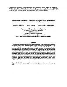
(or unacceptable, in the case of standardised encryption algorithms). The second approach is much more feasible. Dualrail logic and other symmetrical codes are highly suitable for this purpose. In this paper we consider the following mechanisms exposing the algorithm via the power consumption channel: data-dependent number of transitions in flip-flops data-dependent number of transitions and their energy in the multilevel combinational logic data-dependent hazards in combinational logic mode-dependent switching between sub-blocks. All these information ‘leaks’ can be minimised by creating circuits as dual-rail (other monotonic codes are also possible, e.g. 1-of-4 [3]) having return-to-spacer protocol on each pair of wires. One wire within each pair switches at every clock cycle, thus making the number of switching events on these wires data-independent. Furthermore, if the combinational logic is made symmetrical by implementing it using complimentary gates (similar to NCL-X [7]), then the power consumption can be made constant within any clock cycle. The method and the tool for generating and optimisation of such combinational circuits is described in the following sections. As our designs are synchronous, a new flip-flop supporting the return-to-spacer protocol has been implemented. A. Dual-rail logic Dual-rail code ������offers ������ two rails with only two valid signal , which encode values 0 and 1 respeccombinations tively. Other combinations do not belong to the code space. Dual-rail code is widely used to represent data in self-timed circuits [4], [5], where a specific protocol of switching helps to avoid hazards. The protocol allows only the transitions from all-zeroes, which is a non-code word, to a code word and back to all-zeroes as shown in Fig. 1(a). The all-zeroes state is used to indicate the absence of data, which separates one code word from another. Such a state is often called a spacer. It is important that any transition in Fig. 1(a) changes the same number of signals, which results in the balanced and data-independent power signature. Spacer Sp0 00 "0" "1" 10 Code words
01
(a) Allowed transitions
a1 a0
c1
b1
c0
b0
(b) XOR implementation
Fig. 1. Self-timed dual-rail code
Spacer-to-code switching is monotonic as the number of ones is only increasing. The opposite transition is also monotonic. Functional operations on dual-rail signals can be im-
plemented as dual-rail logic, an example of which is shown in Fig. 1(b). These implementations exploit the fact that the negation operation in dual-rail corresponds to swapping the rails. Such circuits do not have negative gates hence they are race-free (internal negative gates in XOR elements are also converted into positive gates) under any single transition. In order to avoid hazards in the series of transitions it is necessary either to introduce completion detectors for all internal signals [6], [7], [8] or to guarantee sufficient duration of input states ‘code word’ and ‘spacer’, as we do in our clocked designs. A disadvantage of building circuits out of positive gates is that such gates are constructed in CMOS out of a negative gate and an inverter. In this paper we present a method for negative gate optimisation of dual-rail logic which eliminates most internal inverters and results in smaller and faster circuits. B. Negative Gate Optimisation If the all-zeroes spacer of the traditional dual-rail code is applied to a layer of negative gates (NAND, NOR, ANDNOR, OR-NAND), then the output will be all-ones. The opposite is also true: all-ones are converted into all-zeroes. Such spacer transformations are captured in Fig. 2. The polarity of signals within code words remains the same.
~sp
a1 a0 b1 b0
~sp
q1 ~sp
a b
c1 c0
q
c
q0 Spacer polarity converter
(a) Original single-rail circuit
(b) DSDR implementation
Fig. 3. Constructing dual-spacer dual-rail circuit
same time it makes the power consumption data-dependent. In order to avoid this, we make flip-flops operate in the returnto-spacer protocol as in Fig. 1(a). The solution in Fig. 4 uses the master-slave scheme, writing to the master is controlled by the positive edge of the clock and writing to the slave is controlled by the negative edge. At the same time the high value of the clock enforces slave outputs into zero (output spacer) and the low clock value enforces master outputs into one (internal spacer). d_code
m_code
q_code
Code words
11 Spacer Sp0
s_En
m_nEn
01 "0" "1" 10 Code words
01 "0" "1" 10
s_Res
Spacer Sp0 00
m_nRes
Odd layers of logic
Even layers of logic
Fig. 2. Spacer transformation
This concept is illustrated in Fig. 3, where a single-rail logic circuit is transformed into a Dual Spacer Dual Rail (DSDR) circuit. Dotted lines in the single-rail circuit indicate signals which will be mapped into the dual-rail with the all-ones spacer. The bar on the wire is the location of a spacer polarity converter. The DSDR circuit in Fig. 3(b) is obtained by replacing gates by their DSDR versions. DSDR gates are build from the traditional positive dual-rail gates by adding signal inversion to their outputs and swapping the output rails (the latter is needed to preserve the polarity of signals in the output code words). The operation of negation is implemented as a separate element, which, however, does not require any logic gates (rail swapping). The spacer polarity converter is implemented as a pair of inverters having their outputs crossed in order to preserve the polarity of signals in the output code words. From this example one can see that the DSDR approach helps to reduce circuit latency by removing inverters from the critical path. Spacer polarity converters are inserted in order to ensure the alternation of spacer polarities in all paths. They neither belong to the existing nor create a new critical path. C. Dual-rail flip-flop Synchronous flip-flops are build to be power efficient, so if they switch to the same value (data input remains the same within several clocks) then nothing changes at the output. The absence of the output transition saves power, but in the
clk
(a) Schematic
clk+
clk−
m_nRes+
m_code−set
m_nEn+
s_Res+
s_Res−
q_code−set
s_En−
m_nRes−
q_code−reset
m_code−reset
(b) Signal transition graph Fig. 4. Dual-rail flip-flop
This circuit operates as explained in Fig. 4(b). Both master and slave latches have their respective reset and enable inputs (negative polarity for the master). The delay between removing the reset signal and disabling writing for each latch (hold time) is formed by the couple of buffers in the clock circuit. Buffers between master and slave are needed to delay m_code ‘set’ value until s_En-. The advantage of this implementation is the use of a single cross-coupled latch in each stage for a couple of input data signals. It is possible only because there can be only three states (two code words and one spacer) at a dual-rail input.
III. T OOL FOR
GENERATING
DSDR
CIRCUITS
single-rail.
The diagram of the Verimap tool is presented in Fig. 5. The input for the tool is a Verilog netlist. The gates used in the netlist and the gates complementary to them must be defined in the library.
b
co
a s
ci
Fig. 6. Full adder (single-rail)
RTL netlist
Let us consider the tool operation on the example of full adder shown in Fig. 6.
convertion into positive logic DR positive logic DR netlist
b1
rules for logic
optimisation for
spacer protocol
transformation
negative logic DR
on interface
negative logic DR netlist
co1
b0
co0
and1 (d=1)
or1 (d=3)
library of gates
constraction of
and2 (d=2) a1 a0
completion completion netlist
s1
xor2 (d=1)
ci1 ci0
s0 xor2 (d=2)
Fig. 7. Full adder (dual-rail)
construction of 1−2−1 rail converter 1−2−1 converter netlist
The dual-rail circuit is built by duplicating all the wires and replacing all gates by corresponding dual-rail elements as shown in Fig. 7.
Fig. 5. Verimap diagram
The rules for logic transformation into dual-rail specify the direct and complementary logic gate names, the sets of inverted inputs and outputs, the requirement of completion detection and inversion of the spacer for each gate in the library. If a predefined dual-rail implementation of a gate is found in the library the tool uses it, otherwise such an implementation is built automatically using the rules. Dual-rail logic can be optimised for negative gates. For this all inverters in positive dual-rail logic are replaced by swapping of the rails. In addition to inversion of a code word this operation also inverts the spacer, which may result in different spacers on the inputs of some elements. In order to allign the spacers the depth of each gate is calculated and a spacer inverter is inserted in the connection between the gates if their depth difference is an even number. The user defined spacer protocol on inputs and outputs of the circuit is preserved. If required, the tool generates the completion signals in the following way. First, the logic is sliced into layers of equal depth. Second, every element which requires completion is supplemented by either OR-gate (for all-zeros-spacer) or NAND-gate (for all-ones-spacer) connected to its output rails. This gates generate the completion signals. Then, the completion signal for each layer is built using a multi-input C-element, joining the completion signals from the individual elements of the given layer and the completion signal from the previous layer of logic. Finally, the go input is connected to the input of the first layer C-element and the done output is generated by the last layer C-element. To preserve the interface to the single-rail environment the tool creates a wrapper module which converts the circuit inputs from single-rail to dual-rail and outputs from dual-rail to
spinv1 (d=2) ~sp
~sp
~sp
b1
co1
b0
co0
~sp
and1 (d=1)
or1 (d=3)
~sp
and2 (d=2)
a1 a0
~sp s1
xor1 (d=1)
s0
ci1 ci0 xor2 (d=2)
Fig. 8. Full adder (dual spacer, dual-rail)
The full adder optimised for negative logic is shown in Fig. 8. The dotted lines indicate the rails of all-ones spacer and solid lines represent the rails with all-zeros spacer. This circuit is generated in the following way. First, each positive dual-rail gate is split into corresponding negative dualrail gate and not inverting spacer dual-rail inverter (which is a pair of inverters, one on each rail). Second, the inverter is replaced by spacer inverting dual-rail inverter (which is just a swapping of rails). Then, a spacer inverter spinv1 is inserted between and1 and or1 elements because their depth difference is even, which indicates a spacer conflict. The depth of an instances are shown in parenthesis next to their names. Here are some statistics for different full adder implementations. The full adder circuit optimised for negative logic uses 8 inverters less than the not optimised one (10 inverters are removed and 2 inverters are inserted for spacer inversion). The critical path (carry flag calculation) has been shorten by 3
inverters compared to the single-rail one. CMOS implementation of the single-rail full adder uses 38 transistors, dual-rail – 76 transistors, negative logic optimised dual-rail – 60 transistors (which is only 1.58 times more than in the single-rail circuit). IV. C ASE
the data). This results in a very even distribution of power supply current (/V0/MINUS waveform).
STUDY
In this Section we compare two implementations of the benchmark incr8 using a ripple-carry adder, one is dual-rail, the other is single-rail. The benchmark loads the value of 0xFC into the 8-bit register and then increments this value with each clock cycle. Both implementations use AMS0.35� technology and are simulated using the analog simulator Cadence Spectre. A clock frequency of 20MHz is chosen, which is typical for smart card applications. Simulation goes until the carry on all bits occurs (0xFF -> 0x00). Then the waveforms of current during this transition is compared against the transition without carry.
Fig. 10. Dual-rail circuit operation
Fig. 9. Benchmark incr8 (dual-rail)
The circuit in Fig. 9 is the dual-rail implementation of incr8. It uses full adders as in Fig. 8 and dual-rail flip-flops as in Fig. 4. A couple of inverters I24, I26 form the dual-rail input (with spacers) for the adders. Blocks I16-23 are combinational circuits enforcing the state 0xFC at the flip-flop inputs during reset. The waveforms in Fig 10 illustrate circuit operation. Flip-flops are triggered by the positive edge of the clock. One can see that all dual-rail signals are zero (spacer) when the clock is high. During this time the state of the system is stored in the master part of the flip-flops. It propagates to the output of flip-flops only at the beginning of the low phase of the clock. This is the moment when the combinational logic computes the next state. One can also see that the number of transitions is constant in each clock cycle (independent from
The diagrams in Fig. 11 show the waveforms of the power supply current under different operations performed by the circuit. The diagrams (a) and (b) correspond to writing of data into the master parts of flip-flops. The minor differences in these waveforms are possibly due to early propagation effects in the combinational logic being reset to spacer in the same time. It is important that the area under graphs remains the same, which indicates the same power consumed within each pulse. The diagrams (c) and (d) are superpositions of the current during the addition performed by combinational logic and the power signature of flip-flops writing data from masters into slaves and resetting masters. One can see the long trails caused by computations in the ripple-carry adders. The trail in (d) is longer as all 8 carry signals are computed sequentially. The trail in (c) is shorter due to early propagation effects in the combinational logic. Early propagation happens when some signals (carry in this case) are not needed for output computation. These dual-rail signals are still switched, but this is done concurrently with outputs. This is why the shorter trial is also higher. The area under the graphs is identical because of the same number of switching performed. A similar experiment has been performed with the single-
(a) 1 flip-flop bit changing
(b) 8 flip-flop bits changing
(c) no carry (early output generation)
(d) 8 carry operations
Fig. 11. Power supply current for the dual-rail circuit
rail implementation of the same benchmark. Full adders and flip-flops were taken from AMS-0.35� HRDLIB library. They are optimised at the transistor level, hence consume less power. Power signature, however, for this circuit depends heavily on data, thus allowing an observer to guess which part of the algorithm is performed. Waveforms of the power supply current for this circuit are shown in Fig. 12. The diagram (a) shows the current when only one flip-flop bit is changed and only one carry is generated. The long trail in (b) corresponds to the computation involving sequential generating four carry signals, while only one flip-flop changed its state. The burst of power consumption in (d) corresponds to switching eight flip-flops to new states. The area is clearly different under all these graphs, which means different energy consumed. Comparing these benchmarks, one can see that the overall power consumption of the dual-rail circuit is significantly higher. This is mainly because it switches all bits of data (each represented as a pair of wires) twice within the cycle of operation. It is about four times more than a corresponding single-rail circuit. In this experiment we did not optimise the flip-flops at the transistor level, they all also include delay elements (buffers) which could be shared between flip-flops. We
estimate the possible reduction in power consumption due to flip-flop optimisations to be about 15%. V. C ONCLUSIONS We used the dual-rail code with return-to-spacer protocol to build hazard-free combinational logic for synchronous circuits targeted for security applications. Due to the symmetry of representation of values in this code and to the symmetry in dual-rail logic implementation the number of switching in each clock cycle became constant. This resulted in a very balanced power consumption, independent from data processed. Special dual-rail flip-flops have been designed, which use a single cross-coupled latch for the master and a similar single latch for the slave implementation. These flip-flops generate spacers internally, which balances their power signature, and externally, which balances the power signature of the combinational logic. A benchmark using a ripple-carry adder has been implemented in the dual-rail and single-rail versions in AMS-0.35� technology. Both implementations have been simulated using the analog simulator Cadence Spectre. Simulation results indicate a significant reduction in data-dependency of the power supply current in the dual-rail circuit. The dual-
(a) 1 flip-flop output changing, 1 carry computed
(b) 1 flip-flop output changing, 8 carries computed
(c) 8 flip-flop outputs changing, no carry computed Fig. 12. Power supply current for the single-rail circuit
rail circuit consumes more power as it switches all dual-rail signals twice during the clock cycle, one time into the useful value and the second time to the spacer. The overall power consumption of the dual-rail circuit was about four times greater than that of the single-rail. The authors believe that this can be reduced if the new flip-flops are optimised at the transistor level and if 1-of-4 codes are used. The method for negative gate optimisation of dual-rail logic has been developed. It uses spacers of different polarity in different levels of combinational circuits. The tool for dual-rail logic optimisation has been created. The benchmark results indicate only 60% overhead comparing to the singlerail logic implementations. The tool is interfaced to Cadence CAD system. R EFERENCES [1] R.J. Anderson, M.G. Kuhn: ‘Low cost attacks on tamper resistant devices’. In M. Lomas et al. (ed.): Security Protocols, 5th Int. Workshop, Paris, France, 1997, Proceedings, Springer LNCS v 1361, pp 125-136. [2] S. Moore, R. Anderson, P. Cunningham, R. Mullins and G. Taylor: ‘Improving smart card security using self-timed circuits’. ASYNC’2002, 2002, pp 211–218. [3] W. J. Bainbridge and S. B. Furber: ‘Delay insensitive system-on-chip interconnect using 1-of-4 data encoding’. In Proc. ASYNC’2001, March 2001. [4] VARSHAVSKY, V., KISHINEVSKY, M., MARAKHOVSKY, V.,
[5] [6] [7] [8]
ROSENBLUM, L., and TAUBIN, A. : ‘Self-timed control of concurrent processes’ (Kluwer, 1990), (Russian edition 1986). DAVID, I., GINOSAR, R., and YOELI, M.: ‘An efficient implementation of boolean functions as self-timed circuits’. IEEE Trans. on Computers, 1992, 41(1), pp. 2–11. SPARSO, J., and FURBER, S. (Editors): ‘Principles of asynchronous circuit design - a systems perspective’ (Kluwer, 2001). KONDRATIEV, A., and LWIN, K.: ‘Design of asynchronous circuits using synchronous CAD tools’. Proc. DAC’02, New Orleans, USA, 2002, pp. 107–117. FANT, K., and BRANDT, S.: ‘Null Convention Logic: a complete and consistent logic for asynchronous digital circuit synthesis’. Proc. Int. Conf. Application-Specific Systems, Architectures and Processors (ASAP’96), IEEE CS Press, Los Alamos, Calif., 1996, pp. 261–273.
ACKNOWLEDGEMENT This work has been supported by EPSRC grants GR/R16754 (project BESST) and GR/S12036 (project STELLA).