information Article
Beamforming and Antenna Grouping Design for the Multi-Antenna Relay with Energy Harvesting to Improve Secrecy Rate Weijia Lei and Meihui Zhan * Chongqing Key Laboratory of Mobile Communications Technology, Chongqing University of Posts and Telecommunications, Chongqing 400065, China;
[email protected] * Correspondence:
[email protected] Academic Editor: Lorenzo Mucchi Received: 27 April 2016; Accepted: 1 July 2016; Published: 13 July 2016
Abstract: The physical security strategy in the wireless network with a single-antenna eavesdropper is studied. The information transmits from a single-antenna source to a single-antenna destination, and an energy-limited multi-antenna relay is employed to forward information. The antennas of the relay are divided into two groups. One group receives and forwards information, and the other converts the received signal into energy. Beamforming is used by the relay to prevent the eavesdropper from intercepting confidential information. For the purpose of maximizing the secrecy rate, antenna grouping and beamforming vectors are designed. A low complexity scheme of antenna grouping is presented. The simulation results show that the secrecy rate can be significantly improved by arranging part of the antennas for energy harvesting, and part for forwarding and optimizing the beamforming vector at the relay. The antenna grouping scheme significantly reduces the computational complexity at the cost of acceptable performance loss. Keywords: physical layer security; energy harvesting; multi-antenna relay; beamforming; antenna grouping; secrecy rate
1. Introduction Due to the openness of the wireless transmission medium, information faces serious security threats in wireless networks. Physical layer security, based on information theory, utilizes the physical characteristics of channels to achieve secure transmission [1,2]. Secrecy rate is an important parameter to measure the confidential performance of a secure system [3]. Much literature has showed that relay cooperation can enhance the performance of physical layer security effectively. The cooperation protocols include amplify-and-forward (AF), decode-and-forward (DF), and cooperative jamming (CJ). In [4], the security performances of three cooperation protocols have been analyzed when there are one or more eavesdroppers. In [5], AF and artificial noise (AN) are simultaneously employed to improve the secrecy rate under the condition of imperfect channel state information (CSI). In [6], multiple relays are used, one of which is selected for CJ relay and others for AF relay. In [7], two cooperation schemes are proposed in AF relay networks, in which jamming signals can be sent by the destination or a relay. With the rapid development of wireless network technology, energy consumption in wireless communication networks is also increasing. Energy harvesting is an effective way to prolong the lifetime of wireless nodes. Furthermore, wireless energy transmission is a method to realize energy harvesting and overcome the limitation of energy stored in the battery of a node [8]. Some references have researched the application of wireless energy transmission in relay networks, e.g., [9–12]. In [9,10], an energy cooperation protocol is proposed to promote throughput. In [11], a multi-antenna relay uses different antennas to receive information and harvest energy simultaneously. The throughput maximization of a wireless powered communication network with cooperation is studied in [12]. Information 2016, 7, 38; doi:10.3390/info7030038
www.mdpi.com/journal/information
Information 2016, 7, 38
2 of 11
The issue of the secure information transmission also exists in energy harvesting networks, and some researchers have studied the physical layer security in them. Two kinds of receivers, i.e., energy receiver and information receiver, are considered in [13,14] and [15]. In these articles, energy and secrecy information are transmitted simultaneously, and energy receivers are treated as eavesdroppers. Some strategies of optimizing secrecy rates have been proposed when the CSIs are both perfect and imperfect. Ref. [16] is an overview of the security problem in wireless powered systems, and the physical security techniques for wireless information and power transfer in relaying systems are reviewed. The security problem in wireless powered relaying systems is studied in [17,18]. Ref. [17] focuses on the beamforming of signal and artificial noise. Ref. [18] studies the wireless transmission for both secure information and power in a large-scale relaying system with imperfect CSI. In this paper, we focus on the physical layer security in an energy harvesting relay network. There are two receivers in the network, and the information sent to a receiver needs to be kept secret from the other receiver, so each is the eavesdropper of the other. When there are some obstacles between the source and the receivers, since no direct communication link exists, the information should be forwarded by a relay. The power supply of the relay is limited because of its location, so it needs to harvest energy from the received RF signals to increase the forwarding power. In our scheme, the relay’s antennas are divided into two groups, with one group amplifying and forwarding the source’s signal, and the other converting the received signal to energy for the forwarding. With the constraint of the source transmitting power, we propose a low complexity antenna grouping scheme, and optimize the beamforming vector of AF to achieve the maximal secrecy rate. The remainder of this paper is organized as follows. The second section describes the system model. In the third section, we give the mathematical model of the optimization problem, antenna grouping schemes and the beamforming vector. The simulation results are given in the fourth section. The last section is the conclusion. 2. System Model A source (s) transmits information to two receiving nodes, but the information transmitted to one node needs to be kept secret from the other node. Hence, for one receiver, the other receiver is an eavesdropper. Without loss of generality, in a timeslot, the node that receives information is called the destination (d), and the other node is called eavesdropper (e). Since obstacles are present between the source and the receivers, there is no direct link between the source and any receiving node, and, as a result, the information must be forwarded by a relay (r). The system model is shown in Figure 1. The relay is equipped with M antennas. Since the signal sent to both receivers needs to be forwarded Information 2016, 7, 38 3 of 11 by the relay, and the relay may ask them to feedback CSI, we assume that the relay can obtain all the CSIs. more All channels are unrelated to each other,that andare they are quasi-static, memoryless, and flat way, power is focused on the antennas better for forwarding. Although theundergo achievable Rayleigh Inwill addition, the noise at of any is additive complex Gaussian noise rate of thefading. first hop decrease, the rate thenode second hop willwhite obviously increase, so that thewith rate 2. zero-mean and variance σ of the system will be promoted. Destination (d)
Relay(r)
hsr
Source (s)
g sr
…
hrd
… hre
Eavesdropper (e)
Figure 1. System model. Figure 1. System model.
Ψ is defined as the set of relay antennas and Ψ M , wherein
represents the amount of
antennas in the set. The set is divided into two subsets of Θ and Ω , and satisfies Ψ Θ Ω , Θ N , and Ω M N . The antennas in the subset Θ are used to relay information, while the
Information 2016, 7, 38
3 of 11
With the constraints of location and environment, in our model, the relay cannot be powered by power lines. Because the energy stored in relay’s battery is limited, the power used for information forwarding is very small, so the data rate will be very low. The rate system will be restricted by the rate of the second hop, in spite of the high achievable rate of the first hop. To alleviate the limit of power supply, we propose an “energy harvesting-AF” strategy. The process of transmission from the source to the destination is divided into two stages. In the first stage, the source sends information; one group of the relay’s antennas receives the confidential information, while the other group receives RF signals and converts it into energy. In the second stage, the relay amplifies and forwards signals with the energy both harvested in the first stage and stored in its battery. In this way, more power is focused on the antennas that are better for forwarding. Although the achievable rate of the first hop will decrease, the rate of the second hop will obviously increase, so that the rate of the system will be promoted. Ψ is defined as the set of relay antennas and |Ψ| = M, wherein |¨| represents the amount of antennas in the set. The set is divided into two subsets of Θ and Ω, and satisfies Ψ “ Θ Y Ω, |Θ| “ N, and |Ω| “ M ´ N. The antennas in the subset Θ are used to relay information, while the antennas in the subset Ω are used to harvest energy. We denote the channel coefficient vector between the source and the antennas in the subset Θ as hsr , and the channel coefficient vector between the source and the antennas in the subset Ω as g sr . The channel coefficient vectors from the antennas in the subset Θ to the destination and the eavesdropper are denoted by hrd and hre , respectively: hsr P C N ˆ1 , g sr P Cp M´ N qˆ1 , hrd P C N ˆ1 , hre P C N ˆ1 . ” ı In the first stage, the source transmits symbol x with unit power, i.e., E |x|2 “ 1, where E r¨s denotes expectation. The source has a transmit power constraint Ps . The received signal of the relay can be expressed as: a yr “ Ps hsr x ` nr (1)
where nr „ CNp0, σ2 I N q are the additive noises received by the antennas in the subset Θ. Meanwhile, the relay harvests energy through the antennas in the subset Ω. We assume that Pr is the power constraint of the relay when only the energy stored in its battery can be used. When Ω = ∅, all antennas of the relay are used to forward signals. In this case, the practical power constraint of the relay is Pr 1 “ Pr . If Ω ‰ ∅, the received signal of the i-th pi “ 1, 2, ¨ ¨ ¨ , M ´ Nq antenna in the subset Ω can be expressed as: a ri “ Ps gsr,i x ` n1r,i (2) where n1r,i denotes the additive noise received by antenna i. Assume that the signal is converted to energy with the efficiency of α, and α P p0, 1s. As the harvested energy is also used in AF, the total power of forwarding signals in the second stage will be: Pr 1 “ Pr ` α “ Pr ` α
Mÿ ´N
|ri |2
i “1 Mÿ ´N ´
¯ ˇ ˇ2 Ps ˇ gsr,i ˇ ` σ2
(3)
i “1
“ Pr ` αPs ||gsr ||2 ` α pM ´ Nq σ2 In the second stage, the relay forwards information by the antennas in the subset Θ. The transmitted signal of the relay is denoted by xr “ Wyr , where W is a diagonal matrix composed of a beamforming vector w “ rw1 , w2 , ¨ ¨ ¨ , w N sT , i.e. W“ diag pwq. xr can be rewritten as: ? xr “ Wyr “ Ps W hsr x ` W nr ? “ Ps diag phsr q wx ` diag pwq nr
(4)
Information 2016, 7, 38
4 of 11
The transmission power of the relay should satisfy the constraint Equation (5) as follows: ||xr ||2 “ Pr 1
(5)
The received signals at the destination and the eavesdropper are: ? yd “ hTrd xr ` nd “ Ps hTrd diag phsr q wx ` hTrd diag pwq nr ` nd ? “ Ps hTrd diag phsr q wx ` nTr diag phrd q w ` nd ? T ye “ hre xr ` ne “ Ps hTre diag phsr q wx ` hTre diag pwq nr ` ne ? “ Ps hTre diag phsr q wx ` nTr diag phre q w ` ne
(6)
where the superscript T denotes matrix transpose, nd and ne , respectively, represent the noise at the destination and the eavesdropper. The SNRs (Signal to Noise Ratios) at the destination and the eavesdropper can be calculated as: γrd “ γre “
˚ T Ps wH diagph˚ sr qhrd hrd diagphsr qw 2 σ2 wH diagph˚ rd qdiagphrd qw`σ ˚ T Ps wH diagph˚ sr qhre hre diagphsr qw 2 σ2 wH diagph˚ re qdiagphre qw`σ
(7)
3. Optimization Analysis In information-theoretical security, the secrecy rate is defined as max tRd ´ Re , 0u, where Rd and Re are, respectively, the rates at the destination and the eavesdropper. In our model, they can be formulated as: ˆ ˙ Rd “ 21 log p1 ` γrd q “ 21 log 1 ` ˆ 1 1 Re “ 2 log p1 ` γre q “ 2 log 1 `
˚ T Ps wH diagph˚ sr qhrd hrd diagphsr qw 2 σ2 wH diagph˚ q rd diagphrd qw`σ
˚ T Ps wH diagph˚ sr qhre hre diagphsr qw σ2 wH diagph˚ diag phre qw`σ2 q re
˙
(8)
In the formulae, the coefficient 1/2 means the relay forwards data in half the time of a time slot. Thus, the secrecy rate is: ˆ Rs “
1 2 log
˚ T Ps wH diagph˚ sr qhrd hrd diagphsr qw 2 σ2 wH diagph˚ q rd diagphrd qw`σ
1` ˆ ´ 21 log 1 `
˙
˚ T Ps wH diagph˚ sr qhre hre diagphsr qw 2 σ2 wH diagph˚ re qdiagphre qw`σ
˙
(9)
The beamforming vector w is constrained by Equation (10) as follows: ´ ¯ wH Ps diag ph˚sr q diag phsr q ` σ2 IN w “ Pr 1
(10)
where I N is an N ˆ N identity matrix. The optimization problem can be formulated as: max
N,Θ,Ω,w
s.t.
Rs ˘ ` wH Ps diag ph˚sr q diag phsr q ` σ2 IN w “ Pr 1
(11)
As the channels are quasi-static, the channel coefficients over a period of time will be constant. The maximum Rs can be obtained by optimizing four optimization variables: N, Θ, Ω, and w. The first three variables determine the antenna grouping. If the antenna grouping has been determined, i.e., the variables N, Θ and Ω are known, the original optimization problem can be simplified into the optimization of the beamforming vector w. Therefore, the original optimization problem of formula (11) can be split into two parts. The first part is the optimization of w under a certain N, Θ and Ω, and the second is to determine the antenna grouping. An exhaustive antenna grouping scheme, which tries all the possible combinations of N, Θ, and Ω and obtains corresponding w and secrecy
Information 2016, 7, 38
5 of 11
rate Rs , can be used to get the optimal solution. This scheme has the optimal performance, but with a very high complexity. Therefore, we propose a low complexity antenna grouping scheme. Θ and Ω are determined according to an antenna choosing rule at a given N, and then w is calculated. M secrecy rate Rs will be obtained as N increases from 1 to M. The N, Θ, Ω and w that correspond to the maximum Rs are the optimized antenna grouping and beamforming scheme we are looking for. The performance of this scheme is sub-optimal because we have not tried all the possible grouping of the antennas, but its computational complexity is significantly lower than that of the previous grouping scheme. 3.1. Beamforming Design In this section, we optimize the beamforming vector at a given antenna grouping. The original problem of formula (11) can be rewritten as: max w
s.t. where
1 2 log
´ 1`
¯
´
wH Aw ´ 21 log wH Bw`σ2 wH Rw “ Pr 1
A “ Ps diag ph˚sr q h˚rd hTrd diag phsr q , C “ Ps diag ph˚sr q h˚re hTre diag phsr q , R “ Ps diag ph˚sr q diag phsr q ` σ2 IN
1`
wH Cw wH Dw`σ2
¯
` ˘ B “ σ2 diag h˚rd diag phrd q D “ σ2 diag ph˚re q diag phre q
(12a)
(12b)
This problem only involves variable w. A and C are positive semi-definite matrices with size N ˆ N, and B, D, R are positive definite matrices with size N ˆ N. The objective function of optimization can be further organized as: 1 max 2 log p f 1 f 2 q w (13a) s.t. wH Rw “ Pr 1 where
H
1
Aw f1 “ w , wH C 1 w 1 2 B “ B ` σ {Pr 1 R, A1 “ A ` B1 ,
H
1
Dw f2 “ w wH B1 w D1 “ D ` σ2 {Pr 1 R C 1 “ C ` D1
(13b)
A1 , B1 , C 1 and D1 are positive definite matrices with size N ˆ N. Since log p¨q is a monotonically increasing function, formula (13a) is equivalent to maximizing f 1 f 2 . The overall optimization of f 1 f 2 is difficult. However, the maximum of f 1 and f 2 can be respectively obtained by solving the maximal generalized eigenvalues of pA1 , C 1 q and pD1 , B1 q. However, these two generalized eigenvectors corresponding to the two maximal generalized eigenvalues may not be equal. Therefore, we use a local optimal beamforming design. We find that hsr , hrd and hre have a more comprehensive impact on f 1 , so we will maximize f 1 by solving the maximal generalized eigenvalue of pA1 , C 1 q to get the generalized eigenvector, and use it as beamforming vector w. ˇ ( We have f 1max “ sup λˇdetpλC 1 ´ A1 q “ 0 , where λ represents eigenvalues. Denote the generalized eigenvector corresponding to f 1max as w1 . The local optimal beamforming vector based on the power constraints of the relay is: d wo “
Pr 1 w1 w1H Rw1
(14)
The secrecy rate can be obtained by formula (9) when w is substituted by wo . f may not be maximal when f 1 is maximal, so the value range of f 1 f 2 should be “ max 2 min max max ‰ f1 f2 , f1 f2 , the superscripts max and min represent the maximum and minimum of f 1
Information 2016, 7, 38
6 of 11
and f 2 . Since the two matrices in f 2 are diagonal matrices, based on the generalized eigenvalues of pD1 , B1 q, the maximum and minimum of f 2 can be formulated as: ˜ f 2max “ max 1 ` k ˜ f 2min
“ min 1 ` k
Pr 1
´
2 2 |hre,k | ´|hrd,k | 2
¯
¸
2
Ps |hsr,k | ` Pr 1 |hrd,k | `σ2 Pr 1
´
2 2 |hre,k | ´|hrd,k | 2
¯
¸
(15)
2
Ps |hsr,k | ` Pr 1 |hrd,k | `σ2
where k represents the number of antennas in subset Θ. 3.2. Antenna Grouping Scheme As the number of relay antennas is limited, the optimal antenna grouping scheme can be obtained N when |Θ| “ N. The total number of by trying all possible subsets Θ. The number of the subset Θ is C M M ř N “ 2 M ´ 1 when N varies from 1 to M. A subset Θ corresponds to a beamforming subset Θ is CM N “1
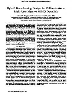
vector wo and secrecy rate Rs . The N, Θ, Ω and wo corresponding to the maximal Rs are the solutions of the optimization problem. The computation amount of wo and Rs is also 2 M ´ 1. Although this antenna grouping scheme can obtain the optimal solution, its computation complexity is too high. Here, we give a low complexity antenna grouping scheme with the acceptable performance loss. We find that the change of Θ and Ω will lead to the change of channel coefficients hsr , hrd , hre and gsr in Equation (9). Thus, we design a rule to determine Θ and Ω in a given N. Define hsr,k as the channel coefficient between the source and the k-th antenna of the relay, hrd,k and hre,k , respectively, as the channel coefficients from the k-th antenna of the relay to the destination and the eavesdropper, k “ 1, 2, ¨ ¨ ¨ , M. hrd,k and hre,k have a great impact on the secrecy transmission performance in the second stage. Obviously, in order to enhance security performance, we should choose the antenna that has a preferable channel performance to the destination but a poorer channel performance to ˇ ˇ ˇ ˇ eavesdropper to receive and forward information. Thus, we use ˇhre,k ˇ { ˇhrd,k ˇ as a metric to choose the ˇ ˇ ˇ ˇ AF antennas. Antenna k with a lower value of ˇhre,k ˇ { ˇhrd,k ˇ is more suitable for the forwarding. On the other hand, the amount of the energy harvested in the first stage will determine the transmitting power in the second stage, which has significant impact on secrecy performance, and it is determined by ˇ ˇ ˇ ˇ ˇhsr,k ˇ. Therefore, in theory, we should give priority to the antenna with large ˇhsr,k ˇ to harvest energy ˇ ˇ and the antenna with small ˇhsr,k ˇ to forward information. From the two aspects above, the antennas of the relay can be grouped according to the channel ˇ ˇˇ ˇ ˇ ˇ parameter p “ ˇhsr,k ˇ ˇhre,k ˇ { ˇhrd,k ˇ. We sort the antennas according to the descending order of p. The first M ´ N antennas are the members of subset Ω, and remaining antennas are the members of subset Θ. As N varies from 1 to M, there are M subsets Ω, Θ, and corresponding wo . The N and antenna grouping corresponding to the maximum of M secrecy rates will be the sub-optimal antenna grouping scheme. Here, we compare the complexity between the optimal and the sub-optimal antenna grouping schemes. The former searches and computes 2 M ´ 1 times, and the latter computes only M times. The sub-optimal antenna grouping scheme has evidently lower computational complexity. 4. Simulation Results The performance of the proposed scheme is simulated in this section. The coordinates of the nodes are shown in Figure 2. We set the source (s), the destination (d) and the eavesdropper (e), respectively, at p0, 0q, p200, 150q, p200, ´150q (Unit: m). For all channels, path loss and small-scale fading that obey Rayleigh distribution are considered, i.e. h “ βd´c{2 . Where, c “ 3 is the path loss exponent, d (unit: m) represents the distance between two nodes, and d´c{2 is the path loss (amplitude). In addition, β is the zero-mean complex Gaussian variable with unit variance, and it represents the small-scale fading factor. We set the variance of noise at all nodes to σ2 “ ´120 dBm. In the process of energy
respectively, at (0,0) , (200,150) , (200, 150) (Unit: m). For all channels, path loss and small-scale fading that obey Rayleigh distribution are considered, i.e. h βdc 2 . Where, c 3 is the path loss exponent, d (unit: m) represents the distance between two nodes, and d c 2 is the path loss (amplitude). In addition, β is the zero-mean complex Gaussian variable with unit variance, and it Information 2016, 7, 38
7 of 11
represents the small-scale fading factor. We set the variance of noise at all nodes to σ2 120 dBm . In the process of energy harvesting, the received signal power is converted to DC power with the 0.7 efficiency α [19]. signal The results showed in this section thetheaverage values of [19]. the data harvesting, the received power is converted to DC powerare with efficiency α “ 0.7 The obtained in 5000 trials. results showed inindependent this section are the average values of the data obtained in 5000 independent trials. d(200,150)
r
s(0,0)
e(200,−150)
Information 2016, 7, 38
8 of 11
Figure2.2. Model Modelused usedfor forsimulation. simulation. Figure
We compare our strategy with the traditional AF relay strategy, where the relay uses all We compare ourinformation. strategy withFurthermore, the traditional relaybeamforming strategy, where the relay all antennas antennas to forward theAF same as that in ouruses strategy is used to information. Furthermore, the same beamforming as that in our strategy is used in the in forward the traditional AF strategy. traditional strategy. FigureAF 3 shows the relationship between the relay position and secrecy rate. We set Ps 1 mW , Figure 3 shows the between the relayshow position rate. We set Ps “ of 1 mW, results thatand thesecrecy security performance the 6 . The simulation Pr 0.01 mW and M relationship P “ 0.01 mW and M “ 6. The simulation results show that the security performance of the proposed r proposed “energy harvesting–AF” strategy is better than the traditional AF strategy. In the “energy harvesting–AF” is better than the traditional AF strategy. traditional AF strategy, traditional AF strategy,strategy the relay forwards information only with In thethebattery energy, so the the relay forwards information only with the battery energy, so the forwarding power will be very forwarding power will be very low. Although the relay uses all antennas to forward information, low. Although uses all In antennas to forward information, the secrecy rate isthe stillrelay limited. the secrecy ratethe is relay still limited. the proposed “energy harvesting–AF” strategy, can In the proposed “energy harvesting–AF” strategy,therefore, the relay can supplement energy through energy supplement energy through energy harvesting; it will have higher forwarding power. harvesting; it will have higher forwarding Because rate of the logarithmic Because of therefore, the logarithmic relationship between thepower. transmission and SNR, therelationship increase of between the transmission rate and SNR, the increase of transmission power can bring significant transmission power can bring significant improvement of the transmission rate in the low power improvement the transmission rateincrease in the low region. On the hand, the increase of region. On theofother hand, with the ofpower distance between theother source andwith the relay, the path distance between the source and the relay, the path loss is also increasing, so the harvested energy is loss is also increasing, so the harvested energy is exponentially decreasing, and, consequently, the exponentially consequently, thethe secrecy of thetosystem decreases.its Although secrecy rate ofdecreasing, the systemand, decreases. Although relay rate is closer the destination, influencethe is relay is closer to the destination, its influence is far less than that of the decrease of the relay far less than that of the decrease of the relay forwarding power, so the secrecy rate of forwarding the system power, so It thealso secrecy of the system declines. alsosecrecy can be seen from 3 that the secrecy rate declines. can rate be seen from Figure 3 thatItthe rate of theFigure optimal antenna grouping of the optimal antenna is higher than sub-optimal one, butTherefore, the gap is not scheme is higher thangrouping that of scheme the sub-optimal one, that but of thethegap is not obvious. the obvious. Therefore, the sub-optimal antenna grouping scheme significantly reduces the computational sub-optimal antenna grouping scheme significantly reduces the computational complexity at only complexity at only theperformance cost of acceptable the cost of acceptable loss. performance loss. 9.5
Optimal antenna grouping Traditional AF strategy Suboptimal antenna grouping
9
R (bit/s/Hz) s
8.5
8
7.5
7
6.5
6
2
3
4
5
6
7
8
9
10
Distance between s and r (m)
Figure 3. 3. Relationship between relay’s relay’s position position and and secrecy secrecy rate. rate. Figure Relationship between
Figure 4 shows the secrecy rate with different source transmission power. We also set Figure 4 shows the secrecy rate with different source transmission power. We also set P 0.01 mW and M 6 , while the coordinate of the relay is fixed at (5,0) . The source Prr “ 0.01 mW and M “ 6, while the coordinate of the relay is fixed at p5, 0q. The source transmission transmission power Ps increases from 0.1mW to 1mW. We find that the secrecy rates of the proposed strategy with two antenna grouping schemes are both increasing when the source transmission power gets higher. This is because the increase of source transmission power on the one hand is beneficial to the improvement of the receiving SNR of the relay, and, on the other hand, can increase the harvested energy of the relay. However, in the traditional AF strategy, although
Information 2016, 7, 38
8 of 11
power Ps increases from 0.1 mW to 1 mW. We find that the secrecy rates of the proposed strategy with two antenna grouping schemes are both increasing when the source transmission power gets higher. This is because the increase of source transmission power on the one hand is beneficial to the improvement of the receiving SNR of the relay, and, on the other hand, can increase the harvested energy of the relay. However, in the traditional AF strategy, although the receiving SNR of the relay can also be improved by increasing source transmission power, the secrecy rate is not obviously improved due to the low forwarding power of the relay. In addition, it can also be found that the secrecy rate gap between the two antenna grouping schemes increases with the increase of source transmission power. The increase of the source transmission power leads to the increase of the receiving SNR and the harvested energy of the relay. The sub-optimal antenna grouping scheme prefers the antennas with better link quality to the source to harvest energy, and the effect of receiving signal SNR of the relay is not considered adequately. This will not have an obvious influence when source transmission power Information 2016, 7, 38 9 of 11 is low, but it will become serious when source transmission power is high. We also give the secrecy rate when the location of the eavesdropper is p100, ´75q, closer to the relay than the destination. As eavesdropper is (100, 75) , closer to the relay than the destination. As the eavesdropper only the eavesdropper only receives a signal in the second stage, where the secure beamforming is used, receives a signal in the second stage, where the secure beamforming is used, the secrecy rates are the secrecy rates are nearly the same. nearly the same. 7.6 Optimal antenna grouping, e at (200,-150) Ttraditional AF strategy,e at (200,-150) Suboptimal antenna grouping,e at (200,-150) Optimal antenna grouping,e at (100,-75) Ttraditional AF strategy,e at (100,-75) Suboptimal antenna grouping,e at (100,-75)
7.4
7
s
R (bit/s/Hz)
7.2
6.8
6.6
6.4
6.2 0.1
0.2
0.3
0.4
0.5 0.6 Ps (mW)
0.7
0.8
0.9
1
Figure 4. 4. Relationship Relationship between between source source transmission transmission power power and and secrecy secrecy rate. rate. Figure
The relationship between antenna number of the relay and secrecy rate is shown in Figure 5. The relationship between antenna number of the relay and secrecy rate is shown in Figure 5. We set the coordinate of the relay at (5,0) , and set Ps 1 mW and Pr 0.01 mW . M increases We set the coordinate of the relay at p5, 0q, and set Ps “ 1 mW and Pr “ 0.01 mW. M increases from from four to 10. For the traditional AF strategy, the increase of M will enhance beamforming gain, four to 10. For the traditional AF strategy, the increase of M will enhance beamforming gain, so the so the achievable secrecy rate can be improved. However, in the proposed “energy harvesting–AF” achievable secrecy rate can be improved. However, in the proposed “energy harvesting–AF” strategy, strategy, the increase of M has two benefits. One is that more antennas can be selected into the the increase of M has two benefits. One is that more antennas can be selected into the subset Θ, which subset Θ , which means that there are more antennas receiving and forwarding signals. In this case, means that there are more antennas receiving and forwarding signals. In this case, the beamforming the beamforming gain of the second stage will improve. The other is that more antennas can be gain of the second stage will improve. The other is that more antennas can be assigned to the subset Ω. assigned to the subset Ω . Thus, the forwarding power will increase because more energy is Thus, the forwarding power will increase because more energy is harvested by the relay. They are both harvested by the relay. They are both conducive to enhancing the security performance of the conducive to enhancing the security performance of the system. Therefore, with the increase of M, system. Therefore, with the increase of M , the secrecy rate of “energy harvesting–AF” strategy the secrecy rate of “energy harvesting–AF” strategy increases significantly. In addition, the “energy increases significantly. In addition, the “energy harvesting-AF” strategy can use the antennas more harvesting-AF” strategy can use the antennas more flexibly, so its performance is higher than that of flexibly, so its performance is higher than that of the traditional AF strategy. the traditional AF strategy. 8.5
8
7
s
R (bit/s/Hz)
7.5
6.5
6
Optimal antenna grouping Traditional AFstrategy Suboptimal antenna grouping
the beamforming gain of the second stage will improve. The other is that more antennas can be assigned to the subset Ω . Thus, the forwarding power will increase because more energy is harvested by the relay. They are both conducive to enhancing the security performance of the system. Therefore, with the increase of M , the secrecy rate of “energy harvesting–AF” strategy Information 7, 38 of 11 increases2016, significantly. In addition, the “energy harvesting-AF” strategy can use the antennas 9more flexibly, so its performance is higher than that of the traditional AF strategy. 8.5 Optimal antenna grouping Traditional AFstrategy Suboptimal antenna grouping
8
R (bit/s/Hz)
7.5
s
7
6.5
6
5.5
4
5
6
7 M
8
9
10
Figure 5. 5. Relationship Relationship between between antenna antenna number number of of relay relay and and secrecy secrecyrate. rate. Figure
Figure 66 illustrates illustrates the the relationship relationship between andsecrecy secrecyrate. rate.We Weset setthe thecoordinate coordinate of of the the Figure between PPrr and M 6 relay at , and set and . increases from 0.01 mW to 0.1 mW. Obviously, P 1 mW P (5,0) relay at p5, 0q, and set Ps “ from 0.01 mW to 0.1 mW. Obviously, the s 1mW and M “ 6. Pr increases r forwarding power of the affects directly the receiving SNRSNR of the Although the the forwarding power of relay the relay affects directly the receiving ofdestination. the destination. Although receiving SNR7,of eavesdropper is also affected, its promotion is less thanisthat the destination the receiving SNR the eavesdropper is also affected, its promotion lessatthan that 10 atofthe Information 2016, 38 the of 11 due to the beamforming. Thus, the secrecy rate increases raise ofwith Pr . From Figure find destination due to the beamforming. Thus, the secrecy with rate the increases the raise of 6,Pwe . From r Figure we of find the gap the secrecy rate between the “energy harvesting–AF” strategy and that the6,gap thethat secrecy rateof between the “energy harvesting–AF” strategy and the traditional AF the traditional AF when strategy is reduced when Due to thebetween logarithmic relationship strategy is reduced Pr increases. Due to thePlogarithmic transmission rate r increases.relationship and SNR,transmission the performance by energy harvestinginduced becomesby less evident when Pr between rate improvement and SNR, theinduced performance improvement energy harvesting becomes higher. less evident when Pr becomes higher. 8.2 8 7.8
7.4 7.2
s
R (bit/s/Hz)
7.6
7 6.8 6.6
Optimal antenna grouping Traditional AF strategy Suboptimal antenna grouping
6.4 6.2 0.01
0.02
0.03
0.04
0.05 0.06 Pr(mW)
0.07
0.08
0.09
0.1
Figure andsecrecy secrecyrate. rate. Figure6.6.Relationship Relationshipbetween between Prr and
5. Conclusions Conclusions
the security security transmission transmission in in wireless wireless powered powered relaying relaying systems. systems. In the This paper studies the system model, the source, the destination, and the eavesdropper are respectively equipped with an model, the source, the destination, and the eavesdropper are respectively equipped with antenna, andand the the relay is equipped withwith multiple antennas to amplify and and forward information. The an antenna, relay is equipped multiple antennas to amplify forward information. transmission process of confidential information was was divided into into two two stages. In the stage, the The transmission process of confidential information divided stages. In first the first stage, relay converts the received signals in some antennas into energy. In order to avoid the leakage of the relay converts the received signals in some antennas into energy. In order to avoid the information, beamforming beamforming is is used by the relay when it forwards the information to the destination in the second stage. We divide the antennas of the relay into two groups. The antennas in one group convert thethe received signal to forward the received received signals signalswith withbeamforming, beamforming,and andthose thoseininthe theother other convert received signal energy for the signal forwarding. We optimize the antenna grouping scheme and beamforming vector to promote the achievable secrecy rate. Since the overall optimal beamforming vector is difficult to obtain, we use a local optimal beamforming vector. We also propose a low complexity antenna grouping scheme at only the cost of acceptable performance loss. The simulation results show that the proposed “energy harvesting–AF” strategy has better security performance than the
Information 2016, 7, 38
10 of 11
to energy for the signal forwarding. We optimize the antenna grouping scheme and beamforming vector to promote the achievable secrecy rate. Since the overall optimal beamforming vector is difficult to obtain, we use a local optimal beamforming vector. We also propose a low complexity antenna grouping scheme at only the cost of acceptable performance loss. The simulation results show that the proposed “energy harvesting–AF” strategy has better security performance than the traditional AF strategy, especially when the battery power of the relay is low. Acknowledgments: We gratefully acknowledge the detailed and helpful comments of the anonymous reviewers, who have enabled us to considerably improve this paper. This work was supported by the National Natural Science Foundation of China (61471076, 61301123), the fund of the Changjiang Scholars and Innovative Team Development Plan (IRT1299), and the Special Fund of Chongqing Key Laboratory (CSTC). Author Contributions: Weijia Lei and Meihui Zhan conceived and designed the experiments; Meihui Zhan performed the experiments; Weijia Lei and Meihui Zhan analyzed the data; Meihui Zhan wrote the paper; Weijia Lei revised the paper. . Conflicts of Interest: The authors declare no conflict of interest.
References 1. 2. 3. 4. 5.
6. 7. 8. 9.
10. 11. 12. 13. 14. 15.
16.
Mukherjee, A.; Fakoorian, S.A.A.; Huang, J.; Swindlehurst, A.L. Principles of physical layer security in multiuser wireless networks: A survey. IEEE Commun. Surv. Tut. 2014, 16, 1550–1573. [CrossRef] Liang, Y.; Poor, H.V. Information theoretic security. Found. Trends Commun. Inf. Theory 2009, 5, 355–580. [CrossRef] Leung-Yan-Cheong, S.K.; Hellman, M.E. The Gaussian wire-tap channel. IEEE Trans. Inf. Theory 1978, 24, 451–456. [CrossRef] Dong, L.; Han, Z.; Petropulu, A.P.; Poor, H.V. Improving wireless physical layer security via cooperating relays. IEEE Trans. Signal Process. 2010, 58, 1875–1888. [CrossRef] Li, Q.; Yang, Y.; Ma, W.K.; Lin, M.; Ge, J.; Lin, J. Robust cooperative beamforming and artificial noise design for physical-layer secrecy in AF multi-antenna multi-relay networks. IEEE Trans. Signal Process. 2015, 63, 206–220. [CrossRef] Wang, H.M.; Liu, F.; Yang, M. Joint cooperative beamforming, jamming and power allocation to secure AF relay systems. IEEE Trans. Veh. Technol. 2015, 64, 4893–4898. [CrossRef] Ding, Z.; Leung, K.K.; Goeckel, D.L.; Towsley, D. Opportunistic relaying for secrecy communications: Cooperative jamming vs relay chatting. IEEE Trans. Wirel. Commun. 2011, 10, 1725–1729. [CrossRef] Bi, S.; Ho, C.K.; Zhang, R. Wireless powered communication: Opportunities and challenges. IEEE Commun. Mag. 2015, 53, 117–125. [CrossRef] Gurakan, B.; Ozel, O.; Yang, J.; Ulukus, S. Energy cooperation in energy harvesting wireless communications. In Proceedings of IEEE International Symposium on Information Theory, Cambridge, MA, USA, 1–6 July 2012; pp. 965–969. Gurakan, B.; Ozel, O.; Yang, J.; Ulukus, S. Energy cooperation in energy harvesting communications. IEEE Trans. Commun. 2013, 61, 4884–4898. [CrossRef] Zhou, Z.; Peng, M.; Zhao, Z.; Li, Y. Joint power splitting and antenna selection in energy harvesting relay channels. IEEE Signal Process. Lett. 2015, 22, 823–827. [CrossRef] Ju, H.; Zhang, R. User cooperation in wireless powered communication networks. In Proceedings of IEEE Global Communications Conference, Austin, TX, USA, 7–11 December 2014; pp. 1430–1435. Liu, L.; Zhang, R.; Chua, K.C. Secrecy wireless information and power transfer with MISO beamforming. IEEE Trans. Signal Process. 2014, 62, 1850–1863. [CrossRef] Feng, R.; Li, Q.; Zhang, Q.; Qin, J. Robust secure transmission in MISO simultaneous wireless information and power transfer system. IEEE Trans. on Veh. Tech. 2015, 64, 400–405. [CrossRef] Wu, W.; Wang, B. Robust downlink beamforming design for multiuser MISO communication system with SWIPT. In Proceedings of IEEE International Conference on Communications, London, UK, 8–12 June 2015; pp. 4751–4756. Chen, X.; Ng, D.W.K.; Chen, H.H. Secrecy wireless information and power transfer: Challenges and opportunities. IEEE Wirel. Commun. 2016, 23, 54–61. [CrossRef]
Information 2016, 7, 38
17.
18.
19.
11 of 11
Zhang, G.; Li, X.; Cui, M.; Li, G.; Yang, L. Signal and artificial noise beamforming for secure simultaneous wireless information and power transfer multiple-input multiple-output relaying systems. IET Commun. 2016, 10, 796–804. [CrossRef] Chen, X.; Chen, J.; Liu, T. Secure wireless information and power transfer in large-scale MIMO relaying systems with imperfect CSI. In Proceedings of IEEE Global Communications Conference, Austin, TX, USA, 7–11 December 2014; pp. 4131–4136. Valenta, C.R.; Durgin, G.D. Harvesting wireless power: Survey of energy-harvester conversion efficiency in far-field, wireless power transfer systems. IEEE Microw. Mag. 2014, 15, 108–120. © 2016 by the authors; licensee MDPI, Basel, Switzerland. This article is an open access article distributed under the terms and conditions of the Creative Commons Attribution (CC-BY) license (http://creativecommons.org/licenses/by/4.0/).