Mustang, Cobra, GT500 etc (Ford Returnless System '99-'12) utilizing “returnless”
... which can monitor fuel flow on the bench and actual HP and fuel flow on an
adjacent chassis dyno. ... 2) Fuel Pressure Feedback Sensor (GT, Cobra, Shelby)
.... Kenne Bell BOOST-A-PUMP® and/or “knock offs” have been implemented in.
BOOST-A-PUMP THEORY EXPLAINED IF MY FUEL PRESSURE IS DROPPING OFF, CAN I INSTEAD INSTALL BIGGER INJECTORS OR INCREASE MY PUMP DUTY CYCLE? Absolutely not. Without the BOOST-A-PUMP®, bigger injectors and increasing the pump duty cycle is not an option provided the pump was already at 100% duty cycle at WOT. Now, if you are Kenne Bell, you have the best of all worlds. We can install the BOOST-A-PUMP® (BAP) and allow the pump to operate much more efficiently, output more flow at the same pressure as before (up to 100%) AND then install bigger injectors, AND control the pump duty cycle with a tune! Example Test: ‘02 Mustang GT
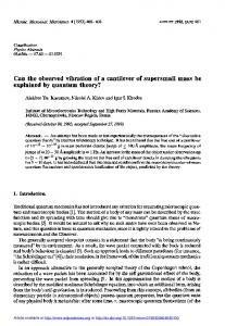
Figure 1
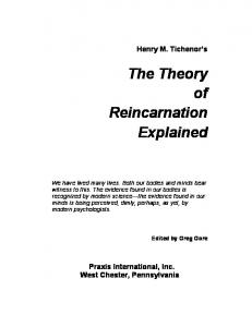
Figure 2 Read on for a more detailed discussion of how the Returnless Fuel System works.
There seems to be quite a bit of confusion among tuners and customers regarding fuel requirements for the Mustang, Cobra, GT500 etc utilizing “returnless” fuel systems. We’d like to take a moment to clear up some of this confusion. Since we get a lot of problem call backs, specifically from customers who have chosen not to use our BOOST-A-PUMP® with their kits, we feel it necessary to explain more in detail why you should use our complete kits, as we sell them, and use us as the Number One Source of information regarding our kits. There are a number of reasons why Ford, GM, Chrysler and all the other manufacturers chose to go to returnless fuel systems. One reason of course is cost, another deals with evaporative emissions, loss of octane and quality of fuel, and reducing temperature of the fuel (to help prevent boiling). There are others, but the main focus of this discussion is to assist in pointing out how to increase fuel requirements for elevated horsepower levels. What is not well understood by many tuners and customers is HOW to deliver the added fuel required. Kenne Bell has performed countless hours developing supercharger kits on vehicles using returnless fuel systems (both mechanical and feedback loop) with our Chassis, Fuel Flow and Supercharger Dyno’s, on the street and at the track. We use high speed dataloggers and the same air/fuel monitoring equipment the OEMs use to collect reams of data on fuel pressures, flows, mass air flows, pump voltages and duty cycles, and air/fuel ratios to study their relationship with fuel delivery. We know what works. We’ve done the homework and collected the data. Check out the one of a kind Kenne Bell Fuel Flow Dyno which can monitor fuel flow on the bench and actual HP and fuel flow on an adjacent chassis dyno. And we have tested all the popular upgrade pumps (255, 340, 400 etc.) in single and dual configuration. We possess the in-house ability to fully tune all domestic ECU’s to make them do what we want when we want. HOW ELECTRONIC RETURNLESS FUEL SYSTEMS WORK The fuel system is basically made up of the following: 1) Single Fuel Pump (Mustang GT), Dual Fuel Pumps (Cobra, Shelby, GT500, Ford GT etc.) 2) Fuel Pressure Feedback Sensor (GT, Cobra, Shelby) 3) Feedback Loop Control One main principle in delivering the correct amount of fuel relies on feedback from the Fuel Pressure Sensor mounted on the fuel rail. The ECU must monitor fuel pressure constantly and adjust the fuel pump duty cycle in relationship to manifold pressure (more on this later) to deliver the correct amount of fuel. Old return type fuel systems incorporated a mechanical fuel pressure regulator. The old style regulator has been replaced by software in the ECU, fuel pump driver module and fuel pressure sensor. Collectively, they now function as the “regulator”. The important thing often overlooked is that the nozzle outlet pressure of the injector MUST REMAIN CONSTANT against the forces of increasing/decreasing pressure in the manifold. Imagine a door you are trying to keep shut against the wind, but this door has no latch, so it’s up to you to keep enough pressure applied to keep it shut as the wind against it increases or decreases. In order to keep the door in the same position, you would have to apply equal force on your side against the wind speed (force) trying to open it. Now, what if you wanted to allow some air through the door, but you never wanted it to rush in faster or slower. The principle would still be the same as above with one exception: you would have to apply slightly more opposing force to the door at all times to keep the rush of air constant coming in as the wind changed. Now, an example of what goes on in your manifold: Let’s use an easy one. Suppose you have 10 psi boost inside your manifold. If an injector is rated at 39 psi operating pressure, what fuel pressure do you need to overcome the boost pressure in the manifold? Fuel rail pressure - manifold pressure = nozzle outlet pressure (or delta pressure). In order to keep the delta (Ford’s rated operating pressure) constant (39 psi), the fuel pressure in the rail would HAVE TO BE 49 psi at 10 psi boost, because 49 - 10 = 39.
Now, a not so easy one. If the idle pressure was 30 to 32 psi (typical on most Ford systems), how could you get 39 psi at the nozzle outlet in the manifold? Since the manifold now has vacuum and not boost, how can you produce 39 psi at the nozzle with only 30 psi in the rail? You can do it because remember the most important thing: it’s all about nozzle outlet pressure (delta). Because we read vacuum in inches, it’s confusing (who’s idea was that anyway?). Write this down: Every 1 psi of atmospheric pressure = 2.036 inches of mercury (Hg). So, if you are sitting there idling at 18 inches (Hg), how many psi would that be? Inches of Hg / 2.036 = psi or 18 inches Hg / 2.036 = -8.84 psi (ahh, only this is NEGATIVE boost) In order to keep the delta (Ford’s rated operating pressure) constant (39 psi), the fuel pressure in the rail would HAVE TO BE 30 psi at 18 inches vacuum, because 30.12 - -8.84 = 39 (Note: Gauges vary a little - if you see ~15 to 16 inches at idle, then you should see ~ 31 to 32 psi in the rail). Now you know what your fuel pressure should be at all times under all conditions: vacuum or boost! If you have 15 psi boost, then you better have 54 psi in the rail, right? What if the vacuum was 10 inches? Then you better have 34 psi in the rail (10 / 2.036 = -4.91, or 34.09 - -4.91 = 39). Another way to look at it is vacuum or boost + 39 = desired fuel rail pressure (-4.91 psi + 39 psi = 34.09 psi). This is where the ECU plays the important role: How does it determine what the fuel pressure in the rail needs to be at all times? The ECU could monitor manifold air pressure (MAP) and adjust the fuel pressure up this way, right? Not without a fuel pressure sensor also. That would cost more to have both. So, Ford does it this way: they already know what the fixed (delta) nozzle pressure must be at all times, right? 39 psi. How could you monitor manifold pressure (MAP) and fuel pressure at the same time with only one sensor? Many people believe the ECU “infers” what MAP is via TPS and mass air flow - NOT! Some people say the fuel pressure sensor also is a MAP sensor - NOT! The fuel delivery strategy needs only to monitor and adjust fuel pressure as long as a reference to vacuum / boost is applied to the fuel pressure sensor diaphragm! This is how it is done. Remember the door? If the manifold pressure is opposing the pressure from the fuel rail, and the ECU knows to add 39 psi at all time to the feedback pressure, could it be done? YES! How does the ECU actually control the pressure? By Pulse Width Modulating (PWM) the fuel pump, very similar to how an injector is pulse width modulated. The principle again is fairly simple: build a pump that you know can overcome the maximum fuel delivery requirements of the engine at the maximum pressure and flow rate, then slow the pump down to keep the pressure where you want it during all other conditions. Note: Have you noticed how “slowing down” and “speeding up” pumps has become standard practice on modern fuel systems - just like the Kenne Bell BAP concept. We have used the BOOST-A-PUMP® since 1995. The BAP kit is designed to work perfectly with these systems. Don’t be afraid of this new technology - we’ve been doing it for many years. There’s no real magic here: The ECU switches the voltage to ground more rapidly or slowly (duty cycle) dependent upon demand (pressure feedback from the rail sensor). Now for the kicker: Re-read the above paragraph: “...build a pump that you know can overcome the maximum fuel delivery requirements of the engine at the maximum pressure and flow rate...” Hmm... we added 50%+ more power and guess what? The pump isn’t going to make it even at the fastest duty cycle (100%). We’d like to show what happens to the pump PRESSURE and VOLTAGE once you’ve reached 100% duty cycle and the ECU wants to deliver more fuel, but it CAN’T (see FIG 1). The interesting thing here is many tuners think they can “play with” the pressure or raise the duty cycle. NOPE. Once you’re at 100% folks, that’s it. You only have two choices: 1) increase the existing pump’s output (flow) at the same given pressure or 2) install a bigger pump. BTW, merely increasing a pump’s pressure DOES NOT , WILL NOT, CANNOT INCREASE ITS OUTPUT IN FLOW. Another humorous one is “We’ll just put some bigger injectors in. That’ll fix ‘er”. NOPE. The pump is DONE, FINITO, KAPUT. Installing bigger injectors doth not maketh thy pump bigger.
In conjunction with our calibrations, we developed the BOOST-A-PUMP® to safely increase the work of the stock pump to deliver up to 100% more fuel. Note how the pressure begins to drop off at higher RPM in FIG 1. as well as voltage delivery to the pump (these are directly related to flow). Look at FIG 2. to see the effect of fuel delivery with the BOOST-A-PUMP®. Note how 100% Duty Cycle is never reached. Beautiful! The pump works much less and outputs much more fuel. BOOST-A-PUMP® FACTS - It’s All About Pain, Time and Money MYTH: “THE BOOST-A-PUMP® ISN’T RELIABLE” FACT: We have tens of thousands of these units in the field working flawlessly since 1996. And we have never seen a pump failure due to a BAP properly installed. The BAP is also the choice of musclecar builders such as Shelby, Saleen, Hurst etc. MYTH: “WE CAN JUST INSTALL BIGGER PUMP(S)” FACT: Bigger pumps are typically 1. more expensive to install, 2. can’t match the performance of the BAP with a stock pump, 3. lack a method of controlling the increased fuel delivery at idle, cruise and part throttle, or 4. require expensive new “hats,” feed and return lines, regulator and wiring to say nothing of an expensive re-tune. MYTH: “WE CAN TUNE IT - DON’T USE THEIR TUNE” FACT: Shops make money by “tuning”. Some do not realize they can’t make it work without the BOOST-APUMP® and our calibration together. MYTH: “THAT EXTRA VOLTAGE WILL HURT YOUR PUMP” FACT: The installation of our BOOST-A-PUMP® will actually increase pump life by reducing it’s workload. BTW, the BOOST-A-PUMP® only increases the voltage when required under boost conditions. It is a passive system otherwise. We want to make sure everyone understands: Of course you can install bigger pumps and get basically the same result, but why? It’s absolutely unnecessary and it’s painful, time consuming and will cost more. Also, our intention is not to “knock” people who are out there trying to make a living at installing aftermarket products or providing tuning services. This message is a service directly to our customers to aid them in making the right decisions on which way to go when installing Kenne Bell or other superchargers, turbochargers or other high HP applications. Thanks. Kenne Bell
jodibell\documents\corelfiles\BAPtheory.cdr rev 02/13/17


![[PDF] Download Wind Energy Explained: Theory, Design and ...](https://m.moam.info/img/260x300/pdf-download-wind-energy-explained-theory-design-a_6477492f097c474c228bdbc8.jpg)
![Download [PDF] Wind Energy Explained: Theory ... - Google Sites](https://m.moam.info/img/260x300/download-pdf-wind-energy-explained-theory-google-s_6477e755097c474e708c3882.jpg)

![[PDF] Wind Energy Explained: Theory, Design and ... - Google Sites](https://m.moam.info/img/260x300/pdf-wind-energy-explained-theory-design-and-google_647798c2097c474d228c37a3.jpg)
![[PDF] Download Wind Energy Explained: Theory ... - Google Sites](https://m.moam.info/img/260x300/pdf-download-wind-energy-explained-theory-google-s_6477c66d097c4737708c131a.jpg)
![free [download] wind energy explained: theory, design ... - Google Sites](https://m.moam.info/img/260x300/free-download-wind-energy-explained-theory-design-_6477c66d097c474b228c73ea.jpg)


![[Read] Ebook Wind Energy Explained: Theory, Design ... - Google Sites](https://m.moam.info/img/260x300/read-ebook-wind-energy-explained-theory-design-goo_64788e4d097c474d228d4865.jpg)
![[PDF] Download Wind Energy Explained: Theory ... - Google Sites](https://m.moam.info/img/260x300/pdf-download-wind-energy-explained-theory-google-s_64788f61097c474c228d44b5.jpg)
![free [download] wind energy explained: theory, design ... - Google Sites](https://m.moam.info/img/260x300/free-download-wind-energy-explained-theory-design-_647864d6097c474e708cc3b2.jpg)


