BSM Integrated PEP with Cross-Layer Improvements Haitham Cruickshank,
Robert J. Mort
University of Surrey, U.K.
[email protected]
Systek Consulting Ltd., Havant, UK
[email protected]
Giovanni Giambene Matteo Berioli
CNIT - University of Siena, Italy
[email protected]
Abstract— The future development of broadband satellite systems providing services based on the Internet Protocol (IP) needs to be stimulated by means of common standards. This paper presents the ETSI BSM PEP terminal architecture and PEP usage scenarios. In addition this paper shows the benefits of cross-layer improvements, where the TCP traffic sent by STs through an NCC/Gateway that acts as a PEP-spoofer on ACKs going in the opposite direction.
DLR, Germany
[email protected] •
ACK Reduction: Reduces unnecessary acknowledgements to improve bandwidth efficiency.
•
Flow Control: Employs network feedback to intelligently control traffic flow.
•
Error Recovery: Works closely with Flow Control to recover damaged or lost packets.
•
Traffic Prioritization: Classifies traffic by application protocol, matching this to the MAC layer.
•
Connection Establishment Spoofing: Intelligently spoofs the TCP three-way handshake to speed up establishment of a connection.
•
PEPs can also compress protocol information, or change protocol characteristics to match specific characteristics of the satellite channel.
Keywords—BSM, PEPs, Cross Layer, TCP
I. INTRODUCTION Satellites have been successful in providing infrastructure for broadband telecommunications due to their wide area coverage and ability to speedily deploy new services especially in remote regions of the world. The future development of broadband satellite systems providing IPbased services needs to be stimulated through common approaches and standards where possible. This paper presents the ETSI BSM Performance Enhancing Proxy (PEP) architecture, which includes the satellite terminal protocol stack and PEP usage scenarios suitable for PEP deployment with the focus on integrated PEPs with cross layer improvements. Over high bandwidth-delay links such as those provided by satellites, Internet applications often exhibit suboptimal performance, which may be attributed to layers of the protocol stack at or above the transport layer. End-to-end improvements are a possible solution. However an alternative optimized approach is splitting the end-to-end connection by using Performance Enhancing Proxies (PEPs) [1]. The PEP is an entity placed somewhere between the endpoints of a communication link. This approach can further be divided into two categories: Distributed PEPs where the PEP client and server are located at each end of the satellite link. The other category is Integrated PEPs with only one PEP entity residing with the satellite gateway, which is the focus of this paper. We focus on TCP PEPs (T-PEP) and Application PEPs (A-PEP). Typical TCP PEP improvements are: •
TCP Spoofing: Eliminates effects of satellite delay on TCPs slow start and window sizing.
978-1-4244-3559-3/09/$25.00 ©2009 IEEE
In addition to TCP PEPs (T-PEP), there are other complementary solutions such as application layer PEPs (APEP), where Web browsing is the major target for application PEPs. Typical application layer PEPs improvements are: •
HTTP pre-fetching: Intercepting requested Web pages, identifying Web objects referred to by the Web pages, downloading these objects in anticipation of the next user requests.
•
Browser Cache Leveraging: Caching some Web pages not residing in browser cache, improving efficiency.
•
Bulk Transfer Prioritization: Prioritizes bulk transfers to prevent adverse effect on other Web traffic.
•
Cookie Handling: Ensures accurate painting of Web pages with the proper cookies.
•
Compression: Payload compression provides increased transmission speeds. In addition, header compression for TCP, UDP, and RTP protocols results in additional bandwidth savings.
•
DNS caching techniques, to further improve bandwidth utilization.
IWSSC 2009
Examples of commercial PEPs are XipLink [2], FastSat [3], and Hughes [4] PEPs. The significant feature of the BSM architecture is the Satellite Independent - Service Access Point (SI-SAP) interface [5]. This interface provides the BSM with a layer of abstraction for the lower layer functions. It allows the BSM protocols developed in the satellite-independent layer to perform over any BSM family (specific satellite technologies). This paper is the result of a joint work between ETSI BSM working group and SatNEx II research activities.
PEP configurations. The I-PEP TP is based on an extension set to TCP termed SCPS-TP, which was produced by the Consultative Committee for Space Data Systems (CCSDS). •
Proprietary distributed Transport Protocol (TP+), where other company-specific (non-standard) protocols are used. ST PEP (PEP client) with BSM ST
Management agent (e.g. SNMP or web
BSM Management System
II. PEP TERMINAL ARCHITECTURE AND COMPONENTS There are two possibilities for the location of ST PEP: one is being internal to the BSM ST as shown in Figure 1a, where the PEP run as a software process above the SI-SAP in the ST itself. The other possibility, as shown in Figure 1b, is that ST PEP is external to the BSM ST and connected to the BSM ST with an Ethernet cable. Figure 2 shows the PEP protocol stack with the BSM Gateway terminal architectures, where the common location is that the Gateway PEP is external to the BSM Gateway. The PEP residing on the BSM ST side is called ST PEP (PEP client) and the one on the BSM gateway side is called Gateway PEP (GW PEP, PEP server). Both PEPs have a similar architecture with two interfaces, one to the BSM satellite network and one to terrestrial networks. On the satellite side, the ST/Gateway PEP is connected to BSM ST/Gateway through an Ethernet LAN (except the internal ST PEP). On the terrestrial network side, normally, the PEP terminal connects to hosts on the same LAN, while the gateway PEP connects to a content server through the general Internet. However, the Gateway PEP can be located remotely from the BSM Gateway terminal (such as Gateway PEP run by a service provider). Also, Figure 1a, Figure 1b and Figure 2 show the SI-SAP interface. This interface provides the system with a layer of abstraction for the lower layer functions. It allows the network protocols developed in the satellite independent layer to perform over any BSM family (specific satellite technologies). Moreover, the SI-SAP also enables the use of standard Internet protocols for example address resolution, QoS, security and network management, directly over the satellite system or with minimal adaptation to satellite physical characteristics. Finally, SI-SAP even makes it possible to envisage switching from one satellite system to another and to even a non-satellite technology while preserving the BSM operator's investment in layer 3 software developments. The transport protocol in the PEP is divided between standard TCP/UDP and PEP-specific transport protocols. As shown in Figure 1 and Figure 2, the PEP-specific transport protocol can be: •
A modified TCP (TCP+) such as the Hybla protocol [6], which is used in integrated PEP configurations, where only Gateway PEP will be used (no ST PEP).
•
Standard I-PEP Transport Protocol (I-PEP TP), recommended by Satlabs [7] and used in the distributed
Application PEP UDP
ST QoS manager
SI-SAP I-PEP TP
TCP
TP+
IP layer Link layer
S-MAC
Ethernet 2
S-PHY
Satellite link
Host/hosts
Figure 1a BSM ST with internal PEP. ST PEP (PEP client)
Management agent (e.g. SNMP or web
BSM Management System
BSM ST
Application PEP
SI-SAP
ST QoS manager
UDP
I-PEP TP
TCP
TP+
IP layer
IP layer
Link layer Ethernet 2
Ethernet 1
Link layer
S-MAC
Ethernet 1
S-PHY
Host/hosts
Satellite link LAN
Figure 1b BSM ST with external PEP. Gateway PEP (PEP Server)
Management agent (e.g. SNMP or web
BSM Management System
BSM Gateway
Application PEP
SI-SAP Gateway -QoS manager
UDP
TCP
TCP+
I-PEP TP
TP+
IP layer
IP layer
Link layer Ethernet 2
Content provider
Ethernet 1
Link layer
S-MAC
Ethernet 1
S-PHY Satellite link
Internet
LAN
Figure 2 BSM Gateway PEP with external GW PEP.
The ST/Gateway PEPs can be managed either locally or remotely. For remote management, either SNMP or HTTP protocols can be used to communicate with the BSM management system. In both cases the PEP monitoring and
configuration controls can be based on the standard MIB II and enterprise specific PEP MIBs. The optimum PEP performance is expected to require a close matching between the PEP configuration and the QoS of the associated lower layer bearer services. Normally, there is a customised (proprietary) signalling between the PEP and the Satellite terminal. Such signalling can be used for QoS monitoring of the terminal queues and adjusting rate control parameters accordingly to maximize the use of the satellite capacity. Further information on BSM QoS architecture can be found in [8] and [9]. III. PEP SCENARIOS
•
The first connection is between the content provider and the GW PEP (standard TCP).
•
The second connection is between the GW PEP and the ST PEP. The transport protocol here can be either proprietary or standardised PEP such as the I-PEP [4].
•
The third connection is between the host and the ST PEP (standard TCP).
GW PEP (using PEP protocol)
Internet
BSM ST
Host (using standard TCP)
Internet
BSM ST
BSM GW
Content provider (using Standard TCP)
Figure 4 Integrated PEP implemented at the BSM Gateway only.
IV. CROSS LAYER IMPROVEMENTS
Figure 3 shows a distributed PEP scenario with a single user, where there is a clear one-to-one mapping between users and PEP clients (ST PEP). The multi-user scenario expands beyond the single user variant in that several application clients are served by the same PEP client. This reflects the typical home user or home office scenario. The PEP client may be integrated with the BSM ST, or it may be a stand-alone entity separate from both the end user’s device and the ST. The end-to-end TCP connection is split into three connections:
ST PEP (using PEP protocol)
Integrated PEP (using modified TCP)
Host (using standard TCP
BSM GW
Content provider (using standard TCP)
Figure 3 Distributed PEP Scenario implemented at the BSM ST and Gateway.
Figure 4 shows a typical PEP usage scenario for an integrated PEP. The integrated PEP is located only at the BSM Gateway. Here the TCP connection established among end-hosts is split in two separate connections, with the integrated PEP located at the BSM Gateway. The first connection (between the Internet server or client and the integrated PEP makes use of the TCP standard and is terminated at the PEP. The second connection, between PEP and the ST, can exploit an enhanced TCP version compatible with a standard TCP receiver. In comparison to a distributed PEP, integrated PEP is simpler to use, but has limited enhancement capabilities.
Due to the bandwidth-limited and dynamic nature of the radio channel, there is tight interdependence between the performance of protocol layers in satellite systems. “Crosslayering” is the mechanism that exploits interactions between protocols at adjacent or non-adjacent layers (i.e., exchanging of information/commands related to the ‘internal state’ of protocols, meaning here the ‘variables’ that are typical of a layer, representing its state or behavior; for instance: (i) queue length for MAC layer or IP layer; (ii) congestion window value for TCP at transport layer) to improve system performance. Cross-layer signaling exchange can be in downward or upward directions in the protocol stack (i.e., following the same direction of the application data flow or in a feedback direction, respectively). The coordination of cross-layer signaling could be made by a protocol layer (horizontal approach) or by an external controller that is common to all the layers (vertical approach). In the first case, the coordinating protocol layer can have direct interfaces (Service Access Point, SAPs) with adjacent layers and cross-layer interfaces (X-SAPs) between non-adjacent layers (e.g., creating holes in the protocol stack by means of the Internet Control Message Protocol -ICMP-). In the second case, a global coordinator of different layers has direct interfaces with all the protocol layers and can have control on their internal state variables, reading and modifying them, depending on triggering events. Even if the vertical approach seems to be the most efficient approach, the horizontal one seems to be that closer to current protocol stack design; note that the application layer or the Medium Access Control (MAC, layer 2) could trigger the signaling, thus respectively having an Application-centric approach or a MAC-centric one (see Figure 5). New signaling solutions through X-SAP and, hence, new standardization choices are needed to support this type of cross-layering. Even if crosslayering is mainly intended to allow the dialogue between non-adjacent layers (thus overcoming the limits of the standard OSI approach), we could also consider cross-layer signaling involving adjacent levels when ‘new’ signaling primitives are employed (through classical SAP) to allow the coordination of the decisions taken by the protocols at these two layers.
C-plane
•
Case a: PEP and cross-layering for Internet servers (forward path). In order to cope with satellite link capacity variation, the NCC/PEP/Gateway should know the physical layer conditions to the ST through a feedback channel. Then, X-SAP signaling could be used to inform the PEP at the Gateway about the physical layer conditions; correspondingly, the PEP should use specially-modified ACK packets that shrink the receiver window, so that the TCP sender stops sending packets; correspondingly, the sender congestion window value is frozen. When the satellite link conditions are improved, the PEP should allow reopening the advertised window.
•
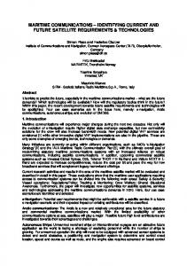
Case b: PEP and cross-layering for ST servers (return path). Suitable PEP functionalities are here considered at the NCC/Gateway to support the TCP flows. In particular, we envisage that the NCC at layer 2 could use an upward cross-layer signaling to notify its transport layer when the capacity available in the satellite network is close to be saturated. The transport layer of the NCC could thus signal to its peer on the ST side that there is congestion (in-band downward signaling exploiting modified TCP acknowledgments, ACK*) so that the increase in traffic injection by TCP could be temporarily stopped. In this direction, the PEP should act as a spoofer on the ACK flow coming from the Internet and modify the ACK to ACK* when there is resource congestion on the satellite side (considering both the capacity that can be allocated to a given ST and its buffer congestion status (threshold method) transmitted at the NCC). The operations at layer 2 to support this PEP are described in Figure 7. This crosslayer approach could prevent the occurrence of massive buffer overflows and consequent TCP repeated timeouts, thus permitting to increase the bandwidth utilization in satellite networks. Such advantages could not be reached with a classical PEP approach. For more details about this scheme the interested reader may refer to [11],[12],[13].
Layer a Write primitive involving non-adjacent layers X-SAP
Layer b SAP
Get primitive
Generic layer
controlling cross-layering
Get primitive
SAP
Write primitive
Layer d Figure 5 Cross-layer exchange of signaling in the horizontal approach.
In this work we consider that cross-layer functions according to the general scheme in Figure 5 can be employed at both the ST and the PEP/Gateway in order to improve the performance of the satellite network. Let us refer to STs using a Demand-Assignment Multiple Access (DAMA) scheme in a GEO bent-pipe satellite network where the Network Control Centre (NCC) is responsible to allocate transmission resources to STs depending on their capacity requests. Moreover, let us refer to a configuration with the NCC co-located with the satellite network gateway towards the Internet (see Figure 6). Crosslayer interactions between layer 2 resource allocation and transport layer could be used to improve TCP performance in broadband satellite networks. This signaling going through SI-SAP would need an X-SAP to allow the direct exchange of information back and forth between layer 2 and layer 4 (non-adjacent layers). In doing so, a new X-SAP interface and related primitives should be considered. The interest is here that BSM may support this signaling and that SI-SAP may be involved in it, since SI-SAP provides a representation of layer 2 status to upper layers. Let us assume that TCP traffic flow is mapped on a suitable layer 3 IP buffer (in the ST if sender, in the PEP Gateway if the sender is in the Internet) that in turn corresponds to a QID at SI-SAP level with related layer 2 queue. Return path
ST
GEO
NCC and gateway
Network
Forward path
Figure 6 Envisaged network architecture with NCC co-located with the Gateway with PEP functions.
In the following study we consider two possible directions of the TCP flow in the satellite network and the related role of the PEP/Gateway/NCC in managing ACKs to control the flow in a situation where the satellite network experiences losses and variable channel conditions (e.g., weather conditions, mobile STs, etc.). We refer to the DVBRCS+M standard [10] with MF-TDMA air interface.
Signaling towards transport layer triggered by MAC layer to notify the PEP about the presence of congestion and the need to stop the ST cwnd increase to
X-SAP
Can DAMA allocate this rate in the next Yes, cwnd could be superframe? allocatated for the next
ST rate value sent in the capacity request together with cwnd
cwnd*
super-frame
?
ST MAC layer signaling (enhanced DAMA capacity request)
DAMA
TBTP MAC layer signaling Yes, yes
Not. A maximum allocable capacity is identified that corresponds to some cwnd* that is lower than
cwnd
?
Is the ST buffer close to congestion ? and cwnd* has been set ?
ST buffer congestion indication
DAMA controller at NCC, MAC layer
Figure 7 Details of the envisaged DAMA controller at the NCC/Gateway with cross-layer exchange of signalling (X-SAP) to support PEP functions.
On the basis of the cross-layer potentialities described above and the characteristics of the cross-layer PEP, the following recommendations and impacts are considered for the BSM protocol structure and SI-SAP interface definition. •
QIDSPEC at SI-SAP could be enriched with cross-layer information (i.e., TCP state coming from upper layer, and PHY modulation -downward direction- and coding conditions coming from physical layer -upward direction).
•
X-SAP interfaces should be defined to support new primitives and the direct exchange of signalling among non-adjacent layers based on the ICMP approach. V. CONCLUSIONS
The ETSI BSM standardisation work is focused on the efficient transport of IP data streams and on how to interoperate resulting satellite networks with terrestrial IP networks. This paper presented the current work in ETSI BSM group in defining the PEP architecture for BSM networks. The ST and Gateway PEP protocol stack has been shown together with distributed and integrated PEP usage scenarios. In addition, this paper analyses the cross-layer improvements. We have studied a type of PEP that operates on the TCP traffic sent by STs through an NCC/Gateway that acts as a PEP-spoofer on ACKs going in the opposite direction. Our main interest is on the adopted cross-layer signaling and related information exchange among layers. Our integrated PEP proposal is non-transparent and requires the application of new cross-layer signaling at the PEP/NCC/Gateway. ACKNOWLEDGMENTS This work was sponsored by the European Telecommunications Standards Institute (ETSI) [14] and supported by the EU Information Society Technologies SatNEx II Network of Excellence [15]. REFERENCES [1] [2] [3] [4] [5] [6]
[7] [8] [9]
IETF document: www.ietf.org. RFC 3135: "Performance Enhancing Proxies Intended to Mitigate Link-Related Degradations". http://www.xiplink.com/IMG/pdf/XipLink_Internet_over_Satellite_O ptimization-R2.pdf http://www.spacebel.be/FR/Space/FastSatDataSheet.pdf http://www.direcway.com/HUGHES/Doc/0/SIKPBJS69O6KP42VCE 4K4ER2BF/Hughes%20PEP_H35661_A4_LR_091206.pdf ETSI TS 102 292, “Broadband Satellite Multimedia (BSM); Functional Architecture”. C. Caini, et al, “ PEPsal: A Performance Enhancing Proxy for TCP Satellite Connections”. IEEE A&E SYSTEMS MAGAZINE, Aug. 2007 I-PEP specifications, Issue 1a. Satlabs group recommendations (http://www.satlabs.org). October 2005. ETSI TS 102 463: "Broadband Satellite Multimedia (BSM); Interworking with IntServ QoS". ETSI TS 102 464: "Broadband Satellite Multimedia (BSM); Interworking with DiffServ QoS".
[10] ETSI. Digital Video Broadcasting (DVB); DVB specification for data broadcasting. ETSI EN 301 790 V1.4.1 (2005-04). Interaction channel for satellite distribution systems", 2005-04. [11] G. Giambene, S. Kota, “Cross-layer Protocol Optimization for Satellite Communications Networks: A Survey”, Int. Journal Sat. Communications and Networking, Vol. 24, pp. 323-341, SeptemberOctober 2006. [12] G. Giambene, S. Hadzic, “A Cross-Layer PEP for DVB-RCS Networks”, in Proc. of the First International Conference on Personal Satellite Services 2009 (PSATS2009), March 18-19, 2009, Rome, Italy. [13] P. Chini, G. Giambene, D. Bartolini, M. Luglio, C. Roseti, “Dynamic Resource Allocation based on a TCP-MAC Cross-Layer Approach for DVB-RCS Satellite Networks”, Int. Journal Sat. Communications and Networking, Vol. 24, pp. 367-385, September-October 2006. [14] ETSI home page: http://portal.etsi.org/Portal_Common/home.asp [15] Satnex project home page: http://www.satnex.de .